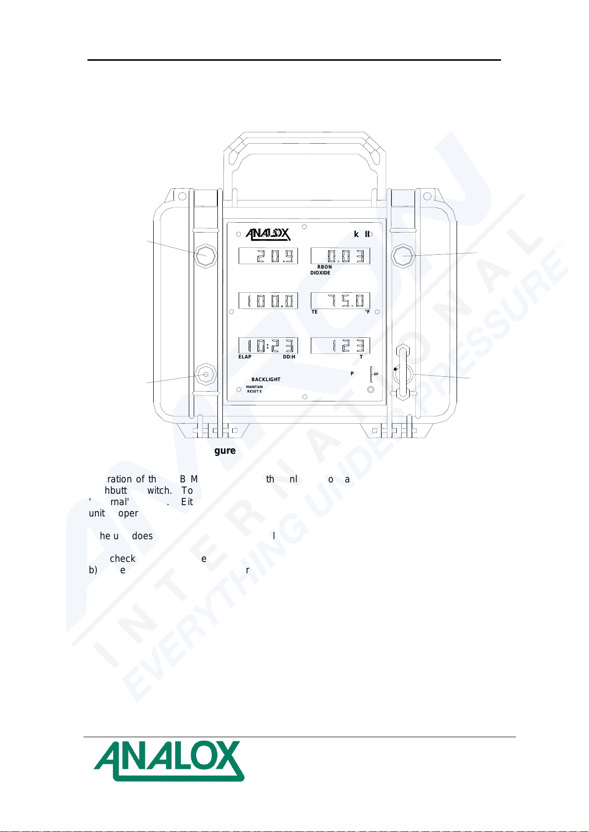
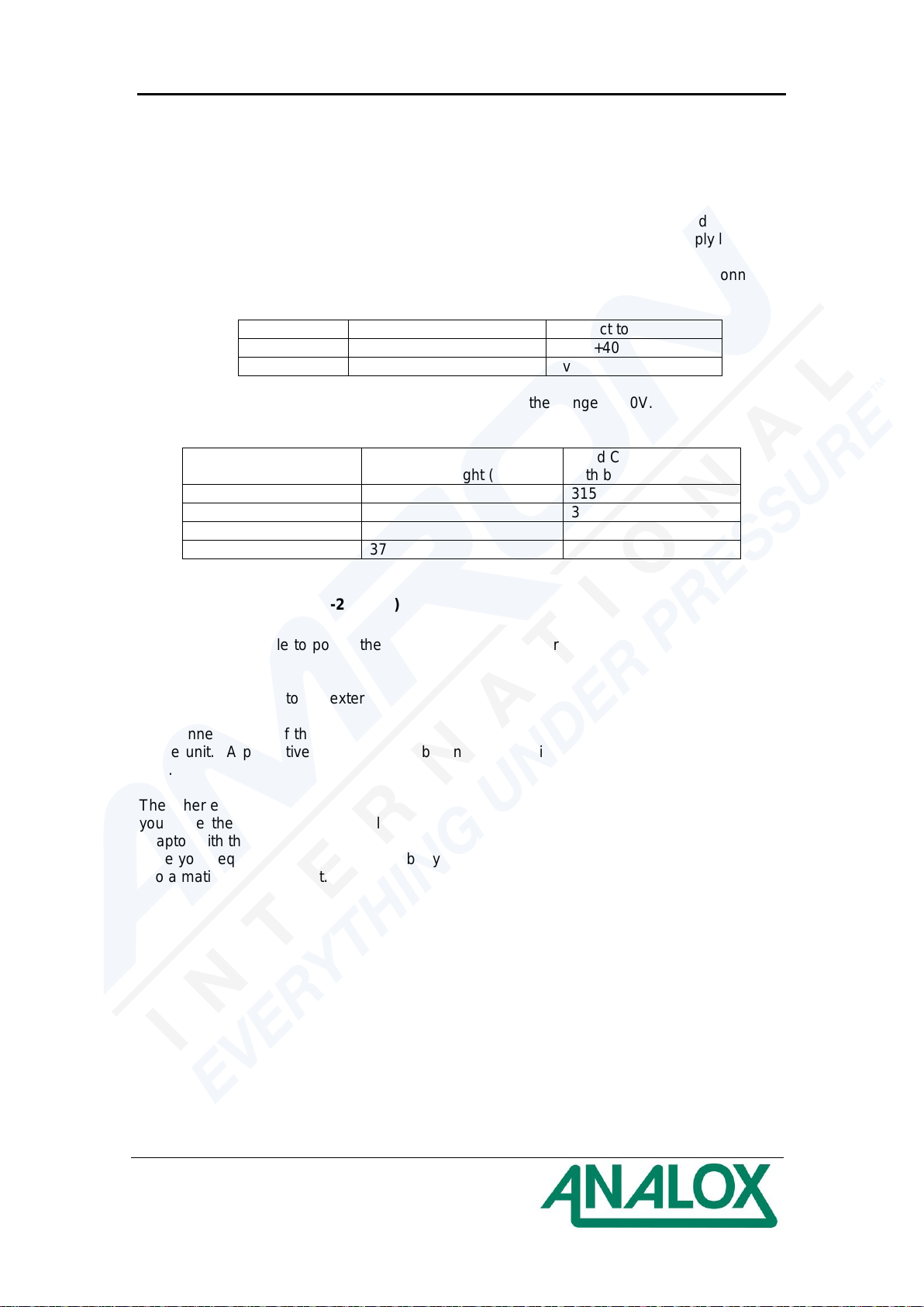
Sub MkIIP Oxygen & Carbon Dioxide Monitor
User Manual - US Navy Version
Document Ref: AS2-802-14 - January 2016
Page 7
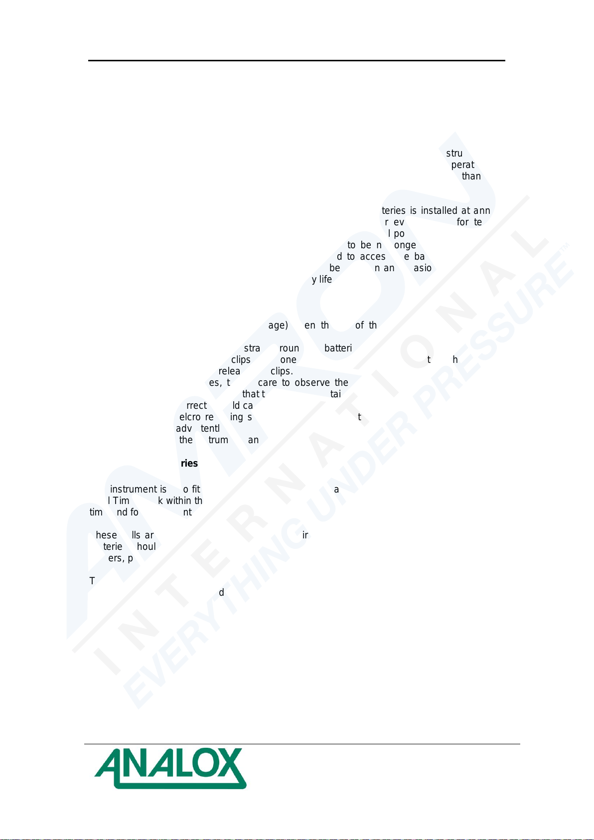
4 Installing batteries
4.1 Main batteries
The instrument is fitted with four 'D' size 1.5v alkaline cells. Although the instrument will
operate from other types of D size battery, their use is not recommended. The operating life
using batteries such as zinc chloride or nickel cadmium will be significantly less than with
alkaline. Batteries with cell voltages in excess of 1.5v must not be fitted.
The instrument is designed such that if a new set of alkaline batteries is installed at annual
maintenance, and if the equipment is then powered for 1 hour every month for testing
purposes, then in the event of a DISSUB incident, the batteries will power the instrument for
in excess of ten days. A DISSUB incident is believed to be no longer than seven days,
therefore under these conditions there will be no need to access the batteries during the
incident. It is assumed that the backlight would only be used on an occasional basis during
this period, since it has the biggest effect on battery life.
To replace the batteries:
a) In dry conditions (to prevent damage) open the lid of the instrument using the two
catches beside the handle
b) Undo the two Velcro retaining straps around the batteries
c) Ease each battery from its clips - use one hand to grip the battery and the other hand to
apply a little pressure to release the clips.
d) Insert the new batteries, taking care to observe the polarity markings on each of the
battery holders, and ensuring that the battery is retained by the clips in the holder. Fitting
the batteries incorrectly could cause them to leak.
e) Refasten the Velcro retaining straps to prevent the batteries becoming dislodged from
their holders inadvertently.
f) Close the lid of the instrument, and secure in place with the two catches.
4.2 Backup batteries
The instrument is also fitted with 2 additional LR43 Alkaline Manganese cells to maintain the
Real Time Clock within the instrument. The Real Time Clock is used to calculate the elapsed
time and for instruments with the data logging option.
These cells are mounted on the main printed circuit board on the underside of the lid. The
batteries should be replaced at 5 year intervals. Observe the polarity markings on the cell
holders, positive uppermost.
The instrument will operate without these batteries fitted, although the Elapsed Time function
will not operate when switched off. Data logging functions (where fitted) will also be affected.