Anilam 4200T User manual

www.anilam.com
4200T
CNC Motion Setup/Testing
Utility


CNC Motion Setup/Testing Utility
P/N 70000634C - Contents
All rights reserved. Subject to change without notice. iii
November 2009
Introduction ...................................................................................................................1
Accessing the MST Utility ............................................................................................1
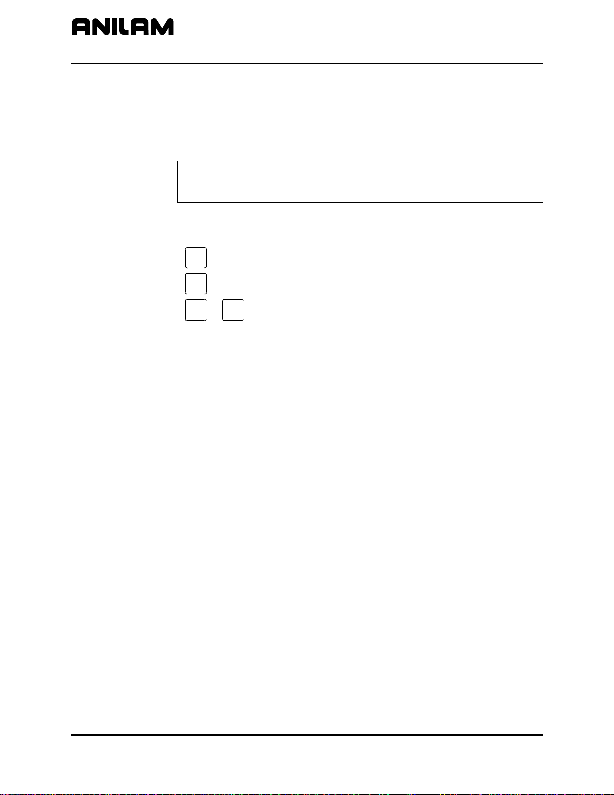
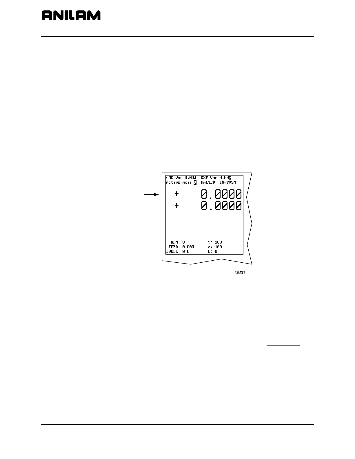
Activating the MST Screen...........................................................................................2
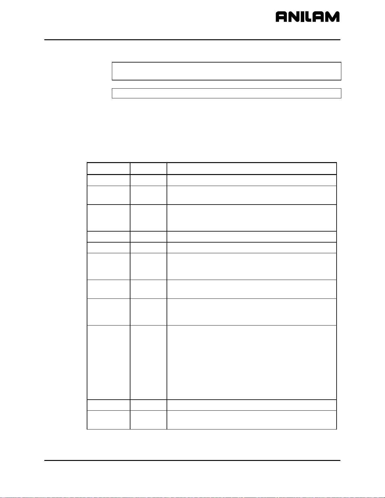
MST Soft Keys...............................................................................................................3
Clearing a Prompt Field or Message (F1) ...........................................................................................4
Selecting an Axis.................................................................................................................................4
Entering a Password...........................................................................................................................4
Checking Axis Resolution (F2)............................................................................................................5
Detecting the Index Pulse (F3)............................................................................................................6
Canceling the Active MDI or Test Command ......................................................................................6
Activating Manual Data Input Mode (MDI)...........................................................................................6
Balancing Motion Control Axes...........................................................................................................7
Differential (AC Systems) and Single-Ended (DC Systems) DSP2 Board ...........................................8
DC Systems........................................................................................................................................9
Servo Drive Test Board...................................................................................................................9
Balancing the DSP2 Board (F6) .....................................................................................................10
Balancing Servo Amplifier Outputs (F6) ........................................................................................12
Amplifier Faults..............................................................................................................................13
Setting the Signal Gain (F7) ..........................................................................................................17
AC Systems ......................................................................................................................................19
Servo Amplifier Test Board............................................................................................................19
Balancing the DSP2 Board (F6) .....................................................................................................21
ANILAM Amplifier Parameter Files................................................................................................22
Balancing Servo Amplifier Outputs (F6) ........................................................................................23
Amplifier Faults..............................................................................................................................27
Miscellaneous Tests (F9) ..............................................................................................................27
AC and DC Systems.........................................................................................................................32
Tuning (F8)....................................................................................................................................32
Saving Final Values.......................................................................................................................35
Exiting the MST Screen (F10) .......................................................................................................35
Setting Up and Tuning the C-Axis .............................................................................36
Index......................................................................................................................................Index-1


CNC Motion Setup/Testing Utility
P/N 70000634C
All rights reserved. Subject to change without notice.
November 2009 1
Introduction This section describes how to use the ANILAM Motion Setup/Testing
(MST) Utility. The MST provides commands that carry out motion-specific
setup and testing in order to tune the servo system and the Proportional,
Integral, and Derivative (PID) filter parameters of a CNC.
A basic knowledge of machine operation and programming is required.
Refer to the 4200T CNC Programming and Operations Manual,
P/N 70000412, for details on how to program and operate the control.
Setup includes the following procedures:
•Servo Amplifier Balancing
•Servo Amplifier Signal Gain Setting (motor step response is displayed
in open loop)
If using amplifiers not provided by ANILAM, follow the manufacturer's
guidelines for balancing, signal gain setting, and overall adjustments.
The CNC provides the following troubleshooting tools:
•Detection of Index Pulse
•Detection of counts between index pulses (actual resolution)
•Tuning for the optimal PID values
The following General Status information is displayed:
•Display of active CNC status codes
•Display of machine position, feedrates, RPM, dwell, and override
Accessing the MST Utility
Access the Motion Setup/Testing Utility (MST) from the Software Options
Screen. This screen activates automatically once the CNC has started
successfully.
To activate the MST Utility:
1. Start the CNC.
2. Press (F10) to continue, as prompted. The Software Options screen
is displayed.
3. Highlight Motion Setup/Testing, and press ENTER. The MST screen
activates.

CNC Motion Setup/Testing Utility
P/N 70000634C
Activating the MST Screen
The axis positions displayed in Figure 1 correspond to the current
position. The Graphic Area displays step responses for the Signal Gain
and Tuning functions. Refer to Figure 1 and Table 1.
General Status
Graphics Area
Active Status Codes
Prompt Area
Message Area
Soft Keys
4MSTSCRN
Figure 1, CNC Motion Setup/Testing Screen
Table 1, MST Screen Areas
MST Screen Area Description
General Status Shows Active Modes, Machine Position for each axis,
RPM, Dwell, Spindle Speed and Feedrate, Active Axis,
and other information regarding the status of the CNC.
Graphic Area Displays step responses for the Signal Gain and Tuning
functions.
Prompt Area Displays messages regarding information that must be
entered.
Active Status Codes Active G-codes.
Message Area Displays error messages.
Soft Keys Function keys (F1–F10) located below the LCD on the
console used to activate the functions, as labeled.
All rights reserved. Subject to change without notice.
November 2009
2

CNC Motion Setup/Testing Utility
P/N 70000634C
All rights reserved. Subject to change without notice.
November 2009 3
MST Soft Keys
NOTE: Select an active axis before you select an MST command
(F1–F10).
NOTE: MST soft keys are displayed while the MST screen is active.
Access MST utility features using the labeled soft keys located below the
screen on the console. Press the corresponding soft key (F1–F10) to
activate the function.
Refer to Table 2 for soft key names and functions.
Table 2, MST Soft Key Functions
Soft Key Name Function
F1 ClrFld
Clears prompt field in SigGain and Tuning tests.
F2 ResChk Calculates the resolution of the active axis.
Troubleshooting tool.
F3 IndexP
Detects Index Pulse and displays an indicator over
the Active Axis line of the MST screen.
Troubleshooting tool.
F4 Manual Cancels active MDI or test command.
F5 MDI Activates an MDI prompt.
F6 Balance Sends out the signal needed to Balance the outputs
of the system (0.0 VDC). Used to balance the
Motion Control Board and the Servo Amplifiers.
F7 SigGain Allows you to set the servo amplifier signal gain for
the active axis.
F8 Tuning Activates the Tuning Pop-Up menu, which allows the
CNC to determine optimum PID filter values from the
specified parameters and save the results.
F9 Misc Miscellaneous tests displays a pop-up menu with
options for CanBus Test. For AC motors only
additional options display on the pop-up menu:
Amplifier Test Link, Reset Amplifier, Backup Amp
Settings, and Restore from Backup. These tests can
only be activated with the Servo Amplifier Test Board
installed. See for DC systems “Servo Drive Test
Board” or for AC systems “Servo Amplifier Test
Board.”
F10 Exit Returns the CNC to the Software Options screen.
(SHIFT+F4) Home Performs a Homing Sequence on all axes configured
for homing.

CNC Motion Setup/Testing Utility
P/N 70000634C
Clearing a Prompt Field or Message (F1)
Press ClrFld (F1) to clear an erroneous entry. This soft key is available
during the Signal Gain and Tuning tests.
Selecting an Axis
NOTE: Select an active axis before you select an MST command
(F1–F10). If you do not select an axis, the CNC displays an
Error message that prompts you to select an axis.
Use the following keypad keys to select and activate the corresponding
axes:
XActivates/Deactivates X-axis
ZActivates/Deactivates Z-axis
Sor SActivates/Deactivates Spindle Axis
X
Z
S C
The CNC displays the active axis in the upper-left corner of the General
Status area of the MST Screen.
Entering a Password
When you enter the MST Utility and press Balance (F6), SigGain (F7), or
Tuning (F8), the CNC prompts for the password. Type the appropriate
password and press ENTER. Refer to 4200T CNC Setup Utility Manual,
P/N 70000414, “Section 1, Password Restricted Parameters.”
The soft key activates. If you have entered the password successfully,
the CNC will not prompt for the password again, unless you exit and
re-enter the MST Utility.
All rights reserved. Subject to change without notice.
November 2009
4

CNC Motion Setup/Testing Utility
P/N 70000634C
Checking Axis Resolution (F2)
Refer to Figure 2. Press ResChk (F2) to calculate the actual resolution
for the active axis. In the Graphic Area of the screen, the actual
resolution and the resolution in the Setup are displayed for comparison.
In addition, the screen displays:
•The number of times the system tested for resolution (Total Cycles:)
•The number of times the encoder lines detected do not match the
number of encoder lines in the setup (Errors:). An error indicates that
something is wrong, either in the setup parameters or in the hardware.
•The actual number of encoder lines found by the test (Encoder Lines:)
•The resolution and counts per revolution found. (Encoder
Resolution:)
NOTE: Resolution should be four times the number of encoder lines.
Once this test is activated, you must move the axis for at least two
encoder revolutions via MDI Mode, Jog Mode, or manual move. The
CNC performs the calculation continuously until motion stops.
NOTE: This test is not available for axes with linear encoders.
NOTE: Do not perform this test during Rapid Mode. Use it in Feed
Mode only.
4RESCHK
Figure 2, CNC Resolution Check (ResCheck) Screen
All rights reserved. Subject to change without notice.
November 2009 5

CNC Motion Setup/Testing Utility
P/N 70000634C
Detecting the Index Pulse (F3)
Refer to Figure 1, CNC Motion Setup/Testing Screen. When you press
IndexP (F3), the CNC displays a flashing “I” each time it detects an Index
Pulse. The flashing “I” replaces the axis name (X, Z, or S) of the active
axis. The index pulse indicator (flashing “I”) for the spindle axis is
displayed on the RPM field. The figure shows the axis display when the
CNC has detected an index pulse in the (active) X-axis. Refer to
Figure 3.
To detect an index pulse:
1. Move the active axis to check for the presence of an index pulse.
2. On systems with rotary encoders with index pulses, the index pulse
should be detected once per revolution.
3. On systems having linear scales, the index pulse should be detected
where the linear scale specifies location of the index pulse.
Index Pulse
Indicato
r
I
Z
Figure 3, Index Pulse Indicator
Canceling the Active MDI or Test Command
Press Manual (F4) to cancel an active MDI or test command.
Activating Manual Data Input Mode (MDI)
Press MDI (F5) to activate the MDI prompt. (Refer to the 4200T CNC
Programming and Operations Manual, P/N 70000412, for information on
MDI programming.)
All rights reserved. Subject to change without notice.
November 2009
6

CNC Motion Setup/Testing Utility
P/N 70000634C
All rights reserved. Subject to change without notice.
November 2009 7
Balancing Motion Control Axes
To balance the outputs properly, all connections between the CNC and
the servo amplifiers must be complete.
Perform all adjustments on one axis at a time. Make the adjustments in
the following order:
1. Select an axis
2. Balance the Motion Control Board outputs
3. Balance the Servo Amplifier outputs
4. Set Servo Amplifier gain
5. Repeat for all axes

CNC Motion Setup/Testing Utility
P/N 70000634C
Differential (AC Systems) and Single-Ended (DC Systems) DSP2 Board
The digital signal processing (DSP)2board uses digital input and provides
analog output. For the AC systems, the DSP2board, P/N 33001102, is
differential (see Figure 4). The earliest AC systems were single-ended
DSP2boards. For DC systems, the DSP2board, P/N 33001102, is single-
ended (see Figure 5).
NOTE: In the illustrations, see the difference in the jumper pin direction
for pins: J10–J17.
Figure 4, Differential DSP2Board, P/N 33001102, AC Systems
Figure 5, Single-Ended DSP2Board, P/N 33001102, DC Systems and earliest AC Systems
All rights reserved. Subject to change without notice.
November 2009
8

CNC Motion Setup/Testing Utility
P/N 70000634C
DC Systems
There are a number of differences for DC system and AC systems. The
features specific to the DC systems are described in this section.
Servo Drive Test Board
Each CNC that uses ANILAM servo amplifiers (P/Ns 33000039 or
33000123) includes a Servo Drive Test Board, P/N 33000102. During
machine operation, the board provides convenient access to critical
signals for alignment and troubleshooting. Refer to Figure 6.
description
NOTE: The test board works only with amplifiers supplied by ANILAM.
Figure 6, ANILAM DC System Servo Drive Test Board, P/N 33000102, DC Systems
Test-Board Installation
IMPORTANT: Press E-STOP to de-energize servos before you install the
test board.
1. Remove the cable attached to J1 of the Servo Drive you wish to
monitor and connect it to P1 of the test board. installation
2. Attach W1 of the test board to J1 of the servo.
3. Re-energize the servos.
All rights reserved. Subject to change without notice.
November 2009 9

CNC Motion Setup/Testing Utility
P/N 70000634C
All rights reserved. Subject to change without notice.
November 2009
10
Test Points
Refer to Table 3 for a description of test points and signals.
Table 3, Servo Drive Test Board: Test Points and Signals
Test Point Pin Signal
TP1 3
Command Signal
TP2 4
Common for all servo signals and potentiometers.
All readings are referenced to TP2.
TP3 5
Tachometer
TP4 6
Motor Current output monitor. The scale factor is 1V
= 5A.
TP5 9
Clamp input from the SCB. When pulled to chassis
ground, the servo’s output is forced to 0 VDC.
TP6 10
Fault Output. When the servo card is faulted, the
output is pulled low. If TP6 is pulled to chassis
ground, the Servo is disabled and coasts to a stop.
JMP1 11
Command Signal Common. If removed, JMP1 will
open the common line at Pin 11 of J1.
JMP2 3
Common Signal. If JMP2 is removed, the Command
signal will open at Pin 3 of J1.
Jumpers
While troubleshooting, you can remove jumpers to isolate the Servo Drive
from the DAC outputs of the Motion Control Board. If you short Pin 2 of
JMP1 and JMP2 together, the Servo Drive’s input is fixed at 0 VDC; this
can be useful while troubleshooting balance problems.
Balancing the DSP2 Board (F6)
On systems that use an ANILAM Servo Amplifier Board, P/N 33000039 or
33000123 (See Figure 8 (5 LEDS), DC Systems or Figure 9 (1 LED),
DC Systems), you can make measurements for this procedure at the J1
input connector with the Servo Drive Test Board, P/N 33000102.
NOTE: If ANILAM did not provide the servo amplifiers, follow the
guidelines for balancing supplied by the manufacturer.
Refer to Figure 7, ANILAM DSP2Board Balance Pots, P/N 33000404,
DC Systems. Measure command voltages across TP1 and TP2 of the
test board.
NOTE: You can find these signals on Pin 3 and Pin 11 of the J1 input
connector on the ANILAM Servo Amplifier Board.
All DSP2Boards are adjusted at the factory and should be within limits.
Balance the DSP2Board only if it is not at 0 VDC (±0.001V).

CNC Motion Setup/Testing Utility
P/N 70000634C
NOTE: On 4200T systems, the DSP2 Boardis located in the CNC
chassis. Open the CNC chassis by loosening the thumbscrews
and opening the cover. Balance the DSP2Board with the servos
off, initially. Next, verify the DSP2Board balance with the servos
on, and correct for voltage offset as required.
1. Press Balance (F6) to output a zero-voltage signal to the axis.
2. Press START.
3. Refer to Figure 7. Make adjustments for axis outputs 0-3 on the
DSP2Board at potentiometers R108-R111 respectively.
4. Adjust the potentiometer for the selected axis until the voltage across
the pins is 0VDC (±0.001V).
5. Press Manual (F4) to cancel the test.
Table 4, Axis Output Port Assignments
Port Axis
0 X
1 C/S
2 Z
33000404
Output Balance Pot
Port 0
Port 1
Port 2
Port 3
Figure 7, ANILAM DSP2Board Balance Pots, P/N 33000404, DC Systems
All rights reserved. Subject to change without notice.
November 2009 11

CNC Motion Setup/Testing Utility
P/N 70000634C
Balancing Servo Amplifier Outputs (F6)
When the command signal voltage from the DSP2Board is 0, the axis
should be stationary and MST balance display should read “0000”.
Alternatively, read the tachometer voltage from the motor. The
tachometer should read 0 VDC (±0.001 V). Monitor the tachometer
voltage across TP2 and TP3 of the test board.
NOTE: You can find these signals also on Pins 5 and 11 of the J1 input
connector on the ANILAM Servo Amplifier Board, P/N
33000123. Refer to Figure 8, (5 LEDs), DC Systems or
Figure 9, ANILAM Servo Amplifier (1 LED), P/N 33000123,
DC Systems.
CUR MODE
VELMODE
INTEGRATOR
LIMIT H/L
INHIBIT H/L
RESET H/L
LIMITU/D
INHIBIT U/D
RESET U/D
+15/+5
S1
DIFF SIG + 1
DIFF SIG - 2
SIGNAL IN 3
COMMON 4
TACH 5
MTR CUR 6
LIMIT + 7
LIMIT - 8
CLAMP 9
FAULT 10
COMMON 11
RESET 12
LS/ECB 13
HS/ECB 14
OVERVOLT 15
OVERTEMP 16
LOOP GAIN POT
RESET SWITCH
J1
COMMON
SIGNAL
TACH
DIFF SIG GAIN
SIG GAIN
TACH GAIN
COMP
RUN
OVER TEMP
OVER VOLT
LS/ECB
HS/ECB
J2 LEDS
TEST POINTS
DIFF GAIN
SIG GAIN
BAL
TACH
COMP
IR COMP
FLDBK
I LIMIT
POTS
BUS RET 1
B + 2
MOTOR - 3
MOTOR + 4
TB1
SMA7215-1
BRUSHTYPE AMPLIFIER
CAUTION
HIGH VOLTAGE!
SERVO2
Figure 8, ANILAM Servo Amplifier (5 LEDS), P/N 33000123, DC Systems
NOTE: When the amplifier is shipped from the factory, the LOOP GAIN
pot is fully counterclockwise (CCW). This is used to shut off
uncalibrated amplifiers. When the loop gain is fully CCW, no
current is delivered to the motor.
1. Apply main power and fan power.
2. Slowly turn the LOOP GAIN pot clockwise (CW). Motor should be
stopped or turning slowly. If motor starts running away, remove
power, reverse the tach leads, and retest. Turn the LOOP GAIN fully
CW to enable.
3. Energize the servos and select an axis.
4. Refer to Figure 10, Balance Screen, DC Systems. Press Balance
(F6) to output a zero voltage signal to the axis.
5. Press
START.
All rights reserved. Subject to change without notice.
November 2009
12

CNC Motion Setup/Testing Utility
P/N 70000634C
6. On the ANILAM Servo Amplifier for the axis being adjusted, adjust the
balance potentiometer until the MST display indicates 0000, indicating
the active axis is stationary.
– or –
Adjust until tach voltage is 0 VDC (±0.001 V), indicating that the active
axis is stationary.
7. Press MANUAL (F4) to cancel the Balance command.
AMP
-
1LED
COMP
DIFF SIG GAIN
TEST POINTS
J2
TACH GAIN
DIFF GAIN
SIG
COM
SIG GAIN
TACH
POTS
SMA7215-1
BRUSHTYPE AMPLIFIER
OVERTEMP
COMMON
RESET
BUS RET
LIMIT
LIMIT
HS/ECB
LS/ECB
RESET
COMMON
FAULT
DIFF SIG
DIFF SIG
MTR CUR
TACH
SIGNAL IN
INHIBIT
OVERVOLT
J1
12
13
4
+2
1
3
8
9
6
5
7
+
10
11
16
14
15
1
B
MOTOR
MOTOR
HIGH VOLTAGE
CAUTION
TB1
+2
3
+4
SIG GAIN
BAL
TACH
COMP
CUR LIMIT
LOOP GAIN
LED INDICATORS
GREEN RED CONDITION
OFFON RUN
2 FLASHESON +/- LIMITS
OFFOFF AMPLIFIER INHIBIT
ONOFF RESET
1 FLASHOFF OVERTEMP
2 FLASHESOFF OVERVOLTAGE
3 FLASHESOFF LS/ECB
4 FLASHESOFF HS/ECB
Figure 9, ANILAM Servo Amplifier (1 LED), P/N 33000123, DC Systems
Amplifier Faults
ANILAM amplifiers do not require any scheduled maintenance, although it
is a good idea to occasionally check for dust build up or other
contamination.
If an amplifier should cease to operate or one or more of the fault LEDs
are lit, review the following sections for information on the fault and
possible causes.
NOTE: A fault can on be caused by abnormal conditions. Locate and
correct the cause of the fault before repeated recycling of power
to the amplifier to prevent possible damage.
For LED fault conditions on 5 LED servo amplifiers (Figure 8, ANILAM
Servo Amplifier (5 LEDS), P/N 33000123, DC Systems), see Table 5,
Table of Fault LED Conditions (5 LEDs).
All rights reserved. Subject to change without notice.
November 2009 13

CNC Motion Setup/Testing Utility
P/N 70000634C
All rights reserved. Subject to change without notice.
November 2009
14
Table 5, Table of Fault LED Conditions (5 LEDs)
Input or Fault
Condition RUN
LED HS/ECB
LED LS/ECB
LED OVER VOLT
LED OVER TEMP
LED FAULT
OUTPUT
NORMAL
OPERATION ON OFF OFF OFF OFF GROUND
LIMIT + (ON) ON OFF OFF OFF OFF GROUND
LIMIT – (ON) ON OFF OFF OFF OFF GROUND
CLAMP (ON) OFF OFF OFF OFF OFF GROUND
RESET (ON) OFF OFF OFF OFF OFF PULL-UP
EXT. FAULT OFF OFF OFF OFF OFF PULL-UP
UNDER VOLTAGE
(+15V) OFF OFF OFF OFF OFF PULL-UP
HS/ECB (LATCHED) OFF ON OFF OFF OFF
PULL-UP
LS/ECB (LATCHED) OFF OFF ON OFF OFF
PULL-UP
OVER VOLTAGE B+
(LATCHED) OFF OFF OFF ON OFF PULL-UP
OVER TEMP
(LATCHED) OFF OFF OFF OFF ON PULL-UP
For LED fault conditions 1 LED servo amplifiers, see Figure 9, ANILAM
Servo Amplifier (1 LED), P/N 33000123, DC Systems or Table 6.
Table 6, Table of Fault LED Conditions (1 LED)
Green Red Condition
ON OFF RUN
ON 2 FLASHES +/– LIMITS
OFF OFF AMPLIFIER INHIBIT
OFF ON RESET
OFF 1 FLASH OVER TEMPERATURE
OFF 2 FLASHES OVER VOLTAGE
OFF 3 FLASHES LS/ECB
OFF 4 FLASHES HS/ECB

CNC Motion Setup/Testing Utility
P/N 70000634C
All rights reserved. Subject to change without notice.
November 2009 15
Under Voltage Fault
When the +15VDC power supply is below +12VDC, a level that would
cause unreliable operation: description
For 5 LED amplifiers: The Run LED turns off, a Fault Output is
generated, and the amplifier is inhibited.
For 1 LED amplifiers: The Green LED turns off, the Red LED is off, a
Fault Output is generated, and the amplifier is
inhibited.
The following is a list of possible causes:
•Main buss line voltage is too low
•Bad power supply
High Speed Electronic Circuit Breaker (HS/ECB) Fault
When the peak output of the amplifier exceeds 80A for 10 microseconds:
For 5 LED amplifiers: The Run LED turns off, the HS/ECB LED turns
on, a Fault Output is generated, and the
amplifier is inhibited.
NOTE: This is a latched condition.
For 1 LED amplifiers: The Green LED turns off, the Red LED
displays 4 flashes, a Fault Output is
generated, and the amplifier is inhibited.
NOTE: This is a latched condition.
The following is a list of possible causes:
•Shorted motor leads.
•Motor inductance too low.
•Short from the motor lead to ground.
Low Speed Electronic Circuit Breaker (LS/ECB) Fault
When the RMS output of the amplifier exceeds 13A for 5 seconds:
For 5 LED amplifiers: The Run LED turns off, the LS/ECB LED turns
on, a Fault Output is generated, and the
amplifier is inhibited.
NOTE: This is a latched condition.
For 1 LED amplifiers: The Green LED turns off, the Red LED
displays 3 flashes, a Fault Output is
generated, and the amplifier is inhibited.
NOTE: This is a latched condition.
The following is a list of possible causes:
•Binding or stalling of motor shaft due to excessive mechanical
overload.
•Overload of amplifier output to motor.
•Large reflected load inertia.

CNC Motion Setup/Testing Utility
P/N 70000634C
All rights reserved. Subject to change without notice.
November 2009
16
Over Temp Fault
When the amplifier heatsink temperature has reached a level that, if
exceeded, would damage the output transistors:
For 5 LED amplifiers: The Run LED turns off, the OVER TEMP LED
turns on, a Fault Output is generated, and the
amplifier is inhibited.
NOTE: This is a latched condition.
For 1 LED amplifiers: The Green LED turns off, the Red LED
displays 1 flash, a Fault Output is generated,
and the amplifier is inhibited.
NOTE: This is a latched condition.
The following is a list of possible causes:
•Loss of cooling, or fans are defective, or airflow is blocked.
•Excessive rise in cooling temperature due to cabinet vents being
blocked or excessive hot air being ingested.
•Extended operational duty cycle due to mechanical overload of motor
or defective motor.
Over Voltage Fault
When the DC Buss voltage reaches 250VDC:
For 5 LED amplifiers: The Run LED turns off, the OVER VOLTAGE
LED turns on, a Fault Output is generated, and
the amplifier is inhibited.
NOTE: This is a latched condition.
For 1 LED amplifiers: The Green LED turns off, the Red LED
displays 2 flashes, a Fault Output is
generated, and the amplifier is inhibited.
NOTE: This is a latched condition.
The following is a list of possible causes:
•Main Buss line voltage is too high.
•Decelerating a large inertial load. When decelerating, a DC motor
acts as a generator. If the inertial load is large, the generated voltage
can pump up the DC-Buss. If this fault occurs, you may need a
Regen Clamp. Consult ANILAM.
Resetting a Fault
The fault latch may be reset by pushing the Reset button, activating the
Reset input J1–12 or by removing power and allowing the filter
capacitor(s) to discharge. Note that the fault latch will not reset unless
the fault has been cleared.
Other manuals for 4200T
2
Table of contents