User manual | ANTMIX Series
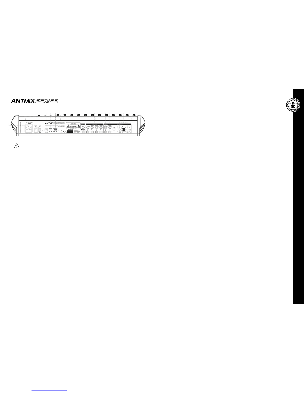
1 MAINS INPUT
Plug into this socket the mains cord supplied with the unit. Make sure the unit is turned OFF before connecting the cable to
the mains. For your safety, never disconnect the earth lead.
2 FUSE
Protection fuse.
WARNING: Replace the fuse only with one of the same type and with the same value.
If the fuse blows repeatedly, contact an authorized service center.
3 POWER ON/OFF
Press this switch to turn ON or OFF the unit.
4 +48V
This switch allows you to turn ON or OFF the phantom power for condenser microphones:
ON = Switch turned ON (depressed to the top), +48V LED lit.
OFF = Switch turned OFF, +48V LED turned off.
5 USB PORT
This type B USB port allows connection to a computer or other audio device with a USB interface.
6 RECORD
This selector allows you to choose the signal to send to the device connected to the USB port. Set it to MAIN MIX when you want
to record the signal assigned to that stereo or to GR 1-2 when you want to record the signal assigned to that stereo group.
7 PLAYBACK
Use this selector to choose the signal you want to hear from the device connected to the USB port. Set this switch to MAIN MIX to
send the audio signal coming from the computer (or from the connected audio device) directly to the MAIN MIX outputs or to CH
15-16 (ANTMIX 16FX USB) / CH 23-24 (ANTMIX 24FX USB) to assign it to the above mentioned channels.
NOTE: if you assign the USB audio signal to channels 15-16 / 23-24, listen to the LINE / USB switch (3) on the front panel and
choose USB.
NOTE: to avoid digital loops when overdubbing, assign the RECORD switch to GR1-2 and the PLAYBACK selector on the stereo
channel 15-16 / CH 23-24 assigning it only to GR3-4 or MAIN MIX.
8 DFX ST OUT
The signal from the internal effects processor is present in this balanced stereo output, 6.35mm jack.
9 FOOTSW.
Connect an external pedal to this unbalanced jack for inserting or excluding internal effects. Press once to deactivate the effects
(DFX MUTE function), press a second time to reactivate them.
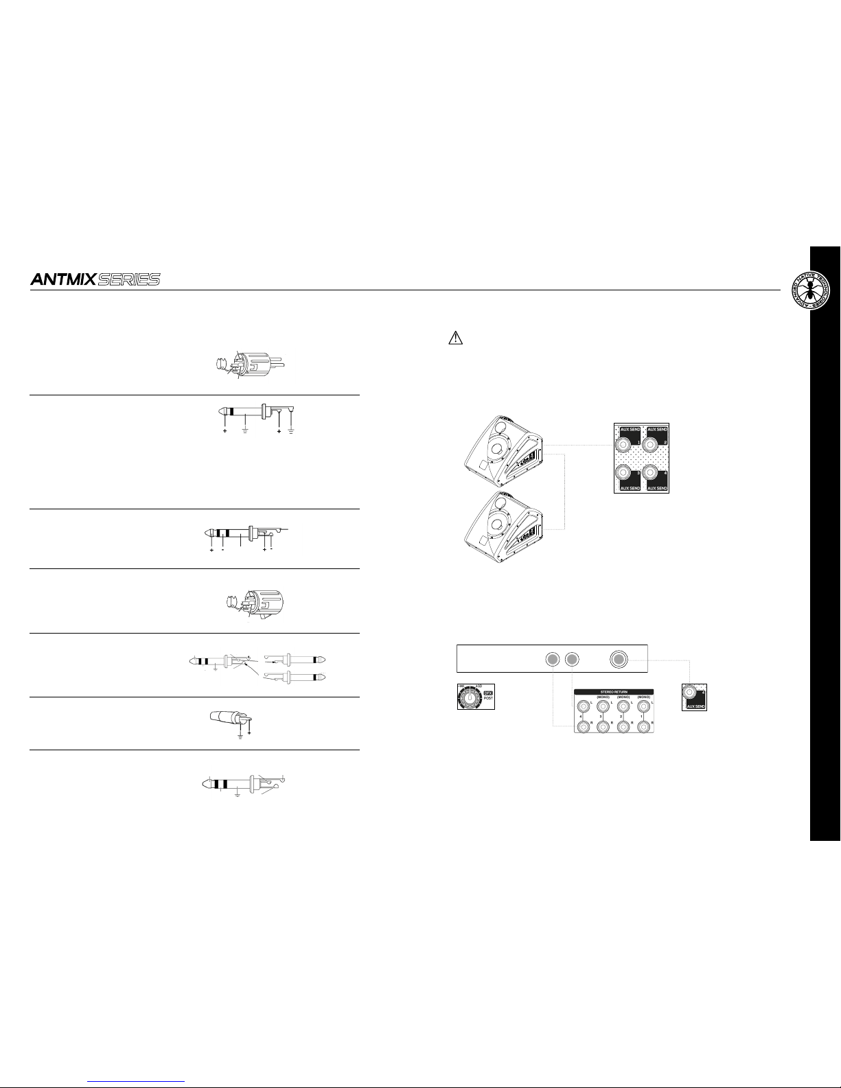
10 STEREO RETURN(S)
Connect to these input jacks the return of an external effects unit or other stereo or mono device. For each STEREO RETURN
auxiliary return (1-2-3-4) there are two audio inputs - L (MONO)/R - on 6.35mm balanced jack connectors
11 MAIN INSERT
6.35mm jack sockets for insertion of external processors (eg EQ or compressors) in the MAIN circuit, the tip of the jack sends the
signal to the processor, the ring receives the processed signal, while the sleeve has the signal of both grounds.
12 MAIN MIX OUT
6,35mm unbalanced jack outputs. Connect the inputs of your amplication system or master recorder to these outputs.
13 +4dBU/-30dBU
This selector allows you to select the output level between +4 dBu and -30 dBu to optimize the connection for any destination.
14 MAIN MIX OUTPUT
Balanced XLR-M outputs. Connect the inputs of your amplication system or master recorder to these outputs.
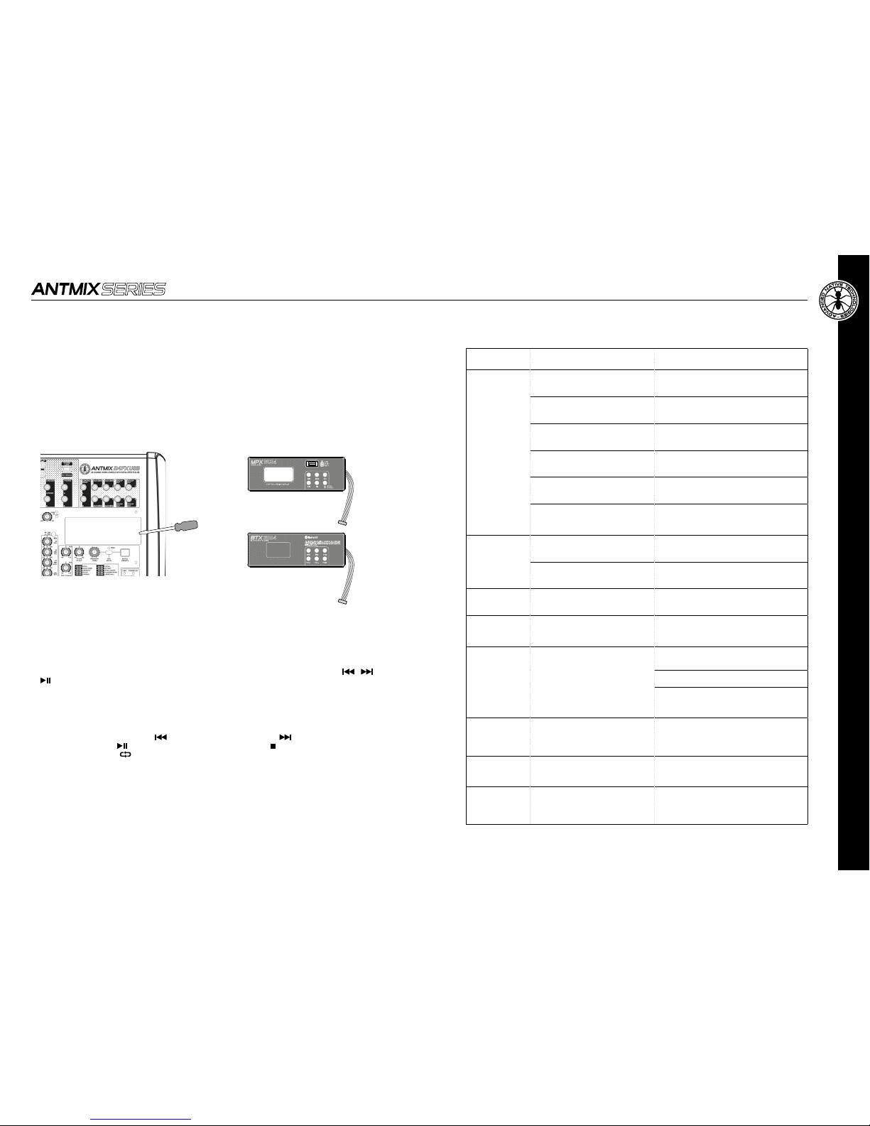
1 RECORD
Select the source for recording between GR1-2 and MAIN MIX.
MAIN MIX is ideal for recording a live session or basic tracks (rhythm or other) while during overdubbing it is advisable
to record from GR1-2 and use MAIN MIX for direct listening
NOTE: to avoid annoying loops, never choose MAIN MIX when playback is on MAIN MIX.
Do not route the GR1-2 signal to MAIN MIX!
2 PLAYBACK
Allows you to select the channels to listen the USB port signal.
During playvack and/or overdubs, it is advisable to listen via CH15-16 (23-24) both to give the right level to each AUX
that equalize. MAIN MIX is ideal for audience listening and for the nal mixing.
NOTE: if you desire to listen to the USB port signal, beside setting this switch to CH15-16 (CH23-24) you have to press
the USB key of the relative stereo channel of the mixer.
APPLICATION
Playback
Set the selector to PLAYBACK on CH15-16 (or CH23-24) and press the USB key of the last stereo channel (15-16 or
23-24) to listen to the playback tracks signals from PC/tablet. In this way you can adjust signals for monitors and
musicians, via AUX1 and 2 independently of the MAIN MIX levels (possibly also AUX 3 but remember that it is post-
fader) and equalize the signal.
Karaoke
Set the selector to PLAYBACK on CH15-16 (or CH23-24) and press the USB key of the last stereo channel (15-16 or
23-24) to listen to the playback tracks signals from PC/tablet. In this way you can adjust signals for monitors and
musicians, via AUX1 and 2 independently of the MAIN MIX levels (possibly also AUX 3 but remember that it is post-
fader) and equalize the signal.
Recording
Set RECORD to MAIN MIX, and assign the channels you want to record to the L-R output and adjust the volumes.
Assign the signals you do not want to record to GR3-4 and adjust the signal for the headphones of the musicians via
the AUX sends.
Overdub
Set the RECORD selector to GR1-2, and assign the channels you want to record to the GR1-2 output and adjust the
volumes.
For listening, put PLAYBACK on CH15-16 or CH23-24 and press the USB key of the last stereo channel (15-16 or 23-24)
to listen to PC/tablet playback tracks. Adjust the signal for the musicians' headphones via the AUX 1, 2 and 3 sends
(there is no risk of feedback in the headphones)
Assignthe signals you donotwant to record to GR3-4andadjust the signal for musiciansheadphonesvia the AUX sends.
Mixing
You can make an ITB mix and listen either through the last stereo channel by setting PLAYBACK on CH15-16 (23-24),
in this way you can do minimal EQ adjustments. Otherwise you can set the PLAYBACK on MAIN MIX to listen with no
action except volume adjustment.
3.1.4 | USB INTERFACE & APPLICATIONS
1
2
3 4 5 6 7 8 10 11 12 14
9 13