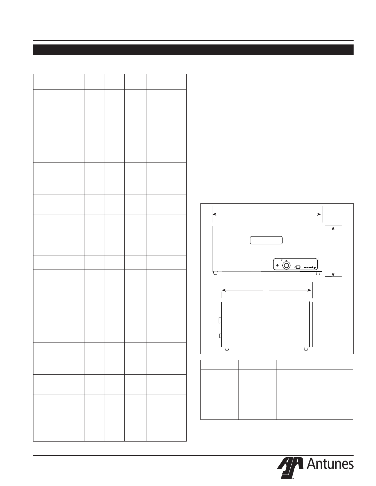
Antunes WD-20 Series User manual

P/N 1010612 Rev.. D 08/17
Warmer Drawer
owner’s manual
Models WD-20, WD-21A, & WD-35
Manufacturing Numbers:
9400100, 9400101, 9400102, 9400103, 9400104,
9400106, 9400110, 9400111, 9400112, 9400113,
9400114, 9400120, 9400121, 9400122, 9400123,
and 9400124,
www.antunes.com

WARMER DRAWER
2P/N 1010612 Rev. D 08/17
General
The Warmer Drawers are designed to be used sepa-
rately, stacked or to fit under the Hot Dog Corrals.
This manual provides the safety, installation and oper-
ating procedures for the Warmer Drawer. We recom-
mend that all information contained in this manual be
read prior to installing and operating the unit.
Your Warmer Drawer is manufactured from the finest
materials available and is assembled to our strict qual-
ity standards. This unit has been tested at the factory
to ensure dependable trouble-free operation.
Warranty Information
Please read the full text of the Limited Warranty in this
manual.
OWNER INFORMATION
TABLE OF CONTENTS
IMPORTANT! Keep these instructions for future reference.
If the unit changes ownership, be sure this manual accompanies the equipment.
If the unit arrives damaged, contact the carrier imme-
diately and file a damage claim with them. Save all
packing materials when filing a claim. Freight damage
claims are the responsibility of the purchaser and are
not covered under warranty.
The warranty does not extend to:
• Damages caused in shipment or damage as
result of improper use.
• Installation of electrical service.
• Normal maintenance as outlined in this manual.
• Malfunction resulting from improper maintenance.
• Damage caused by abuse or careless handling.
• Damage from moisture into electrical
components
• Damage from tampering with, removal of, or
changing any preset control or safety device.
Table of Contents .......................................................2
Owner Information .....................................................2
General......................................................................2
Warranty Information .................................................2
Service/Technical Assistance ....................................3
Important Safety Information ....................................3
Specifications .............................................................5
Electrical Ratings and Plug Configuration.................5
Capacity.....................................................................5
Shipping Weight ........................................................5
Dimensions................................................................5
Installation...................................................................6
Unpacking..................................................................6
Equipment Setup.......................................................6
Operation.....................................................................7
Operating Instructions ...............................................7
Hi-Limit Reset ............................................................7
Maintenance................................................................8
Cleaning ....................................................................8
Replacing Components .............................................8
Troubleshooting .......................................................10
Wiring Diagram.........................................................10
Pictorial Wiring Diagram..........................................10
Replacement Parts - WD-20 .................................... 11
Replacement Parts – WD-21A & 35A......................13
Notes..........................................................................15
Limited Warranty ......................................................16

3
WARMER DRAWER
P/N 1010612 Rev. D 08/17
Throughout this manual, you will find the following safety words and symbols that signify important safety issues with
regards to operating or maintaining the equipment.
WARNING
GENERAL WARNING. Indicates informa-
tion important to the proper operation of
the equipment. Failure to observe may
result in damage to the equipment and/or
severe bodily injury or death.
WARNING
ELECTRICAL WARNING. Indicates infor-
mation relating to possible shock hazard.
Failure to observe may result in damage
to the equipment and/or severe bodily
injury or death.
CAUTION
GENERAL CAUTION. Indicates informa-
tion important to the proper operation of
the equipment. Failure to observe may
result in damage to the equipment.
WARNING
HOT SURFACE WARNING. Indicates
information important to the handling of
equipment and parts. Failure to observe
caution could result in personal injury.
IMPORTANT SAFETY INFORMATION
Service/Technical Assistance
If you experience any problems with the installation
or operation of your unit, contact Antunes Technical
Service at +1-877-392-7854 (toll free).
Fill in the information below and have it handy when
calling Antunes Technical Service for assistance. The
serial number is on the specification plate located on
the side of the unit.
Purchased From:
Date of Purchase:
Model No.:
Serial No.:
Mfg. No.:
OWNER INFORMATION (continued)
Use only genuine Antunes replacement parts in this
unit. Use of replacement parts other than those sup-
plied by the manufacturer will void the warranty.

WARMER DRAWER
4P/N 1010612 Rev. D 08/17
In addition to the warnings and cautions in this manual,
use the following guidelines for safe operation of the
unit.
• Read all instructions before using equipment.
• For your safety, the equipment is furnished with
a properly grounded cord connector. Do not
attempt to defeat the grounded connector.
• Install or locate the equipment only for its intend-
ed use as described in this manual. Do not use
corrosive chemicals in this equipment.
• Do not operate this equipment if it has a dam-
aged cord or plug, if it is not working properly, or
if it has been damaged or dropped.
• This equipment should be serviced by quali-
fied personnel only. Contact Antunes Technical
Service adjustment or repair.
• Do not block or cover any openings on the unit.
• Do not immerse cord or plug in water.
• Keep cord away from heated surfaces.
• Do not allow cord to hang over edge of table or
counter.
The following warnings and cautions appear
throughout this manual and should be carefully
observed.
• Turn the unit off, disconnect the power source
and allow unit to cool down before performing
any service or maintenance on the unit.
• The procedures in this chapter may include
the use of chemical products. These chem-
ical products will be highlighted with bold
face letters followed by the abbreviated HCS
(Hazard Communication Standard). See
Hazard Communication Standard manual for
the appropriated Material Safety Data Sheets
(MSDS).
• The unit should be grounded according to
local electrical codes to prevent the possibil-
ity of electrical shock. It requires a grounded
receptacle with separate electrical lines, pro-
tected by fuses or circuit breaker of the prop-
er rating.
• All electrical connections must be in accor-
dance with local electrical codes and any
other applicable codes.
• WARNING ELECTRICAL SHOCK HAZARD.
FAILURE TO FOLLOW THESE INSTRUCTIONS
COULD RESULT IN SERIOUS INJURY OR
DEATH.
- Electrical ground is required on this appli-
ance.
- Do not modify the power supply cord plug.
If it does not fit the outlet, have a proper
outlet installed by a qualified electrician.
- Do not use an extension cord with this
appliance.
- Check with a qualified electrician if you
are in doubt as to whether the appliance is
properly grounded.
CAUTION
All electrical connections must be in accordance
with local electrical codes and any other appli-
cable codes.
WARNING
ELECTRICAL SHOCK HAZARD. FAILURE TO
FOLLOW THE INSTRUCTIONS IN THIS MANUAL
COULD RESULT IN SERIOUS INJURY OR DEATH.
• Electrical ground is required on this appliance.
• Do not modify the power supply cord plug. If
it does not fit the outlet, have a proper outlet
installed by a qualified electrician.
• Do not use an extension cord with this appli-
ance.
• Check with a qualified electrician if you are in
doubt as to whether the appliance is properly
grounded.
IMPORTANT SAFETY INFORMATION (continued)

5
WARMER DRAWER
P/N 1010612 Rev. D 08/17
POWER
HEATER
THERMOSTAT
OFF
1
2
3
4
5
6
7
8
9
10
Dimensions
Capacity
WD-20 Holds up to 40 standard hot dog buns.
WD-21A One 4” (100 mm) deep full size steam
table pan. Holds up to 40-50 standard hot
dog buns.
WD-35A Two 4” (100 cm) deep 2/3 size steam table
pan. Holds up to 50-60 standard hot dog
buns.
Shipping Weight
WD-20 58 lbs. (27 kilos)
WD-21A 56 lbs. (26 kilos)
WD-35A 72 lbs. (33 kilos)
SPECIFICATIONS
Electrical Ratings and Plug Configuration
A
B
C
Model Width (A) Depth (B) Height (C)
WD-20 18-3/4”
(476 mm)
21”
(533 mm)
10-1/4”
(260 mm)
WD-21A 22-3/16”
(564 mm)
17”
(432 mm)
10-3/8”
(264 mm)
WD-35A 32-1/2”
(826 mm)
17”
(432 mm)
10-3/8”
(264 mm)
Model &
Mfg. No.
Volts Watts Amps Hertz Plug
Description
WD-20
9400100
120 500 4.2 50/60 NEMA 5-15P
15 Amp., 250
Volt
WD-20
9400101
208-
230
409-
500
1.2-2.2 50/60 BS-1363
- Fused
Permaplug
16 Amp., 250
VAC
WD-20
9400102
230 500 2.2 50/60 CEE 7/7
16 Amp., 250
Volt
WD-20
9400103
Saudi
Arabia
230 500 2.2 50/60 BS-1363
- Fused
Permaplug
16 Amp., 250
VAC
WD-20
9400104
208-
230
409-
500
1.2-2.2 50/60 NEMA 5-15P
15 Amp., 250
Volt
WD-20
9400106
120 500 4.2 50/60 NEMA 5-15P
15 Amp., 250
Volt
WD-21A
9400110
120 1000 8.3 50/60 NEMA 5-15P
15 Amp., 250
Volt
WD-21A
9400112
208-
230
900-
1100
4.3-4.8 50/60 CEE 7/716
Amp., 250 Volt
WD-21A
9400113
Saudi
Arabia
208-
230
1100 5.29-
4.78
50/60 BS-1363
- Fused
Permaplug
16 Amp., 250
VAC
WD-21A
9400114
208-
230
900-
1100
4.3-4.8 50/60 NEMA 5-15P
15 Amp., 250
Volt
WD-35A
9400120
120 1400 11.7 50/60 NEMA 5-15P
15 Amp., 250
Volt
WD-35A
9400121
208-
230
1250-
1530
6-6.7 50/60 BS-1363
- Fused
Permaplug
16 Amp., 250
VAC
WD-35A
9400122
208-
230
1250-
1530
6-6.7 50/60 CEE 7/7
16 Amp., 250
Volt
WD--35A
9400123
Saudi
Arabia
208-
230~
1530 7.36-
6.65
50/60 CEE 7/7
16 Amp., 250
Volt
WD-35A
9400124
208-
230
1250-
1530
6-6.7 50/60 NEMA 5-15P
15 Amp., 250
Volt

WARMER DRAWER
6P/N 1010612 Rev. D 08/17
Figure 1. Warmer Drawer–WD-20
Figure 2. Warmer Drawer–WD-21A & WD-35A
Unpacking
1. Remove unit and all packing materials from ship-
ping carton.
2. Open the large box. Remove all packing materi-
als and protective coverings from the unit and
parts.
3. Wash removable parts in soap and water. Wipe
all surfaces of the unit with a hot damp cloth.
NOTE: Do not use a dripping wet cloth. Wring out
before use.
4. Install parts into unit.
NOTE: If any parts are missing or damaged, con-
tact Antunes Customer Service IMMEDIATELY at
+1-877-392-7856 (toll free)
Equipment Setup
When placing the unit into service, pay attention to the
following guidelines.
• Make sure power to the unit is off and the unit is
at room temperature.
• Do not block or cover any openings on the unit.
• Do not immerse cord or plug in water.
• Keep cord away from heated surfaces.
• Do not allow cord to hang over edge of table or
counter.
Connect the unit to the power supply. Refer to the
specification plate for the proper voltage.
INSTALLATION
CAUTION
All electrical connections must be in accordance
with local electrical codes and any other appli-
cable codes.
WARNING
ELECTRICAL SHOCK HAZARD. FAILURE TO
FOLLOW THE INSTRUCTIONS IN THIS MANUAL
COULD RESULT IN SERIOUS INJURY OR DEATH.
• Electrical ground is required on this appliance.
• Do not modify the power supply cord plug. If
it does not fit the outlet, have a proper outlet
installed by a qualified electrician.
• Do not use an extension cord with this appli-
ance.
• The unit should be grounded according to local
electrical codes to prevent the possibility of
electrical shock. It requires a grounded recep-
tacle with separate electrical lines, protected by
fuses or circuit breaker of the proper rating.
• Check with a qualified electrician if you are in
doubt as to whether the appliance is properly
grounded.
Drawer
Drawer
Splash Baffle
Splash Baffle
Food Pan
Trivet
Water Tray
Water Tray
Inner Liner

7
WARMER DRAWER
P/N 1010612 Rev. D 08/17
POWER
HEATER
THERMOSTAT
OFF
1
2
3
4
5
6
7
8
9
10
Figure 3. Controls
Rocker Switch
(Power On/Off)
Heater ON Light Thermostat
Control
Operating Instructions
The recommended starting temperature for hot dog
buns and hard rolls is 140°F (60°C). Your opera-
tion may require temperature adjustment up or down,
depending on product and usage.
Most products warm to serving temperature of
130°- 140°F (54°- 60°C) in 15-20 minutes and remain
ready to serve for up to 1½ hours, if the product
remains in its original packaging. If the product is
removed from its original packaging, the serving time is
reduced to 30-45 minutes.
1. Turn the rocker switch to the ON position.
2. If moist environment is desired, pull the water tray
out, fill with tap water, then close the water tray.
If dry environment is desired, do not fill the water
tray.
3. Set the thermostat control to the desired setting.
The heater ON light will be lit.
4. Load product into the drawer.
Hi-Limit Reset
A hi-limit thermostat with a reset switch is contained
in the heating circuit. If the unit should overheat for
any reason, the hi-limit thermostat opens and cuts off
power to the heating element.
To reset the thermostat:
1. Turn off the rocker switch (power on/off), unplug
the power cord and allow the unit to cool down
before proceeding.
2. Remove the base plate and push in the reset
switch located on the bottom of the thermostat
(Figure 4).
If hi-limit thermostat continually trips, contact Antunes
Technical Service to determine the reason for overheat-
ing.
OPERATION
Figure 4. Hi-Limit Reset
Hi-Limit Reset
Switch

WARMER DRAWER
8P/N 1010612 Rev. D 08/17
WARNING
Turn the unit off, disconnect the power source
and allow the unit to cool down before performing
any service or maintenance on the unit.
MAINTENANCE
Cleaning
DAILY
1. Turn off the rocker switch (power on/off), unplug
the power cord and allow the unit to cool down
before proceeding.
2. Remove parts from inside warmer drawer.
Remove water tray and baffle(s). Wash all parts
in soap and water and rinse in clear water.
3. Wipe exterior of unit with a damp cloth or stain-
less steel cleaner, then wipe dry.
NOTE: If mineral deposit buildup exists, fill water
tray (with baffle installed) with white vinegar and
allow to soak overnight to remove deposits.
4. Re-install all parts into warmer drawer. Install
water baffle(s) and water tray.
WEEKLY
1. Turn off the rocker switch (power on/off), unplug
the power cord and allow the unit to cool down
before proceeding.
2. Remove all parts from the drawer. Remove water
tray and baffle(s). Wash parts in soap and water
and rinse in clear water.
3. Pull warmer drawer out. Push down on the inter-
locking tabs (above each drawer side rail) and
pull drawer from unit.
4. Wash interior of drawer with a clean, damp cloth.
3. Wipe exterior of unit with a damp cloth or stain-
less steel cleaner, then wipe dry.
4. Re-install all parts into unit.
Replacing Components
NOTE: It is recommended that all service procedures
be performed by a qualified authorized service techni-
cian.
NOTE: Reference numbers in procedures correspond
to replacement parts on pages 10-11 (WD-20) and
12-13 (WD-21A & WD-35A).
POWER CORD REPLACEMENT
1. Turn off rocker switch (power on/off), unplug
the power cord and allow the unit to cool down
before proceeding.
2. Remove the drawer and water tray.
3. Carefully turn unit over and remove the base
plate (3).
4. Disconnect power cord wires from terminal block.
5. Remove strain relief nut.
6. Squeeze strain relief (7) and pull cord out.
7. Remove nut from inside of unit and remove strain
relief.
8. Reverse steps 2-7 to install new power cord and/
or strain relief.
HI-LIMIT THERMOSTAT REPLACEMENT
1. Turn off rocker switch (power on/off), unplug
the power cord and allow the unit to cool down
before proceeding.
2. Remove the drawer and water tray.
3. Carefully turn unit over and remove the base
plate (3).
4. Disconnect wires from hi-limit thermostat (18).
5. Reverse steps 2-4 to install replacement hi-limit
thermostat.
CAUTION
To prevent damage to the unit, do not use abra-
sive cleaners on the unit.
WARNING
Use caution when using caustic cleaning solu-
tions. Read all manufacturer label instructions to
avoid personal injury.

9
WARMER DRAWER
P/N 1010612 Rev. D 08/17
THERMOSTAT CONTROL REPLACEMENT
1. Turn off rocker switch (power on/off), unplug
the power cord and allow the unit to cool down
before proceeding.
2. Remove the drawer and water tray.
3. Remove thermostat element from tube clip on
inside of unit.
4. Carefully turn unit over and remove the base
plate (3).
5. Disconnect wires from thermostat control (9).
6. Remove knob (20) from front of control.
7. Reverse steps 2-6 to install replacement control.
HEATER ON LIGHT REPLACEMENT
1. Turn off rocker switch (power on/off), unplug
the power cord and allow the unit to cool down
before proceeding.
2. Remove the drawer and water tray.
3. Carefully turn unit over and remove the base
plate (3).
4. Disconnect wires and remove the indicator
light (13).
5. Reverse steps 2-4 to install replacement light.
ROCKER SWITCH (POWER ON/OFF) REPLACE-
MENT
1. Turn off rocker switch (power on/off), unplug the
power cord and allow the unit to cool down before
proceeding.
2. Remove the drawer and water tray.
3. Carefully turn unit over and remove the base
plate (3).
4. Disconnect wires from rocker switch (8) and pull
switch from unit..
5. Reverse steps 2-4 to install replacement switch.
HEATER ELEMENT REPLACEMENT
1. Turn off rocker switch (power on/off), unplug the
power cord and allow the unit to cool down before
proceeding.
2. Remove the drawer and water tray.
3. Carefully turn unit over and remove the base
plate (3).
4. Disconnect wires from the heating element (12).
5. Carefully turn unit right side up.
6. Remove screws from heater retainer bracket.
Remove tube clips (22) securing element to cabi-
net side.
7. Reverse steps 2-6 to install replacement element.
MAINTENANCE (continued)

WARMER DRAWER
10 P/N 1010612 Rev. D 08/17
WIRING DIAGRAM
TROUBLESHOOTING
WARNING
To avoid possible personal injury and/or damage to the unit, inspection, test and repair of electrical
equipment should be performed by qualified service personnel. The unit should be unplugged when
servicing.
Unit will not heat up. Power cord not plugged in.
Circuit breaker tripped.
Hi-limit switch tripped.
Power cord defective.
Loose wire at rocker switch or
ground.
Rocker switch defective.
Heating element defective.
Thermostat control defective.
Hi-limit thermostat defective.
Plug cord into outlet.
Reset circuit breaker.
Reset hi-limit switch.
Replace power cord.
Tighten wires and replace if burned or
charred.
Replace switch.
Replace element.
Replace temperature control.
Replace thermostat.
Problem Possible Cause Corrective Action
Pictorial Wiring Diagram

11
WARMER DRAWER
P/N 1010612 Rev. D 08/17
REPLACEMENT PARTS - WD-20
7
617 31
32
34
18
3
5
29
11
10
1
2
29
4
19
8
13
20
9
22
21
16
15
14 26
29
29
29
12
25
23
23
24
33
30

WARMER DRAWER
12 P/N 1010612 Rev. D 08/17
REPLACEMENT PARTS – WD-20 (continued)
1 0010439 Housing, Outer 1
2 0021010 Housing, Inner 1
3 0502937 Base Plate 1
4 0502897 Front Panel 1
5 210K230 Bumper Leg Kit 1
6 0700463 Power Cord NEMA 5-15P 1
15 Amp 250 Volt
(Mfg. No. 9400100, 9400104,
9400106, 9400110, 9400114,
9400120, & 9400124)
0700556 Power Cord BS-1363 - Fused 1
Permaplug 16 Amp., 250 VAC
(Mfg. No. 9400101, 9400103,
9400113, & 99400121)
0700453 Power Cord CEE 7/7 1
16 Amp.,250 Volt
(Mfg. No. 9400102, 9400112,
9400122, & 9400123)
0700556 Power Cord (9400101 Only)
7 4010151 Strain Relief 1
0400315 Strain Relief (9400102 Only) 1
8 7000882 Rocker Switch Replacement Kit 1
9 4030103 Thermostat 220F Max
10 0020611 Water Tray (Incl. # 11) 1
11 0501666 Splash Baffle 1
12 4030225 Heating Element,
120 Volt, 500 Watt 1
4030231 Heating Element,
230 Volt, 500 Watt 1
13 4060203 Indicator Light, Heater ON,
120 Volt 1
4060229 Indicator Light, Heater ON,
230 Volt 1
14 0020610 Drawer Assembly
(Incl. # 15 & 16) 1
15 0501662 Drawer Front 1
16 210K128 Handle Kit 1
17 4060304 Terminal Block 1
18 4030291 Thermostat, Hi-Limit 1
19 1000928 Label 1
20 2100110 Knob, F° 1
2100224 Knob, C° 1
21 300P108* Tube Clip, Thermostat Element 1
22 300P107* Tube Clip, Heating Element 1
23 210K195 Bearing Kit 2
24 050K125 Lock Lever Kit, LH 1
050K124 Lock Lever Kit, RH 1
25 0501654 Rear Panel 1
26 0501669 Liner, Drawer 1
27 0700504 Trivet (not shown) 1
28 0800239 Wire Set (not shown) 1
29 308P157* Screw, #8-32 x 3/8” 1
30 308P124* Screw, #8-32 x 1/2” 1
31 308P143* Nut, #8-32 1
32 306P123* Screw, #6-32 x 7/8” 1
33 306P130* Nut, #6-32 KEPS 1
34 308P133* Screw, #8-32 x 1/4” 1
* Only available in packages of 10.
Item Part Description Qty.
No.
Item Part Description Qty.
No.

13
WARMER DRAWER
P/N 1010612 Rev. D 08/17
REPLACEMENT PARTS – WD-21A & 35A
7
617
32
33
18
3
5
29
12
11
10
1
2
29
24
23
16
15
27
26
23
4
19
8
13
20
9
22 21
29
25
31
30
31
29
14

WARMER DRAWER
14 P/N 1010612 Rev. D 08/17
REPLACEMENT PARTS – WD-21A & 35A (continued)
1 0501894 Cover (WD-21A) 1
0501199 Cover (WD-35A) 1
2 0021011 Housing, Inner (WD-21A) 1
0021012 Housing, Inner (WD-35A) 1
3 0501841 Base Plate (WD-21A) 1
0501196 Base Plate (WD-35A) 1
4 0502898 Front Panel 1
5 210K230 Bumper Leg Kit 1
6 0700463 Power Cord NEMA 5-15P 1
15 Amp 250 Volt
(Mfg. No. 9400100, 9400104,
9400106, 9400110, 9400114,
9400120, & 9400124)
0700556 Power Cord BS-1363 - Fused 1
Permaplug 16 Amp., 250 VAC
(Mfg. No. 9400101, 9400103,
9400113, & 99400121)
0700453 Power Cord CEE 7/7 1
16 Amp.,250 Volt
(Mfg. No. 9400102, 9400112,
9400122, & 9400123)
7 4010151 Strain Relief 1
8 4010151 Rocker Switch, Power On/Off,
120 Volt 1
4010137 Rocker Switch, Power On/Off,
230 Volt 1
9 403K102 Thermostat Kit, F° (Incl. #20) 1
403K160 Thermostat Kit, C° (Incl. #20) 1
10 0020246 Water Tray (Incl. # 11) 1
11 0500105 Splash Baffle 2
0500105 Splash Baffle 3
12 4030172 Heating Element,
120 Volt (WD-21A) 1
4030173 Heating Element,
230 Volt (WD-21A) 1
4030175 Heating Element
120 Volt (WD-35A) 1
4030176 Heating Element
230 Volt (WD-35A) 1
13 4060323 Indicator Light, Heater ON,
120 Volt 1
4060229 Indicator Light, Heater ON,
230 Volt 1
14 0020451 Drawer Assembly (WD-21A)
(Incl. # 15 & 16) 1
0020259 Drawer Assembly (WD-35A)
(Incl. # 15 & 16) 1
15 0500783 Drawer Front (WD-21A) 1
0500820 Drawer Front (WD-35A) 1
16 2100106 Handle 1
17 4060304 Terminal Block 1
18 4030291 Thermostat, Hi-Limit 1
19 1000925 Label 1
20 2100110 Knob, F° 1
2100224 Knob, C° 1
21 300P108 Tube Clip, Thermostat Element 1
22 300P107 Tube Clip, Heating Element 1
23 210K195 Bearing Kit 4
24 050K125 Lock Lever Kit, LH 1
050K124 Lock Lever Kit, RH 1
25 0502929 Bracket, Element Retaining 1
26 2130104 Pan (WD-21A) 1
2130117 Pan (WD-35A) 2
27 0800113 Trivet (WD-21A) 1
0800109 Trivet (WD-35A) 2
28 0700504 Wire Set (not shown) 1
29 308P133* Screw, #8-32 x 1/4” 1
30 308P124* Screw, #8-32 x 1/2” 1
31 308P143* Nut, #8-32 1
32 306P123* Screw, #6-32 x 7/8” 1
33 306P104* Screw, #6-32 x 1/4” 1
* Only available in packages of 10.
Item Part Description Qty.
No.
Item Part Description Qty.
No.

15
WARMER DRAWER
P/N 1010612 Rev. D 08/17
NOTES

+1 (630) 784-1000
+1 (800) 253-2991
+1 (630) 784-1650
+86-512-6841-3907
+86-512-6841-3637
LIMITED WARRANTY
Equipment manufactured by A.J. Antunes & Co. (Antunes) has been constructed of the finest materials avail-
able and manufactured to high quality standards. These units are warranted to be free from electrical and
mechanical defects for a period of one (1) year from date of purchase under normal use and service, and when
installed in accordance with manufacturer’s recommendations. To insure continued operation of the units, follow
the maintenance procedures outlined in the Owner’s Manual. During the first 12 months, electromechanical
parts, non-overtime labor, and travel expenses up to 2 hours (100 miles/160 km), round trip from the nearest
Authorized Service Center are covered.
1.This warranty does not cover cost of installation, defects caused by improper storage or handling prior to plac-
ing of the Equipment. This warranty does not cover overtime charges or work done by unauthorized service
agencies or personnel. This warranty does not cover normal maintenance, calibration, or regular adjustments
as specified in operating and maintenance instructions of this manual, and/or labor involved in moving adjacent
objects to gain access to the equipment. This warranty does not cover consumable/wear items. This warranty
does not cover damage to the Load Cell or Load Cell Assembly due to abuse, misuse, dropping of unit/shock
loads or exceeding maximum weight capacity (4 lbs). This warranty does not cover water contamination prob-
lems such as foreign material in water lines or inside solenoid valves. It does not cover water pressure problems
or failures resulting from improper/incorrect voltage supply. This warranty does not cover Travel Time & Mileage
in excess of 2 hours (100 miles/160 km) round trip from the nearest authorized service agency.
2.Antunes reserves the right to make changes in design or add any improvements on any product. The right
is always reserved to modify equipment because of factors beyond our control and government regulations.
Changes to update equipment do not constitute a warranty charge.
3.
If shipment is damaged in transit, the purchaser should make a claim directly upon the carrier. Careful inspection
should be made of the shipment as soon as it arrives and visible damage should be noted upon the carrier’s receipt.
Damage should be reported to the carrier. This damage is not covered under this warranty.
4.Warranty charges do not include freight or foreign, excise, municipal or other sales or use taxes. All such freight
and taxes are the responsibility of the purchaser.
5.THIS WARRANTY IS EXCLUSIVE AND IS IN LIEU OF ALL OTHER WARRANTIES, EXPRESSED OR IMPLIED,
INCLUDING ANY IMPLIED WARRANTY OR MERCHANTABILITY OR FITNESS FOR A PARTICULAR PUR-
POSE, EACH OF WHICH IS HEREBY EXPRESSLY DISCLAIMED. THE REMEDIES DESCRIBED ABOVE
ARE EXCLUSIVE AND IN NO EVENT SHALL ANTUNES BE LIABLE FOR SPECIAL CONSEQUENTIAL OR
INCIDENTAL DAMAGES FOR THE BREACH OR DELAY IN PERFORMANCE OF THIS WARRANTY.
Other manuals for WD-20 Series
1
This manual suits for next models
17
Table of contents
Other Antunes Warming Drawer manuals