Anvil VRX1200/330 User manual

Stainless Steel Counter Top Servery/Prep Refrigerators
Models:
VRX1200/330 VRX1500/330 VRX1800/330 VRX2000/330

Table Of Contents
Safety Tips . . . . . . . . . . . . . . . . . . . . . . . . . . . . . . . . . . . . . . . . . . . . . . . . . 1
Product Description . . . . . . . . . . . . . . . . . . . . . . . . . . . . . . . . . . . . . . . . . . . 1
Introduction . . . . . . . . . . . . . . . . . . . . . . . . . . . . . . . . . . . . . . . . . . . . . . . . . 1
Pack Contents . . . . . . . . . . . . . . . . . . . . . . . . . . . . . . . . . . . . . . . . . . . . . . . 1
Installation . . . . . . . . . . . . . . . . . . . . . . . . . . . . . . . . . . . . . . . . . . . . . . . . . 1
Fit Glass Panels . . . . . . . . . . . . . . . . . . . . . . . . . . . . . . . . . . . . . . . . . . . . . . . . . . . . . . 1
Operation . . . . . . . . . . . . . . . . . . . . . . . . . . . . . . . . . . . . . . . . . . . . . . . . . . 1
Storing Food . . . . . . . . . . . . . . . . . . . . . . . . . . . . . . . . . . . . . . . . . . . . . . . . . . . . . . . . 1
Turn On . . . . . . . . . . . . . . . . . . . . . . . . . . . . . . . . . . . . . . . . . . . . . . . . . . . . . . . . . . . 1
Control Panel . . . . . . . . . . . . . . . . . . . . . . . . . . . . . . . . . . . . . . . . . . . . . . . . . . . . . . . 2
Lock/Unlock the Control Panel . . . . . . . . . . . . . . . . . . . . . . . . . . . . . . . . . . . . . . . . . . . . 2
Enter the Parameter Menu . . . . . . . . . . . . . . . . . . . . . . . . . . . . . . . . . . . . . . . . . . . . . . 2
Manual Defrost . . . . . . . . . . . . . . . . . . . . . . . . . . . . . . . . . . . . . . . . . . . . . . . . . . . . . . 3
Cleaning, Care & Maintenance . . . . . . . . . . . . . . . . . . . . . . . . . . . . . . . . . . . . 3
Cleaning the Condenser . . . . . . . . . . . . . . . . . . . . . . . . . . . . . . . . . . . . . . . . . . . . . . . . 3
Error Messages . . . . . . . . . . . . . . . . . . . . . . . . . . . . . . . . . . . . . . . . . . . . . . . . . . . . . . 4
Electrical Wiring . . . . . . . . . . . . . . . . . . . . . . . . . . . . . . . . . . . . . . . . . . . . . . 5
Compliance . . . . . . . . . . . . . . . . . . . . . . . . . . . . . . . . . . . . . . . . . . . . . . . . . 5

1
UK
Safety Tips
• Position on a flat, stable surface.
• A service agent/qualified technician should carry out installation and any
repairs if required. Do not remove any components or service panels on
this product.
• Consult Local and National Standards to comply with the following:
• Health and Safety at Work Legislation
• BS EN Codes of Practice
• Fire Precautions
• IEE Wiring Regulations
• Building Regulations
• DO NOT use jet/pressure washers to clean the appliance.
• DO NOT use the appliance outside.
• DO NOT use this appliance to store medical supplies.
• Always carry, store and handle the appliance in a vertical position and
move by holding the base of the appliance.
• Always switch off and disconnect the power supply to the unit before
cleaning.
• Keep all packaging away from children. Dispose of the packaging in
accordance with the regulations of local authorities.
• If the power cord is damaged, it must be replaced by a RWA agent or
a recommended qualified technician in order to avoid a hazard.
Product Description
VRX1200/330- 5 x ¼ Container Refrigerated Counter Top/Servery Prep
VRX1500/330- 7 x ¼ Container Refrigerated Counter Top/Servery Prep
VRX1800/330- 9 x ¼ Container Refrigerated Counter Top/Servery Prep
VRX2000/330- 10 x ¼ Container Refrigerated Counter Top/Servery Prep
Introduction
Please take a few moments to carefully read through this manual. Correct
maintenance and operation of this machine will provide the best possible
performance from your RWA product.
Pack Contents
The following is included:
RWA prides itself on quality and serv ice, ensuring that at the time of
packaging the contents are supplied fully functional and free of damage.
Should you find any damage as a result of transit, please contact your RWA
dealer immediately.
Installation
1. Remove the appliance from the packaging. Make sure that all protective
plastic film and coatings are thoroughly removed from all surfaces.
2. Maintain a distance of 20cm (7 inches) between the unit and walls or
other objects for ventilation. Increase this distance if the obstacle is a
heat source.
3. Set the brakes on the castors to keep the appliance in position.
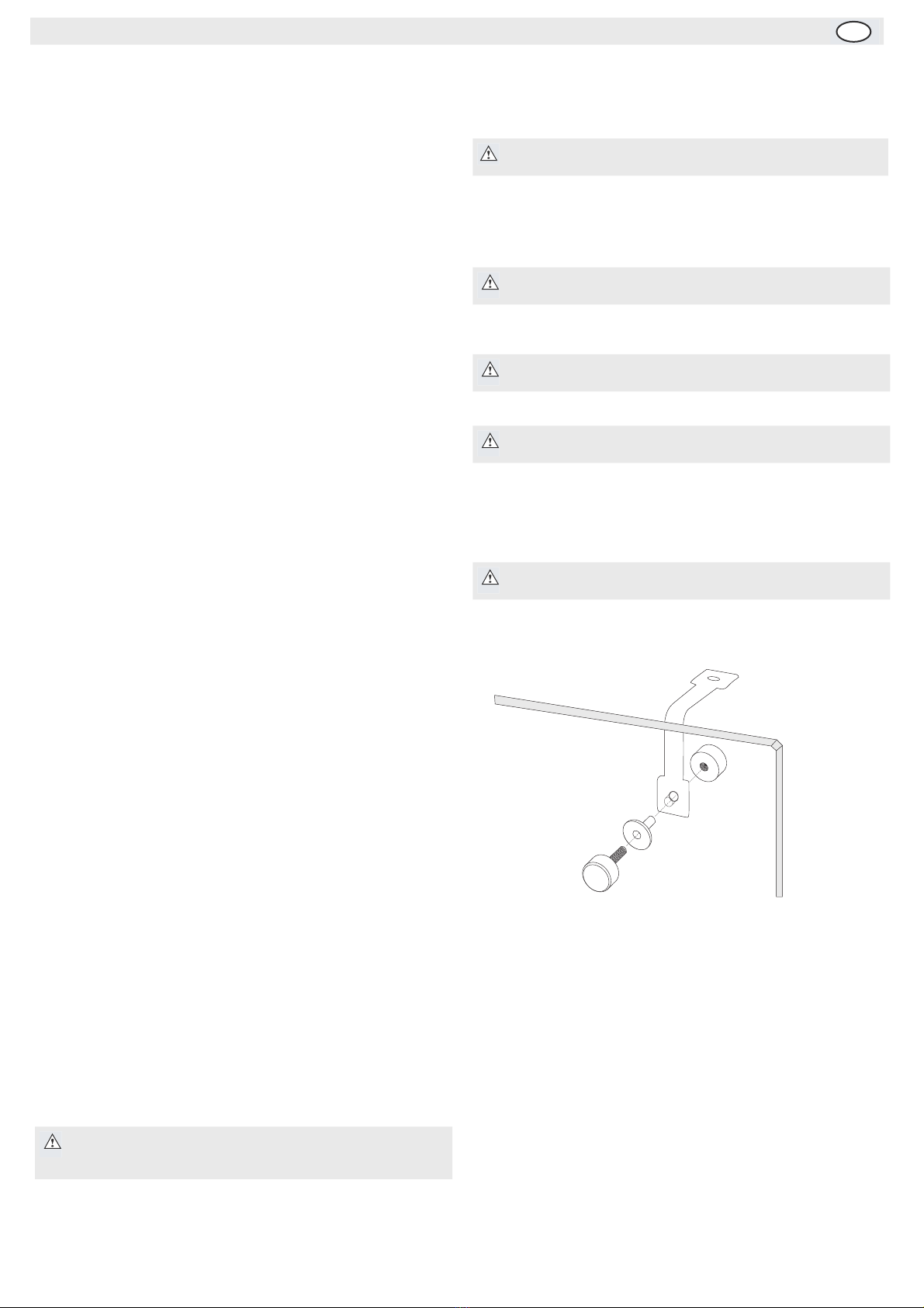
Fit Glass Panels
1. Screw the collars to the rim of the appliance.
2. Slot the two side panels into the collars, with the holes in the glass at
the top.
3. Screw a grub screw into each collar to secure the panels.
4. Slot the rear panel into the collars, with the holes in the glass at the top.
5. Screw a grub screw into each collar to secure the panel.
6. Slot the plastic plugs into each of the holes.
7. Screw the brackets to the inside of each pane using the bolt assemblies.
8. Place the top panel onto the brackets, ensuring all holes line up.
9. Insert the plugs and attach the top panel to the brackets with the bolt
assemblies (see below) .
Operation
Storing Food
To get the best results from your RWA appliance, follow these instructions:
• Only store foodstuffs in the appliance when it has reached the correct
operating temperature.
• Do not obstruct the fans inside the appliance.
Turn On
1. Ensure the power switch is set to [O] and turn on at the socket.
2. Switch on the Power [I]. The current temperature within the appliance
is displayed.
Note: If the unit has been stored in a non-vertical position,
stand it in an upright position for approximately 12 hours
before operation.
• RWA Refrigerator or Freezer
• Top glass panel
• Rear glass panel
• Side glass panels x 2
• Instruction manual
• Collars x 6
• Brackets x 7
• Grub screws x 7
• Screws x 12
• Plugs x 14
• Gastranorm adaptor bar
• Adjustable feet x 4
Note: Before using the appliance for the first time, clean the
internal cabinet and shelves with soapy water.
Note: Ensure the hole in the collar for the grub screw faces
inwards.
Note: Ensure the screw hole furthest from the edge of the
panel goes to the back of the appliance.
Note: Ensure the soft end of the grub screw is the end making
contact with the glass.
Note: Ensure the short end of the bolt assembly is on the
outside of the panels.

2
UK
Lock/Unlock the Control Panel
To lock the control panel:
1. Press and hold the UP and DOWN buttons simultaneously for 10 seconds.
2. Pof flashes on the display and the keyboard is locked.
To unlock the control panel:
1. Press and hold the UP and DOWN buttons simultaneously for 10 seconds.
2. Pon flashes on the display and the keyboard is unlocked.
Enter the Parameter Menu
1. Unlock the control panel, if locked.
2. Press and hold the SET button until ‘d1 ’ flashes on the display.
3. Press the SET button repeatedly to scroll to the desired parameter (see below).
Note:
If a button is not pressed for 10 seconds while using the control panel it times out and reverts to standby mode.
When parameters are being set the Setpoint LED will flash on the display.
Parameter Name Description Range
d1 Operating temperature Set the operating temperature of the appliance -2°C to 10°C
d2 Temperature
Differential
The Temperature Differential is the allowed temperature difference above and below the
operating temperature before the compressor starts/cuts off 0 to 20°C
d3
Temperature Range Set the minimum (d3) and maximum (d4) temperatures that the appliance can fluctuate
between
-40°C
d4 95°C
d5 Compressor Activation
Time Intervals Enter the minimum time interval between the compressor turning off after turning on. 0-999 seconds
d6 Maximum Temperature
Differential Alarm
Set an alarm to sound if the temperature inside the appliance exceeds the set operating
temperature by a specified amount 0°C-50°C
d7 Temperature
Differential Alarm Delay Set a delay before the temperature differential alarm is triggered 0-99 minutes
d8 Defrost Cycle Time
Intervals Set the time between each defrost cycle 1-999 hours
d9 Maximum Defrost
Duration
Set the maximum length of the defrost cycle
Note: The defrost duration can be overridden by parameter d10 (below), if the
cut-off temperature is reached before the end of the defrost duration
0-999 minutes
d10Defrost Cut-off
Temperature Set the defrost cut-off temperature -45°C to 50°C
d11Additional Cut-off
Defrost Period
Set an additional amount of defrost time after the defrost cut-off point has been reached (if
required) 0-99 minutes
d12Delayed Actual
Temperature Display
Set the length of time the inner temperature of the appliance (before defrost started) is
displayed for after a defrost cycle has finished 0-99 minutes
d13Compressor On/Off
During Defrost Turn the Compressor On or Off during the defrost cycle On (1) or Off (0)
d14Evaporator Drying Time Set the amount of time the compressor remains turned Off after a defrost cycle, reducing the
amount of frost build up 0-99 minutes
=19 Temperature Offset Should there be any variance between measured and actual temperature, the measured
temperature can be offset to compensate -20°C to 20°C

3
UK
Manual Defrost
The appliance will automatically run a defrost cycle every six hours.
To manually defrost the appliance:
1. Press and hold the DEFROST button for 5 seconds.
2. The defrost cycle will start immediately and the Defrost LED illuminates. The defrost will last a maximum of 30 minutes.
3. Waste water is collected in the waste water tray.
Cleaning, Care & Maintenance
• Switch off and disconnect from the power supply before cleaning.
• Clean the interior of the appliance as often as possible.
• Do not use abrasive cleaning agents. These can leave harmful residues.
• Clean the door seal with water only.
• Always wipe dry after cleaning.
• Do not allow water used in cleaning to run through the drain hole into the evaporation pan.
• Take care when cleaning the rear of the appliance. Sharp edges can cut.
• A RWA agent or qualified technician must carry out repairs if required.
Cleaning the Condenser
Periodically cleaning the condenser can extend the life of the appliance.
RWA recommend that a RWA agent or qualified technician clean the condenser.
Parameter Name Description Range
=22 Unit of Measurement Set whether the temperature is displayed in Centigrade or Fahrenheit Centigrade (0) or Fahrenheit (1)
=23 Compressor Operation
During Probe Failure Set whether the compressor runs or remains Off during a temperature probe failure
Compressor runs (1)
Remains Off until fault fixed (0)
Runs intermittently with
parameters =24 and =25 (2)
=24 Compressor ‘On’
Duration Set the length of time the compressor runs during a temperature probe failure 1-99 minutes
=25 Compressor ‘Off’
Duration Set the length of time the compressor remains Off during a temperature probe failure 1-99 minutes
=34 Initial Defrost After
Startup
Set whether the appliance starts a defrost cycle 10 minutes after startup or after the time
programmed in parameter d8 (Defrost Cycle Time Intervals)
Begins 10 minutes after startup
(0) or when programmed (1)
=38 Minimum Temperature
Alarm
Set the display to flash should the inner temperature of the appliance drop beyond a specified
point from the programmed operating temperature 1°C to 50°C
Note: The cycle starts from the time the appliance is initially powered up.
Note: Starting a manual defrost also resets the automatic defrost timer.
The next automatic defrost will start six hours after the manual defrost has finished.

4
UK
Troubleshooting
If your POLAR appliance develops a fault, please check the following table before making a call to the Helpline.
Error Messages
The following table details the cause and subsequent response of the appliance to errors.
The alarm message will end when the alarm trigger is no longer present, except PF1 and PF2 that require the appliance to be turned Off, then On again.
Technical Specifications
Fault Probable Cause Action
The appliance is not working
The unit is not switched on Check the unit is plugged in correctly and switched on
Plug and lead are damaged Call RWA agent or qualified Technician
Fuse in the plug has blown Replace the fuse
Power supply Check power supply
Internal wiring fault Call RWA agent or qualified Technician
The appliance turns on, but the
temperature is too high/low
Too much ice on the condenser Defrost the appliance
Condenser blocked with dust Call agent or qualified Technician
Doors are not shut properly Check doors are shut and seals are not damaged
Appliance is located near a heat source or air flow
to the condenser is being interrupted
Move the refrigerator to a more suitable location
Ambient temperature is too high Increase ventilation or move appliance to a cooler position
Unsuitable foodstuffs stored in the appliance Remove any excessive hot foodstuffs or blockages to the fan
Appliance is overloaded Reduce the amount of food stored in the appliance
The appliance is leaking water
The appliance is not properly levelled Adjust the screw feet to level the appliance
The discharge outlet is blocked Clear the discharge outlet
Movement of water to the drain is obstructed Clear the floor of the appliance
The water container is damaged Call RWA agent or qualified Technician
The drip tray is overflowing Empty the drip tray
The appliance is unusually loud
The frame has become loose Check and tighten all nuts and screws
The appliance has not been installed in a level or
stable position
Check installation position and change if necessary
Error Message
(flashing) Cause Appliance Response Action
HtAThe inner temperature exceeds
the set maximum temperature
Display flashes
Alternating error message and current temperature
Check Troubleshooting Guide
If problem persists call RWA agent or
qualified Technician
LtAThe inner temperature exceeds
the set minimum temperature
Display flashes
Alternating error message and current temperature
Check Troubleshooting Guide
If problem persists call RWA agent or
qualified Technician
PF1Short circuit or interruption of
the thermostat probe input line Display flashes Compressor operates as specified by
parameter ‘=23 ’
PF2Short circuit or interruption of
the evaporator probe input line Display flashes Defrost as specified by parameters d8 and d9
HLA Inner temperature greater than
90°C
Display flashes
Alternating error message and current temperature Call RWA agent or qualified Technician
LLAInner temperature lower than
-45°C
Display flashes
Alternating error message and current temperature Call RWA agent or qualified Technician
Model Voltage Power Current Temperature
Range Capacity Refrigerant Dimensions
H x W x D (mm)
Weight
(Kg)
VRX1200/330
VRX1500/330
VRX1800/330
VRX2000/330
230V 50Hz 250W 1.1A 2°C to 10°C 5 x Gastranorm ¼ Container 430 x 1200 x 335
230V 50Hz 250W 1.1A 2°C to 10°C 7 x Gastranorm ¼ Container 430 x 1500 x 335
230V 50Hz 250W 1.1A 2°C to 10°C 9 x Gastranorm ¼ Container R134a 430 x 1800 x 335
230V 50Hz 250W 1.1A 2°C to 10°C 10 x Gastranorm ¼ Container R134a 430 x 2000 x 335

5
UK
Electrical Wiring
RWA appliances are supplied with a 3 pin, moulded, BS1363 plug and lead, with a 13 amp fuse as standard.
The plug is to be connected to a suitable mains socket.
RWA appliances are wired as follows:
• Live wire (coloured brown) to terminal marked L
• Neutral wire (coloured blue) to terminal marked N
• Earth wire (coloured green/yellow) to terminal marked E
All RWA appliances must be earthed, using a dedicated earthing circuit.
If in doubt consult a qualified electrician.
Electrical isolation points must be kept clear of any obstructions. In the event of any emergency disconnection being required they must be readily accessible.
Compliance
BUFFALO parts have undergone strict product testing in order to comply with regulatory standards and specifications set by international, independent, and
federal authorities.
BUFFALO products have been approved to carry the following symbol:

This manual suits for next models
3
Table of contents
Other Anvil Refrigerator manuals