AOpen AK33 M Datasheet

Support 4 USB Port
CD-IN Connecto
r
A
U
X
-IN Connector
MODEM-CN Connecto
r
Front Audio Connector
PCI Slot x 6
(PCI 6 supports slave mode PCI cards only)
FDC
COM2
2Mbit Flash ROM
Full-time
Virus Protection
Wake On RTC Time
r
2rd USB Port
WOL
Wake On LAN
Dr. LED
System Thermal Sensor Connector
Chassis Fan Connector with
H/W Monitoring Function
Battery-less & Long-life Design
IrDA Connector Front Panel
Connector
A
TA66/100 IDE Bus Suspend to HDD
JP14 Clear CMOS
A
TX Power Connecto
r
PC133 DIMM
Suspend to RAM
RAM Power LED
VIA ProSavage™ KM133 / KM133A
Chipset
200/266 MHz
462-pin CPU Socket with Voltage
and Frequency Auto-Detection
that supports AMD®Athlon®and
Duron®600MHz~1.3GHz+ CPU
CPU Thermal Sensor
CPU Fan Connector
with H/W Monitoring Function
Low ESR Capacitor
Resettable Fuse
PC99 Back Panel
4x AGP Expansion Slot
MIC-In
PS/2 Mouse
Connector
PS/2 Keyboard
Connector
USB Port
SPP/EPP/ECP
Parallel Port
COM 1 Port VGA
Connector
MIDI/Game
Port
Line-In
Speaker
Out
JP21 FSB Select Jumper (AK33M(A) only)

80-Wire IDE Cable x 1
Hard Drive IDE cable x 1
Floppy Drive cable x 1
COM2 Cable x 1
Bonus Pack CD disc x 1
This Easy Installation Guide x 1
Everything you need to boot this
motherboard is included in this Easy
Installation Guide. For more
information, a complete Online User's
Manual can be found in the Bonus
Pack CD Disc. Thanks for the help of
saving our earth.
1. System / CPU Thermal Solution
With the increasing performance of system, the components nowadays always generate enormous heat in
your system, such as CPU, VGA card, HDD, and so on. This motherboard provides two thermal solutions
for users to detect the temperature of any components, which respectively are system thermal senso
r
connector and CPU thermal sensor inside CPU socket.
Tip: When should I Clear CMOS?
1. Boot fail because of overclocking…
2. Forget password…
3. Troubleshooting…
You can clear CMOS to restore system default setting.
To clear the CMOS, follow the procedure below.
1. Turn off the system and unplug theAC power.
2. Remove ATX power cable from connector PWR2.
3. Locate JP14 and short pins 2-3 for a few seconds.
4. Return JP14 to its normal setting by shorting pins 1-2.
5. Connect ATX power cable back to connector PWR2.
Clear CMOS
3
2
1
Normal Operation
(default)
3
2
1
2. JP14 Clear CMOS
PART NO: 49.89102.001 DOC. NO: AK33MA-EG-E0105B
System Thermal Sensor Connector
CPU Thermal Sensor
GND 1
2
Sensor

CPU Ratio Auto detect (depends on JP21 FSB selection)
CPU FSB
(By keying in your preferable
Frequency within the range)
FSB=100 MHz, 100~133 MHz
FSB=133 MHz, 133~166 MHz
CPU CPU Core
Frequency EV6 Bus Clock Ratio
Duron 700 700MHz 200MHz 7.0x
Duron 750 750MHz 200MHz 7.5x
Duron 800 800MHz 200MHz 8.0x
Duron 850 850MHz 200MHz 8.5x
Athlon 750 750MHz 200MHz 7.5x
Athlon 800 800MHz 200MHz 8.0x
Athlon 850 850MHz 200MHz 8.5x
Athlon 900 900MHz 200MHz 9.0x
Athlon 950 950MHz 200MHz 9.5x
Athlon 1G 1GHz 200MHz 10.0x
Athlon 1.1G 1.1GHz 200MHz 11.0x
Athlon 1.2G 1.2GHz 200MHz 12.0x
Athlon 1G 1GHz 266MHz 7.5x
Athlon 1.13G 1.13GHz 266MHz 8.5x
Athlon 1.2G 1.2GHz 266MHz 9.0x
Athlon 1.3G 1.3GHz 266MHz 9.5x
4. Installing CPU and Fan
Plug CPU to AMD Socket 462 connector. Be
careful of CPU orientation. Plug in the fan
cable to the 3-
p
in CPU FAN or FAN connector.
Note: Some CPU fans do not have
sensor pin, so that cannot support
fan monitorin
g
.
3. Front Audio
If the housing has been designed with an audio port on the front panel, you’ll be able to
connect onboard audio to front panel through this connector. By the way, please remove
5-6 and 9-10 jumper caps from the Front Audio Connector before connecting the cable.
Please do not remove these 5-6 and 9-10 yellow jumper caps if there’s no audio port on
the front panel.
SENSOR
+12V
GND
GND
+12V
SENSOR
HPIN_L
KEY
HPIN_R
VCC
GND
HPOUT_L
NC
HPOUT_R
MIC_VREF
MIC
2 1
10 9
5. Setting CPU Voltage and Frequency
Full-range Auto-Detect CPU Core Voltage
This motherboard supports CPU VID function. The CPU core voltage will be
automatically detected and the range is from 1.1V to 1.85V.
Supported CPU Frequency
Core Frequency = CPU Bus Clock * CPU Ratio
EV6 Bus Speed = CPU Bus Clock x 2
PCI Clock = CPU Bus Clock / Clock Ratio
A
GP Clock = PCI Clock x 2
Warning: VIA®ProSavage KM133 / KM133A chipset supports
100/133MHz FSB and 66MHz AGP clock with CPU running at 100MHz (If
CPU runs at 133MHz, VIA®ProSavage KM133A chipset can supports
133MHZ FSB and 66 MHz AGP clock only), higher clock setting may
cause serious s
y
stem dama
g
e.
Tip: If your system hangs or fails to boot because of overclocking,
simply use <Home> key to restore the CPU default frequency.

9. Connecting IDE and Floppy Cable
Connect 34-pin floppy cable and 40-pin IDE cable to floppy connector FDC and IDE
connector. Be careful of the pin1 orientation. Wrong orientation may cause system
damage.
A
ttach the power LED, speaker, and reset
switch connectors to the corresponding pins.
If you enable “Suspend Mode” item in BIOS
Setup, the ACPI & Power LED will keep
flashing while the system is in suspend
mode.
7. Connecting Front Panel Cable
Locate the power switch cable from you
r
A
TX housing. It is 2-pin female connecto
r
from the housing front panel. Plug this
connector to the soft-power switch
connector marked SPWR.
Pin 1
Slave (4th)
Master (1st)Slave (2nd)
Master (3rd)
IDE2 (Secondary)
IDE1 (Primary)
FDC
Pin 1
1
Speaker
HDD LED
Keylock
+
+
+
+
SPWR
+
+ ACPI &
Power LED
Reset
1
SPWR
GND
ACPI & PWR LED
GND
+5V
NC
NC
GND
RESET
GND
GND
KEYLOC
K
+5
V
HDD LED
HDD LED
+5
V
+5
V
GND
NC
SPEAKE
R
6. JP21 FSB Select Jumper
FSB 133MHz
3
2
1
FSB 100MHz
(default)
3
2
1
This JP21 jumper is used to specify the relationship of PCI and FSB clock. Please set the
j
umper based on your CPU FSB. For CPU FSB of 100MHZ, you may set JP21 to “1-2”
pin and for CPU FSB of 133MHz, you may set the pin to “2-3”.
8. Dr. LED (Optional)
The Dr. LED can easily show what kind of problems you may incur on your system during
assembly. It can clearly indicate whether there is a component issue or an installed issue
by the 8 LEDs on the front panel of PC-Doctor. This can helps you quickly self-diagnose
your system status.
GP014
GP011
GP012
1
2
5
6
3.3V
KE
Y
GND

12. Connecting 2nd USB Port
10. Connecting IrDA Connector
The IrDA connector can be configured to support wireless infrared module, with this
module and application software such as Laplink or Windows 95 Direct Cable Connection,
the user can transfer files to or from laptops, notebooks, PDA devices and printers. This
connector supports HPSIR (115.2Kbps, 2 meters) and ASK-IR (56Kbps).
Install the infrared module onto the IrDA connector and enable the infrared function from
BIOS Setup, UART mode select, make sure to have the correct orientation when you plug
in the IrDA connector.
This motherboard supports four USB ports. Two of them are on back panel connector,
the other two are on the left-bottom area of this motherboard. With proper cable, you
can connect them to front panel.
Pin 1
Pin 1
11. Connecting CD-IN / AUX-IN / MODEM -CN
The CD-IN connector is used to connect
CD Audio cable from CDROM or DVD
drive to onboard sound.
The AUX-IN connector is used to connect
MPEG Audio cable from MPEG card to
onboard sound.
The MODEM-CN connector is used to
connect Mono IN/MIC Out cable from
internal modem card to onboard sound
circuit.
CD-IN (Black)
MODEM-CN (Red)
AUX-IN (Green)
Connector Pin1 Pin2 Pin3 Pin4
CD-IN Right GND GND Left
AUX-IN Left GND GND Right
MODEM-CN Mono In GND GND Mic Out
1 2
9 10
+5V
SBD3-
SBD3+
GND
NC
+5V
SBD2-
SBD2+
GND
KEY
KEY GND
+5V
NC
IRRX
IRTX
Warning: If you want
to uninstall the VIA
A
GP Vxd driver,
p
lease remove the
A
GP card driver first.
Otherwise, the screen
may go black at
rebooting after the
un-installation.
Note: Installing this
Bus Master IDE
driver may cause
Suspend to Hard
Drive failure.
13. Installing VIA 4 in 1 driver
You can install the VIA 4 in 1 driver, VIA ATAPI Vendor Support Driver, VIA AGP, IRQ
Routing Driver, VIA Registry (INF) Driver) from the Bonus Pack CD disc Autorun menu.

14. Power-on and Load BIOS Setup
A
fter you finish the setting of jumpers and connect correct cables. Powe
r
on and enter the BIOS Setup, press <Del> during POST (Power-On
Self Test). Choose "Load Setup Defaults" for recommended optimal
performance.
Del
15. Autorun Menu from Bonus CD Disc
You can use the autorun menu of Bonus CD disc. Choose the utility and driver and select
model name.
17. BIOS Upgrade
A
Open Easy Flash is a little different than traditional flash method. The BIOS binary file
and flash routine are linked together and you simply run a single commend to complete
the flash process.
Below are the steps for easy flashing procedures: (applies for Award BIOS ONLY)
1. Download new BIOS upgrade zipped file from AOpen's web site.
For example, AK33M102.ZIP.
2. Run shareware PKUNZIP (http://www.pkware.com/) which supports miscellaneous
operation systems to extract the binary BIOS file and the flash utility.
Or Winzip (http://www.winzip.com/) in Windows environment.
3. Save the unzipped file into a bootable floppy disk.
For example, AK33M102.BIN & AK33M102.EXE
4. Reboot the system to DOS mode without loading any memory handler (such as
EMM386) or device driver. It needs around 520K free memory space.
5. Execute A:> AK33M102 and the program will do the rest of it.
DO NOT turn off the power during FLASH PROCESS until you are asked to!!
6. Reboot system and press <Del> to enter BIOS setup, Choose “Load Setup
Defaults"
,
then “Save & Exit Setu
p
”. Done!
16. Installing Onboard Sound Driver
This motherboard comes with an AD 1885 AC97 CODEC and the sound controller is in
VIA South Bridge chipset. You can find the audio driver from the Bonus Pack CD disc
autorun menu.
Warning: The upgrade of new BIOS will permanently replace your original BIOS
content after flashing. The original BIOS setting and Win95/Win98 PnP information
will be refreshed and you probably need to re-configure your system.
Warning: Please avoid of using "Load
Turbo Defaults", unless you are sure
your system components (CPU, DRAM,
HDD, etc.) are good enough for turbo
settin
g
.

If you encounter any trouble to boot you system, follow the
procedures accordingly to resolve the problem.
Part Number and Serial Number
The Part Number and Serial number are printed on bar code label. You can find this ba
r
code label on the outside packing, on ISA/CPU slot or on component side of PCB. Fo
r
example:
Model name and BIOS version
AK33M / AK33M (A)R1.00 Feb.01.2001 AOpen Inc.
A
ward Plug and Play BIOS Extension v1.0A
Copyright © 1998, Award Software, Inc.
Model name and BIOS version can be found on upper left corner of first boot screen (POST
screen). For example:
P/N: 91.88110.201 is part number, S/N: 91949378KN73 is serial number.
Make sure if the jumper settings for CPU and DRAMs are correct.
Clear CMOS.
Install the VGA card. Then connect your monitor and keyboard.
The problem was probably caused
by power supply or motherboard
failure. Please contact your reselle
r
or local distributor for repairing.
Perhaps your VGA card or monito
r
is defective.
No
Yes
No
Yes
It is very possible that your keyboard
is defective.
During system rebooting, press Del to enter BIOS Setup. Choose
“Load Setup Default".
The problem should be caused by the
IDE cables or HDD itself.
Re-install Windows 95, Windows 98 or Windows NT.
Yes
Yes
Turn off the power and unplug the AC power cable, then remove all
of the addon cards and cables, including VGA, IDE, FDD, COM1,
COM2 and Printer.
Turn on the power, and check if
the power supply and CPU fan
work properly.
Start
Check if there is display.
Press Ctrl, and Alt key at the
same time, hold them and then
press Del to see if the
s
y
stem reboots.
Turn off the system and
re-connect the IDE cable.
Check if the system can
reboot successfully.
End
No
No AK33M / AK33M (A) is model name of motherboard, R1.00 is BIOS version.
Part No. Serial No.
Part No. Serial No.

Dear Customer,
Thanks for choosing AOpen products. To provide the best and fastest service to
our customer is our first priority. However, we receive numerous emails and
p
hone-calls worldwide everyday, it is very hard for us to serve everyone on time.
We recommend you follow the procedures below and seek help before contact us.
With your help, we can then continue to provide the best quality service to more
customers.
Thanks very much for your understanding!
A
Open Technical Supporting Team
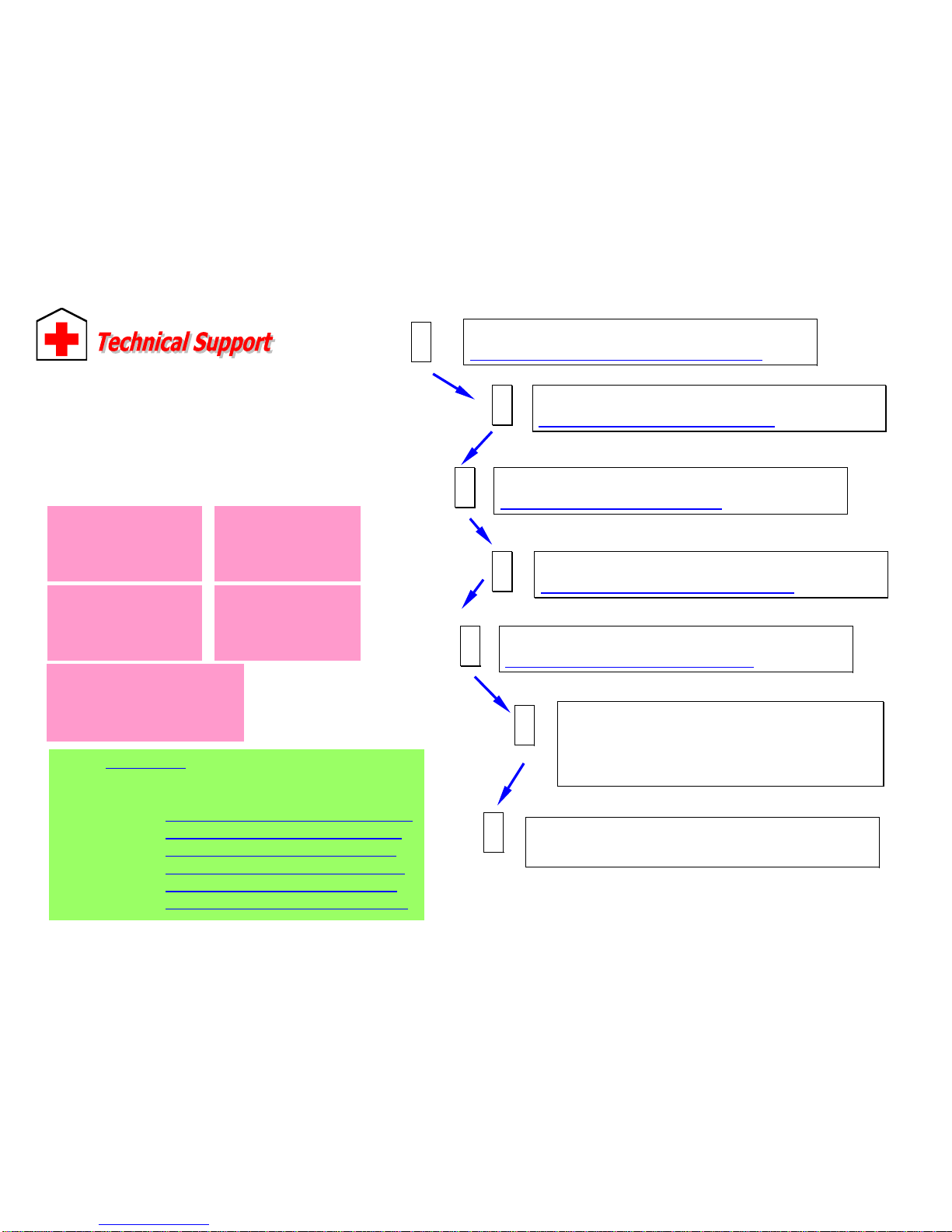
Online Manual: Please check the manual carefully and make sure the
jumper settings and installation procedure are correct.
http://www.aopen.com.tw/tech/download/manual/default.htm
1
1
Test Report: We recommend to choose board/card/device from the
compatibility test reports for assembling your PC.
http://www.aopen.com.tw/tech/report/default.htm
2
2
FAQ: The latest FAQ (Frequently Asked Questions) may contain a
solution to your problem.
http://www.aopen.com.tw/tech/faq/default.htm
5
5
Download Software: Check out this table to get the latest updated
BIOS/utility and drivers.
http://www.aopen.com.tw/tech/download/default.htm
3
3
News Group: Your problem probably had been answered by our support
engineer or professional users on the news group.
http://www.aopen.com.tw/tech/newsgrp/default.htm
4
4
Contact Distributors/Resellers: We sell our products through
resellers and integrators. They should know your system
configuration very well and should be able to solve your problem
more efficiently than us. After all, their attitude of service is an
important reference for you if next time you want to buy something
else from them.
6
6
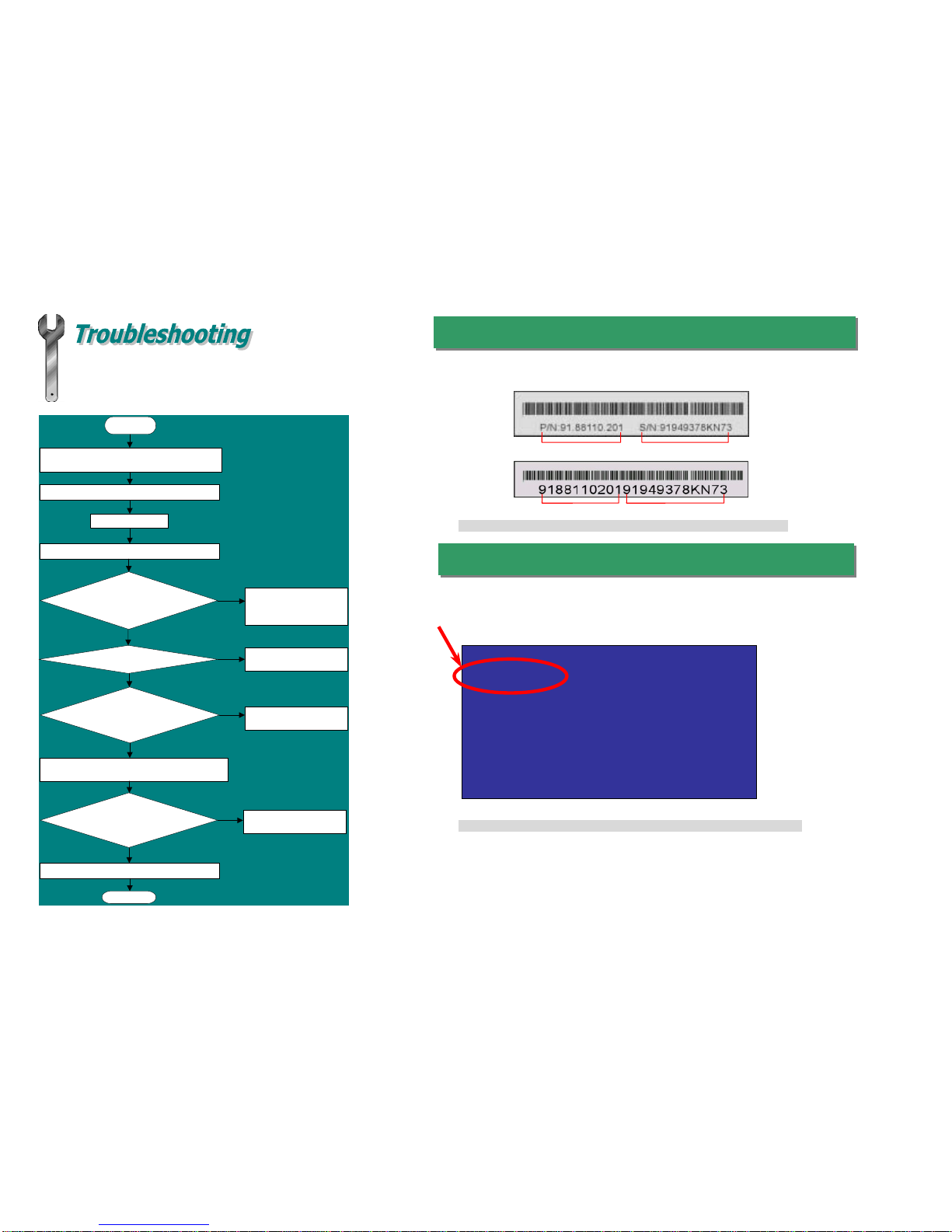
Contact Us : Please prepare detail system configuration and error
symptom before contacting us. The part number, serial number and BIOS
version are also very helpful.
7
7
Web Site: www.aopen.com
E-mail: Send us email by going through the contact form below.
English http://www.aopen.com.tw/tech/contact/techusa.htm
Japanese http://aojp.aopen.com.tw/tech/contact/techjp.htm
Chinese http://w3.aopen.com.tw/tech/contact/techtw.htm
German http://www.aopencom.de/tech/contact/techde.htm
French http://aofr.aopen.com.tw/tech/contact/techfr.htm
Simplified Chinese http://www.aopen.com.cn/tech/contact/techcn.htm
Pacific Rim
A
Open Inc.
Tel: 886-2-2696-1333
Fax: 886-2-8691-2233
A
merica
A
Open America Inc.
Tel: 1-510-498-8928
Fax: 1-408-922-2935, 1-408-432-0496
Europe
A
Open Computer b.v.
Tel: 31-73-645-9516
Fax: 31-73-645-9604
Germany
A
Open Computer GmbH.
Tel: 49-2102-157700
Fax: 49-2102-157799
China
艾尔鹏国际上海(股)
有限公司
Tel: 49-2102-157700
Fax: 49-2102-157799
Other manuals for AK33 M
3
This manual suits for next models
1
Table of contents
Other AOpen Motherboard manuals

AOpen
AOpen AP57 User manual

AOpen
AOpen D X37PU-EG-E0110A Datasheet

AOpen
AOpen MX36LE-U Datasheet

AOpen
AOpen VKM400AM-S User manual

AOpen
AOpen MK73LE Setup guide

AOpen
AOpen DX34 Plus User manual

AOpen
AOpen AP43 User manual

AOpen
AOpen AX37D Plus Datasheet

AOpen
AOpen MX4GR Setup guide

AOpen
AOpen MK77 User manual

AOpen
AOpen AX45-4D MAX Datasheet

AOpen
AOpen AX4SG-GN Datasheet

AOpen
AOpen i915Ga-EFRII Datasheet

AOpen
AOpen AX4T II-533 Setup guide

AOpen
AOpen AX3S-1394 User manual

AOpen
AOpen DXPL-U Setup guide

AOpen
AOpen AK89 MAX User manual

AOpen
AOpen MX4GE Setup guide

AOpen
AOpen AX4B-533 Plus Datasheet

AOpen
AOpen AP5VM User manual