AP Diving HUS Operator's manual

Issue 1
HUS (Head Up Screen)
User Instruction Manual

A P D i v i n g H U S P a g e | 2
Contents
HUS –Head Up Screen .........................................................................................................3
HUS Features ........................................................................................................................4
Important Information.............................................................................................................4
Parts Supplied........................................................................................................................5
HUS Configuration .................................................................................................................6
HUS Assembly / Mounting......................................................................................................7
Pre-Dive / Surface Mode......................................................................................................10
Dive Mode............................................................................................................................12
Ceiling Height and Violation .................................................................................................15
Ascent Rate..........................................................................................................................17
Setpoint and Battery Icons ...................................................................................................18
Optional Connectivity ...........................................................................................................19
Warnings..............................................................................................................................20
Maintenance.........................................................................................................................22
Technical Data.....................................................................................................................23
EC TYPE Approval...............................................................................................................24
EC PPE Article 11B Approval...............................................................................................24
Manufacturer........................................................................................................................24
WARNING. These user instructions do not replace the AP Diving Rebreather
Manual in any way and do not explain the full rebreather functionality. These
instructions will detail the HUS as part of the rebreather system only.
WARNING. The HUS has optics that are designed for use underwater and as
such the display is remarkably clearer underwater than on the surface. On
the surface you have to focus on the display, however underwater, there is
no need to focus at all, the complete display is in focus at all times.

A P D i v i n g H U S P a g e | 3
HUS –Head Up Screen
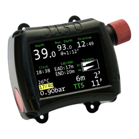
AP Diving’s HUS or Head Up Screen (RB130) is a near-eye, hands free secondary
display that shows the diver real-time information directly from the rebreather’s
oxygen controller electronics. The clever underwater optical lens magnifies the
display so it appears as if it is a 15”TV approximately 1 metre away. This gives live
rebreather information in the line of sight for the complete dive, without the need to
refocus. For many prescriptions normally removing the need for special masks or
lenses to compensate for poor eyesight. The HUS has been specially developed for
use with AP Diving’s range of rebreathers, equipped with Vision electronics and is
intended as an upgrade for existing customers as well as an optional item with new
AP Diving rebreathers.
The HUS is mounted on the rebreather mouthpiece using an adjustable articulated
mounting arm allowing bespoke positioning of the device to give the optimal view of
the display without compromising the diver’s vision of the diving environment. Due to
the mounting being so close to the mask, the HUS can be read in very low visibility
conditions where the conventional wrist mounted primary display would be more
awkward to read. This style of display also allows true hands free diving whilst still
monitoring the rebreather at all times. Excellent for photographers, videographers
and people who require two hands to work or play underwater.
The full colour display conveys all the key rebreather information with the added
benefit of conditional colouring to highlight the current status of the information
provided.
The HUS is driven by a bespoke I2C channel, the same I2C connection that delivers
the display information to the Handset. For this reason the HUS is provided in
addition to the HUD, as the HUD is driven by raw PPO2values direct from the oxygen
controllers and therefore can be used to fly the rebreather in the unlikely event of an
I2C communication failure.
1 metre
15” TV

A P D i v i n g H U S P a g e | 4
HUS Features
For use with all AP Diving Rebreathers using Vision Electronics with firmware
Version 06.00.00 and onwards installed
Displays real-time information directly from the rebreather’s oxygen controllers
Displayed data includes depth, time, decompression obligation, PPO2values,
setpoint, Setpoint switch method, battery status and more
All rebreather warnings communicated directly to the divers eye
Additional graphical display of ascent rate and ceiling height
Intuitive graphical layout complements the existing rebreather handset
Hands free rebreather monitoring in the line of sight without the need to refocus
No need for prescription masks or lenses to compensate for poor eyesight for
most prescriptions
Excellent readability even in very poor visibility conditions
Full colour display with conditional colouring
Secondary display, giving extra system redundancy
Low power consumption and powered by the Vision rebreather lid batteries
guaranteeing seamless power supply
Flexible mounting through articulated arm and therefore suitable for all types of
half and full face masks
Driven off one I2C bus arm giving appropriate isolation security from other
peripherals
Type Tested for CE approval according to the EN14143:2013 Rebreather standard
(Notified Body: SGS United Kingdom Ltd)
Important Information
DO: Read the instruction manual fully before using the rebreather
DO: Carry out all pre-dive checks prior to each dive
DO: Protect the HUS against shock at all times and avoid scratches on the
lens by replacing the lens protector if it starts to peel
DO: Make sure that the HUS is free from mechanical damage and that the
lens is not impeded in any way that could affect its use
DO: Wash the HUS with fresh water after each dive to avoid any salt or dirt
build up
DO NOT: Ignore warnings displayed by the HUS
DO NOT: Dive without sufficient battery power or enter the water until the
rebreather is correctly calibrated and in surface mode
DO NOT: Mount the HUS in any way that obstructs the use of other rebreather
functions, such as operating the mouthpiece / OCB, or the view of the
handset
DO NOT: Attempt to open the HUS as it is designed as a sealed unit
DO NOT: Attempt to modify the rebreather and HUS in any way
DO NOT: Use chemicals to clean the HUS

A P D i v i n g H U S P a g e | 5
Parts Supplied
Note: The HUS is a sealed potted unit and no attempt should be made to
disassemble the housing in any way. Trying to do so could cause irreversible
damage to the display and electronics.
RB130/5 HUS
Lens Protector
(supplied fitted)
RB131 HUS
Mounting Arm
RB130 HUS
(Factory fitted to
the Rebreather
Lid through a new
buzzer housing)

A P D i v i n g H U S P a g e | 6
HUS Configuration
HUS Display
Lens and Lens
Protector
Optical Lens
Mounting Arm
Articulated Segment
Cable Strain Relief
HUS Programming
Contacts (Factory
guidance required)
Cable from
Rebreather
Lid via Buzzer
Housing
Mounting Arm
Hose Clip

A P D i v i n g H U S P a g e | 7
HUS Assembly / Mounting
The HUS comes factory fitted to the Rebreather Lid. It is wired into the controllers
through a new buzzer housing. The rebreather firmware must be V06.00.00 or higher
for the HUS to work and this will be installed as standard. We recommend that the
HUS is assembled within the Rebreather using the following procedure:
1. Compress exhale mouthpiece hose next to the mouthpiece hose fittings
2. Whilst compressed, thread the HUS mounting arm over the hose
HUS Mounting Arm

A P D i v i n g H U S P a g e | 8
3. Slide the mounting arm onto the hose fitting where it should snap into place
4. Prior to mounting the HUS, it is recommend that the HUS cable is wrapped
around the convoluted hose to prevent the cable from becoming a snag
hazard. Depending on the rebreather setup and hose lengths, it may be
necessary to wrap the cable around several times to take up extra length.
5. Slide the HUS into the mounting arm from the front until the clip is at the
bottom of the HUS barrel

A P D i v i n g H U S P a g e | 9
6. Rotate the mounting arm around the hose fitting and manipulate the
articulated arm to position the HUS into an approximate position (as if it would
point towards the mask)
7. When wearing the unit reposition the HUS to the desired position for your
particular mask and preferences.
The nature of the articulated arm means that very fine position adjustments are
possible, and alterations can be made at any time prior to or during the dive. The
HUS arm length can be adjusted by removing or adding push-together sections.

A P D i v i n g H U S P a g e | 10
Pre-Dive / Surface Mode
Whilst the rebreather goes through its start-up process and self-tests, the HUS
displays the AP Diving logo.
During this time the diver will be looking at the primary display (handset) and
confirming the electronic checklist.
5.7v
BATTERY TEST
5.8v
Handset
Display
HUS
Display

A P D i v i n g H U S P a g e | 11
Following a successful calibration the HUS will display the ‘Surface Mode’screen:
The HUS has been laid out in a very similar fashion to the handset so it is very
intuitive for existing users and there is no confusion when alternating between the
two displays. The HUS uses high contrast colours to help highlight important
information as well as the status of the rebreather. In general terms white and green
are good, red is used to highlight conditions that are important to the diver. i.e. when
battery has low voltage, when they ascend too fast or have a warning of any sort.
Yellow is used as an intermediate condition for decompression condition and ascent
rate.
The ‘Surface Mode’is identified by the time and atmospheric pressure. These will
change to show dive time, depth and deco obligation once sufficient depth is reached
for the rebreather to enter ‘Dive Mode’ i.e. 1.2m
Master Controller
PPO2Values
Setpoint Switch
Method
Time
Setpoint
Battery Status
Gas Type
Atmospheric
Pressure
13:48:27 1003mB
0.98 0.99 0.98
0.70
C1
DIL3 10/70

A P D i v i n g H U S P a g e | 12
Dive Mode
No Stop Time (NST) Display
Until sufficient depth and time causes a decompression obligation, the handset and
HUS show a no stop time (NST) along with the dive time and current depth.
The no stop time is shown in green, meaning there is currently no decompression
required. The scrubber monitor and battery status are also in green showing a good
condition. All other information in this example are shown in white as they are all
within the appropriate limits.
In an attempt not to crowd the HUS display, it does not display max depth, current
gas, any CCR and DECO menus or functions found by pressing and holding buttons.
These are however still shown on the handset.
Scrubber Monitor
Dive Time
No Stop Time
Ascent Rate
Current Depth
124 23.3ft
0.72 0.69 0.73
0.70
C1
48:27 DIL3 10/70 35.0

A P D i v i n g H U S P a g e | 13
Time To Surface (TTS) Display
When sufficient depth and time causes a decompression obligation, the handset and
HUS show a time to surface (TTS) along with the dive time, current depth and a
ceiling height that the diver should not exceed.
The time to surface and ceiling height are shown in yellow, highlighting the
decompression obligation currently in place. The HUS also shows a graphical
representation of the ceiling height in relation to the current depth. This is the curve
on the left of the display and is explained later in this manual.
The scrubber monitor and B1 battery status in this example are in red showing a low
battery issue and poor condition of the CO2scrubber.
Ceiling Height in
relation to Depth
Dive Time
Time To Surface
Ceiling Height
Current Depth
48TTS 13.5 43.3m
1.30 1.32 1.32
1.30
C1
108:27 DIL3 10/70 50.0

A P D i v i n g H U S P a g e | 14
Estimated Time To Surface (EST) Display
When the current depth has been shallower than the ceiling height for more than 2
minutes (a ceiling violation), the TTS will be replaced with an EST (estimated time to
surface).
The estimated time to surface and ceiling height are shown in red, highlighting the
fact that the decompression is now estimated due to the ceiling violation.
28EST 13.5 13.3m
1.30 1.32 1.32
1.30
C1
108:27 DIL3 10/70 50.0
Ceiling Height in
violation
Dive Time
Estimated Time
To Surface
Ceiling Height
Current Depth

A P D i v i n g H U S P a g e | 15
Ceiling Height and Violation
Ceiling Height
Both the HUS and rebreather handset display ceiling height as a numerical value
(either in metres or feet) However, the HUS also has a graphical representation for
this on the left of the display.
The green shows the ‘Ceiling Height’ in relation to the ‘Current Depth’. This is
continually updated throughout the dive once decompression is incurred and until no
other stops are required, when the grey graphic will extend to the bottom of the
screen.
Surface to Ceiling
Current Depth
Ceiling Height
Current Depth
No Ceiling
No Stop Time

A P D i v i n g H U S P a g e | 16
Ceiling Violation
When the current depth has been shallower than the ceiling height for more than 2
minutes, the ceiling violation will be shown with a full red curve on the left as well as
the normal ‘Ceiling Violation’ warning across the display.
Ceiling Height
in violation
Ceiling Height
Current Depth

A P D i v i n g H U S P a g e | 17
Ascent Rate
The ascent rate is represented graphically on the right of the display.
When ascending at a rate of less than 5m/min the bar graph will be green.
As the ascent rate increases the graphic extends higher and turns yellow when the
ascent rate is between 5 and 10m/min.
When ascending at a rate above 10m/min the bar graph will be red and you will see
the ‘- -SLOW - - ’ warning.
Ascent Rate

A P D i v i n g H U S P a g e | 18
Setpoint and Battery Icons
The Setpoint Switch Mode icons are shown below, manual, automatic, gradual and
forced low (respectively). If the diver selects to switch to Open Circuit on the handset,
the ‘OC’ symbol will replace the setpoint mode icon.
Battery Icons
The HUS incorporates the same highlighted frame to indicate which battery is the
master. (providing power to the solenoid and display)
Conditional colouring is used to help highlight a low battery condition
Master Controller
Setpoint Switch
Method
Setpoint
Battery Status
B1 & B2
B1
B2

A P D i v i n g H U S P a g e | 19
Optional Connectivity
There are various options that can be used with AP diving rebreathers and these
options are highlighted on the HUS as well as the handset.
The Scrubber Monitor is displayed in the same way as the handset but with the
added benefit of conditional colouring. When the active area of the scrubber is
becoming low the bar will change from green to red to highlight this issue.
If a scrubber monitor is not fitted, but a CO2Sensor is present then ‘++++’ is
displayed.
If neither a scrubber monitor nor CO2sensor is fitted then ‘- - - -’ is displayed.
Scrubber Monitor
Conditional
Colouring
CO2Sensor fitted
No options fitted

A P D i v i n g H U S P a g e | 20
Warnings
Warnings are shown on both the handset and the HUS.
The HUS displays which Controllers (or Batteries) are generating the warning as well
as conditionally colouring the related information red –in this case the PPO2values.
LOW BATTERY
1.30 1.32 1.32
1.30
C1
B1
Warning
Description
Battery with
warning
Conditional
Colouring
Warning
Description
Controllers with
warning
Conditional
Colouring
Table of contents
Other AP Diving Diving Instrument manuals

AP Diving
AP Diving Back Mounted Counterlungs Operator's manual

AP Diving
AP Diving AP100 User manual

AP Diving
AP Diving Commando Escape Operator's manual

AP Diving
AP Diving Pocket Reel User manual

AP Diving
AP Diving RB111 Operator's manual

AP Diving
AP Diving RB160 Operator's manual

AP Diving
AP Diving AP50 User manual

AP Diving
AP Diving CO2 Sensor Operator's manual