MIXING AMPLIFIERSMIXING AMPLIFIERS
16
2
43 5
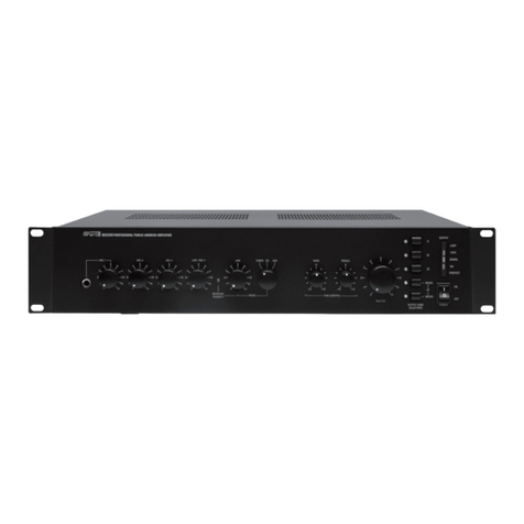
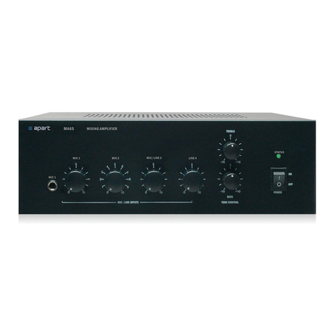
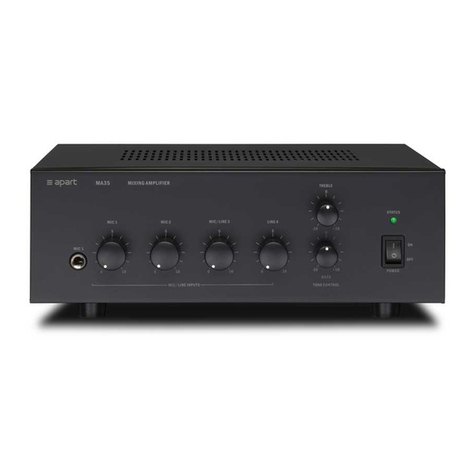
FRONT PANEL
1. Power switch
To turn the power on and off.
2. Power / limit indicator
This led will light green after powering on and working under normal conditions.
When you draw too much power from your MA35, this led will turn red, telling you you're 3 dB under the peak power
and limiting starts.
For the best sound and longest life this led should be kept green, giving you a safe margin.
This device has convection cooling and should operate within his normal level, which is maximum 35 watts. See that
heat can be dispersed in an easy way. Keep +/- 10 cm free space to the MA35's top and sides.
Temperature protect : in case of overheating, the amplifier will switch itself off and reset after cooling down. However,
please check your impedance of the speakerlines which is probably too low (overload !!)
In case of doubt, contact your APart dealer
In case of temp-protect, the indicator will be OFF with the unit switched on.
3. Mic.1 input
This balanced input has been wired in parallel with the XLR and Din5 input at the back.
Use either one of the three inputs for microphone 1. Microphone 1 can be given a priority over all the other inputs by
using the VOX priority (see 21-22).
4. Input 1-2-3-4 volume controls
By turning each control clockwise the desired level of that input in the total mix is set.
To decrease these levels, turn counterclockwise.
The volumes of the inputs not in use, should be set fully counterclockwise. If not, hiss might occur.
5. Treble control
Adjust the level as per your taste or needs. Adding high frequencies gives brilliance to your sound. High frequency
feedback can be removed by decreasing treble.
The centre position gives you a flat response.
REAR PANEL
7. Voltage selector
Set the local voltage. If any doubt, contact your dealer. The unit is shipped with the selector set to 230VAC.
8. Mains socket
The unit can be connected to the mains circuit by a standard IEC type power cord. This socket contains a 1AT, slow blow
fuse. Use a screw driver to flip out the fuse compartment and to replace it by the same type. When this fuse blows
frequently you should bring the MA35 to a qualified service centre. First check whether you didn't use a quick-blow fuse!
9. DC power inlet
The MA35 can be fed from any 12VDC power supply such as your car battery. The voltage can be slightly higher, up to
14VDC.
10. Speaker output (max. 35 watts)
For low impedance use COM and 8 ? . Keep impedance above 8 ? .
For 70 or 100V speaker lines use COM and 70 or 100V terminals. Don't mix the types of speaker connections. Only one at
the time should be used. For 100V operation, the minimum impedance has to be 286 ? . For 70V operation the minimum
impedance should be 140 ? .
11. Mute control terminals
By shorting this terminals the signals coming from inputs 3 and 4 will be muted and the chime will be activated, if the chime
level has been turned on (see 19 ).
12. Ground terminal
By connecting external equipment to your MA35, hum noise might occur. Connecting this terminal to the functional terminal
of the other equipment may reduce this noise. A more common solution to get rid of buzz (ground loops) is to use a
ground-loop isolator in the signal path.
13. Pre amp in / out
You can send the signal of the preamplifier to an external device such as an equalizer (APart PXQ2215) or limiter and feed
the treated signal back into the amplifier via the poweramp input. When you don't use this feature, the RCAbridge should
be placed.
14. Rec out
When you need a copy of the contents you page, you can connect this output to any recording device such as tape decks,
MD recorders, VHS recorders, etc….You can also use this output to feed an extra amplifier. When you connect your MA35
pre amp out or record out to a microphone input of another mixing amplifier, this input will have signal overload and the
sound will be masked. In this case you should use a DI-box or other signal levelling device. Never connect this output to
an amplifier loudspeaker output!
15. Line 4 input
Here you can connect any line level stereo device such as tuners, CD players, MD players, etc….
16. Line 3 / Mic 3 input
Use only one of these parallel wired inputs at the time! For line levels see 15. To the XLR3 balanced input you can connect
any microphone using a balanced, two wire shielded, cable. (1=earth / 2 =hot / 3=cold). For using condenser microphones
see 20.
17. Mic 2 XLR / JACK
Use only one of these parallel wired balanced inputs at the time! See wiring diagram at the back. You can use an
unbalanced microphone on the Jack input. WARNING! When you have activated the phantom power you should NOT
branch any unbalanced jack!
18. Mic 1 XLR / DIN5
Use only one of these parallel wired balanced inputs at the time! See wiring diagram at the back. These two inputs have
been wired in parallel with the balanced jack input at the front. When you use theAPart MICPAT or MICPACB paging
microphones, connected directly to the DIN5 input, the signals fed into input 3 and 4 are muted automatically while paging.
To use VOX MUTE see 21.
19. Chime level
When you use the mute/chime contacts of the DIN5 connector or the mute contacts described in item 11, the level of the
chime can be set with this attenuator. When you turn him completely counterclockwise NO chime shall be heard.
7 8
9 10 11
12 13 14 15 16 17 18 19
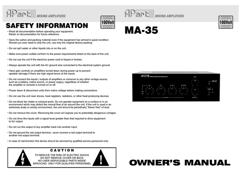
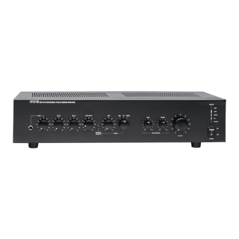
The MA35 is a very compact PAsystem with the features of a real professional.
With its three balanced microphone and two rca line inputs, this little one has a lot of potential.
You even will be able to page from your car.
The MA35 complies with the CE standards.
Before using your MA35, take a few minutes to read these instructions carefully.
This little time can avoid a lot of headaches afterwards.
52
