APEC PUMP ECK-3HP Series Instructions for use

Instruction and Maintenance Manual
ECK-3HP Series

2
Introduction
Thank you for selecting the ECK submersible grinder pump.
This instruction manual explains the product operations and gives important
precautions regarding its safe use. In order to use the product to maximum
benefit, be sure to read the instructions thoroughly and follow them carefully.
To avoid accident, do not use the pump in any way other than as described
in this instruction manual especial on ! WARNING .. After reading this
instruction manual, keep it nearby as a reference in case questions arise
INDEX
Introduction……………….…..PAGE. 2
Prior to Operation………..…..PAGE. 2
Nameplate format…….……...PAGE. 3
Installation…………...…….….PAGE. 3
Electrical Wiring……..…….….PAGE. 4
Operation……………………….….…PAGE. 4
Maintenance………………………….PAGE. 5
Disassembly and Assembly…….…..PAGE. 5
Construction………………………..…PAGE. 6
Troubleshooting………………..…..…PAGE. 8
Prior to Operation
Check the following points upon receipt of your pump:
Is the pump exactly what you ordered? Check nameplate. It is especially important that
you check whether the pump is to be used with 50 or 60 Hz.
Has any damage occurred during shipment? Are any bolts or nuts loose?
Have all necessary accessories been supplied?
(For a list of standard accessories see Construction )
We recommend that you keep a spare pump on hand in case of emergencies. Keep
this instruction manual in a place for future reference.
Item Specifications
Type Sewage, waste water, Storm water drainage
Liquid
handled Temperature 0~40C°(32~104˚F)
Range Output 2.2 kw (3 HP) Three phase
Materials
Volute ASTM A48 Class 30
Impeller ASTM A48 Class 30
Shaft AISI 410 stainless steel
Motor type Dry type submersible motor
Shaft seal lubrication oil Turbine No.32 ISO VG-32

3
Installation
1. Check the following before beginning installation.
Insulation resistance measurement:
With the motor and cable (excluding the power supply cable) immersed in water, use a Megger to
measure the insulation resistance between ground and each phase of the motor, and again between
each phase of the motor. The Megger should indicate an insulation resistance of not less than
20mega ohms. While making the measurement, keep the power supply cable off the ground.
We recommend that an auxiliary pump be kept on hand in case of emergency.
2. Installation-
1.! WARNING : Under no circumstances should cable be pulled while the pump is being transported or
installed.
Attach a chain or rope to the grip and install the pump.
2.This pump must not be installed on its side or operated a dry condition. Ensure that it is installed up-
right on a secure base.
3.Install the pump at a location in the tank where there is the least turbulence.
4. If there is a flow of liquid inside the tank, support the piping where appropriate.
5.Install piping so that air will not be entrapped. If piping must be installed in such a way that air pockets
are unavoidable, install an air release valve wherever such air pockets are most likely to develop.
Nameplate format
6.Do not permit end of discharge piping to be
submerged, as backflow will result when the
pump is shut down.
7..! WARNING : Non-automatic pumps do
not have an automatic operating system. Do
not operate the pump for a long time with the
water level near the lowest water level(H1)
as shown in Fig-1 , as the automatic cut-off
switch incorporated inside the motor will be
activated. Fig-1
H2
H1
off
on
H1: Lowest water level (Motor flange)
H2: Operating water level
This must be above the top of the motor

4
Electrical Wiring
1.Wiring
A) Wire as indicated for the appropriate start system as shown in Fig-2 for three phase in Star
connection.
B) Loose connections will stop the pump. Make sure all electrical connections are secured.
2.Cable
WARNING : Never let the end of the cable contact water.
C) If the cable is extended, do not immerse the splice in water.
D) Fasten the cable to the discharge piping with tape or vinyl strips.
E) Install the cable so that it will not overheat. Overheating caused by coiling the cable and exposing it
to direct sunlight.
3.Grounding
To ground the green wire (label G). Under no circumstances should the green wire be connected to the
power supply.
4. WARNING : Use short circuit breakers to prevent danger of electrical shock.
Fig-2
Operation
1. Before starting the pump
1. After completing installation, measure the insulation resistance again as described in Installa-
tion.
2. Check water level.
If the pump is operated continuously for an extended period of time in a dry condition or at
the lowest water level, the motor protector will be shut off the power. Constant operating in
above condition will shorten pump life time. Do not start the pump again in such a situation
before the motor has completely cooled.
2. Test operation….
Non-automatic pump
(1) Turn the operating switch on and off a couple of times to check switch function.
(2) Next, check direction of rotation. If discharge volume is low or unusual sounds are heard
when the pump is operating, rotation direction is reversed. When this happens, reverse two
of the wires.

5
Maintenance
Check pressure, output, voltage, current and other specifications. Unusual readings may indicate.
Refer to Troubleshooting and correct as soon as possible.
1. Daily inspections
Check current and ammeter fluctuation daily. If ammeter fluctuation is great, even though within
the limits of pump rating, foreign matter may be clogged the pump. If the volume of liquid dis-
charged falls suddenly, foreign matter may be blocked the suction inlet.
2. Regular inspections
Monthly inspections
Measure the insulation resistance. The value should be more than 1M ohm. If resistance starts to
fall rapidly even with an initial indication of over 1M ohm, this may be an indication of trouble and
repair work is required.
Annual inspections
To prolong the service life of the mechanical seal by replacing the oil in the mechanical seal cham-
ber once a year. Water mixed the oil or cloudy textures are indications of a defective mechanical
seal requiring replacement. When replacing the oil, lay the pump on its side with filler plug on top.
Fill suitable amount turbine oil No.32 (ISO VG-32)
Inspections at 3-5year intervals
Conduct an overhaul of the pump. These intervals will help to avoid possible failure in future.
3. Parts need to be replaced
Replace the appropriate part when the following conditions appear.
Note: above replacement schedule is based on normal operating conditions.
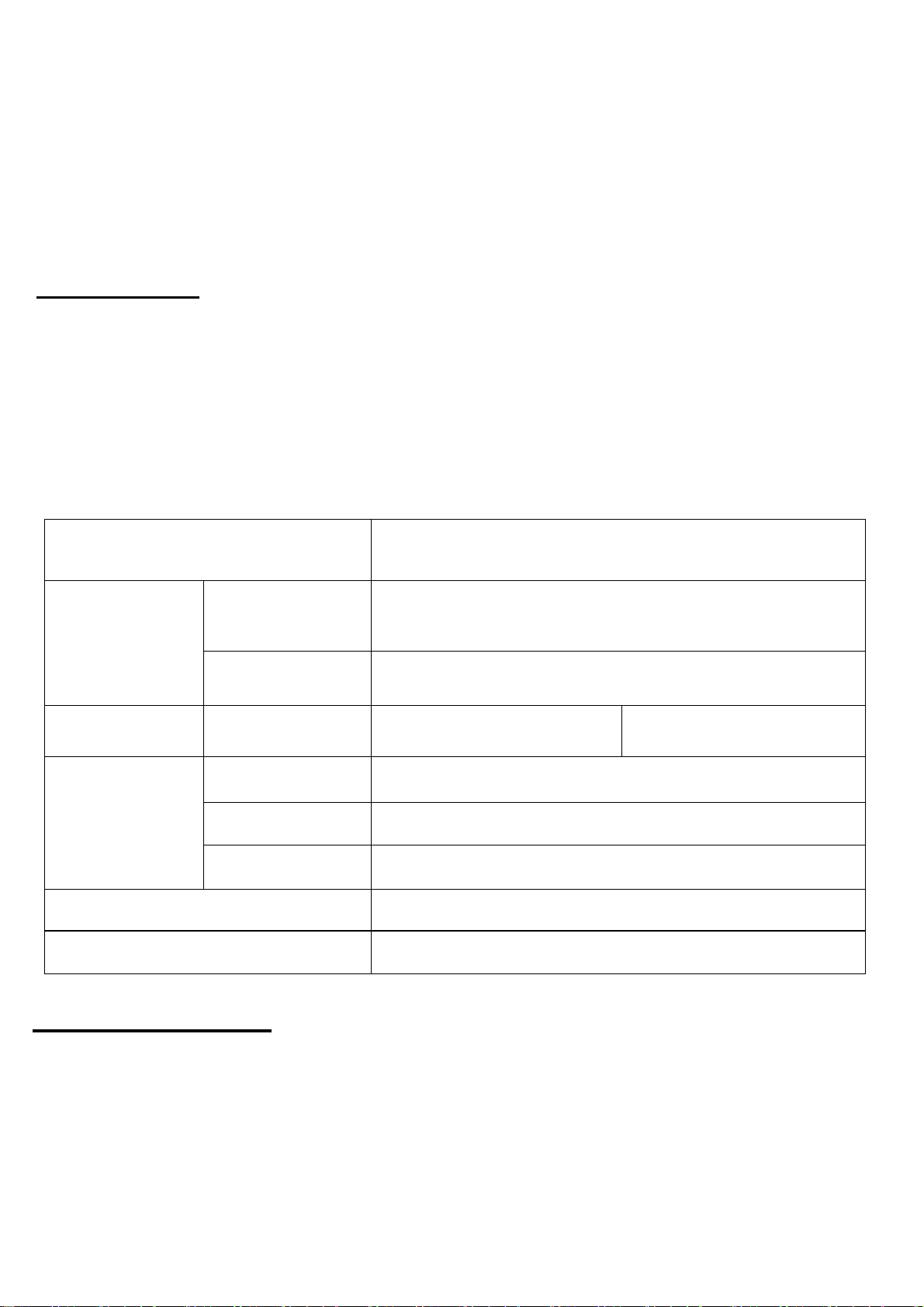
Replaceable part Mechanical seal Oil filler plug gasket Lubricating oil O-ring
Condition Oil in mechanical
seal chamber
Inspect or replace
the oil Oil is clouded or dirty Overhaul the pump
Frequency Annual Half a year Half a year Annual
Disassembly and Assembly
1. Disassembly-
When disassembling pump, have a piece of cardboard or wooden board ready to
place the different parts on as you work. Do not pile parts on top of each other. They
should be laid out neatly in rows. The “O” ring and gasket cannot be used again once
they are removed. Have replacement parts ready. Disassemble in the following order,
referring to the sectional view.
Be sure to cut off power source before disassembly.
(1) Remove pump casing bolts, raise the motor section and remove pump casing.
(2) Remove shaft head bolt and impeller.
(3) Remove oil filler plug and drain lubricating oil.
(4) Remove intermediate casing bolts and oil chamber.
(Remember that any lubricating oil remaining in the mechanical seal chamber will flow out.)
(5)Carefully remove mechanical seal, beware of not to scratch sliding surface of
motor shaft.
2. Assembly-
Re-assemble in reverse order of disassembly.
Be careful of the following points.
(A) During re-assembly, rotate the impeller by hand and check for smooth rotation. If
rotation is not smooth, perform steps-(3) through -(5) again.
(B) Upon completion of re-assembly step -(1) rotate the impeller by hand from the
suction inlet and check that it rotates smoothly without touching the suction
cover before operating the pump.
Please order “O” rings, packing, shaft seals and other parts from your dealer.

6
Construction
ECK 3HP

7
NO Name Mtrl
1 Cable H07RN-F / STOW
2 Motor Cover EN-GJL-200
3 Motor Housing EN-GJL-200
4 Oil Chamber EN-GJL-200
5 Volute EN-GJL-200
6 Impeller EN-GJL-200
7 Suction Plate EN-GJS-700
8 Pump Feet SC
9 Discharge Elbow EN-GJL-200
10 Flange EN-GJL-200
11 Mechanical Seal Top: CA/CE
Bottom: SIC/SIC
12 Oil Seal NBR
13-1 Upper Bearing NTN 6304
13-2 Lower Bearing NTN 6307
14 Stator
15 Rotor with Shaft SUS 410
16 O-Ring NBR
17 O-Ring NBR
18 Flange Gasket NBR
19 Elbow Gasket NBR
20 Suction Plate Gasket PE
21 Overload Protector
22 Air Release Valve PP
23 Hex. Screw SUS 304
24 Eye Bolt SUS 304
25 Socket Screw& O-Ring SUS 304/NBR
26 Hex. Screw & Spring Washer SUS 304
27 Hex. Screw & Spring Washer SUS 304
28 Spring Washer SUS 304
29 Nut SUS 304
30 Key SUS 304
31 Hex. Screw & Washer SC
32 Hex. Screw and Spring Washer SUS 304
33 Socket Screw & O-Ring SUS 304/NBR
34 Phillips Screw SC
35 Hex Screw & Spring Washer SUS 304
36 Hex Screw & Spring Washer SUS 304
37 Hex Screw & Spring Washer SUS 304
38 Hex Screw SC
39 Wave Washer SC
40 Insulation Sheet PAPER
41 Ground lead

8
Troubleshooting
Trouble Cause Remedy
Does not start.
Starts, but imme-
diately stops.
(1) Power failure (1)~(3) Contact electric power company and
devise counter-measures
(2) Large discrepancy between power source and voltage
(3) Significant drop in voltage
(4) Motor phase malfunction (4) Inspect electric circuit
(5) Electric circuit connection faulty (5) Correct wiring
(6) Faulty connection of control circuit (6) Inspect connections and magnetic coil
(7) Fuses is blown (7) Check circuit then replace fuse
(8) Faulty magnetic switch (8) Replace with correct one
(9) Water is not at level indicated by Float (9) Raise water level
(10) Float is not in appropriate level (10) Adjust the position of float
(11) Float is not effective (11) Repair or replace
(12) Short circuit breaker is functioning (12) Repair location of short circuit
(13) Foreign matter clogging pump (13) Remove foreign matter
(14) Motor burned out (14) Repair or replace
(15) Motor bearing broken (15) Repair or replace
Operates, but
stops after a
while.
(1) Prolonged dry operation has activated motor protector
and caused pump to stop
(1) Raise water level to C.W.L
(2) High liquid temperature has activated motor protector
and caused pump to stop
(2) Lower liquid temperature
(3) Reverse rotation ! WARNING : (3) Correct rotation
Does not pump.
Inadequate vol-
ume.
(1) Reverse rotation (1) Correct rotation (see Operation)
(2) Significant drop in voltage (2) Contact electric power company
(3) Operating a 60Hz pump with 50Hz (3) Check nameplate
(4) Discharge head is high (4) Recalculate and adjust
(5) Large piping loss (5) Recalculate and adjust
(6) Low operating water level causes air suction (6) Raise water level or lower pump
(7) Leaking from discharge piping (7) Inspect, repair
(8) Clogging of discharge piping (8) Remove foreign matter
(9) Foreign matter in suction inlet (9) Remove foreign matter
(10) Foreign matter clogging pump (10) Remove foreign matter
(11) Worn impeller (11) Replace impeller
Over current (1) Unbalanced current and voltage (1) Contact electric power company
(2) Significant voltage drop (2) Contact electric power company and
devise counter-measure
(3) Motor phase malfunction (3) Inspect connections and magnetic
switch
(4) Operating 50Hz pump on 60Hz (4) Check nameplate
(5) Reverse rotation ! WARNING : (5) Correct rotation (see Operation)
(6) Low head. Excessive volume of water (6) Replace pump with high head pump
(7) Foreign matter clogging pump (7) Remove foreign matter
(8) Motor bearing is worn out or damaged (8) Replace bearing
Pump vibrates;
excessive oper-
ating noise.
(1) Reverse rotation (1) Correct rotation
(2) Pump clogged with foreign matter
(2) Disassemble and remove foreign matter
(3) Piping resonates (3) Improve piping
(4) Strainer is closed too far (4) Open strainer
Vol.PMECK3HP-19101
Table of contents
Other APEC PUMP Water Pump manuals