4
Installation
1. Check the following before beginning installation.
Insulation resistance measurement:
With the motor and cable (excluding the power supply cable) immersed in water, use a Megger to measure the insulation
resistance between ground and each phase of the motor, and again between each phase of the motor. The Megger should
indicate an insulation resistance of not less than 20mega ohms. While making the measurement, keep the power supply ca-
ble off the ground.
We recommend that an auxiliary pump be kept on hand in case of emergency.
2. Installation
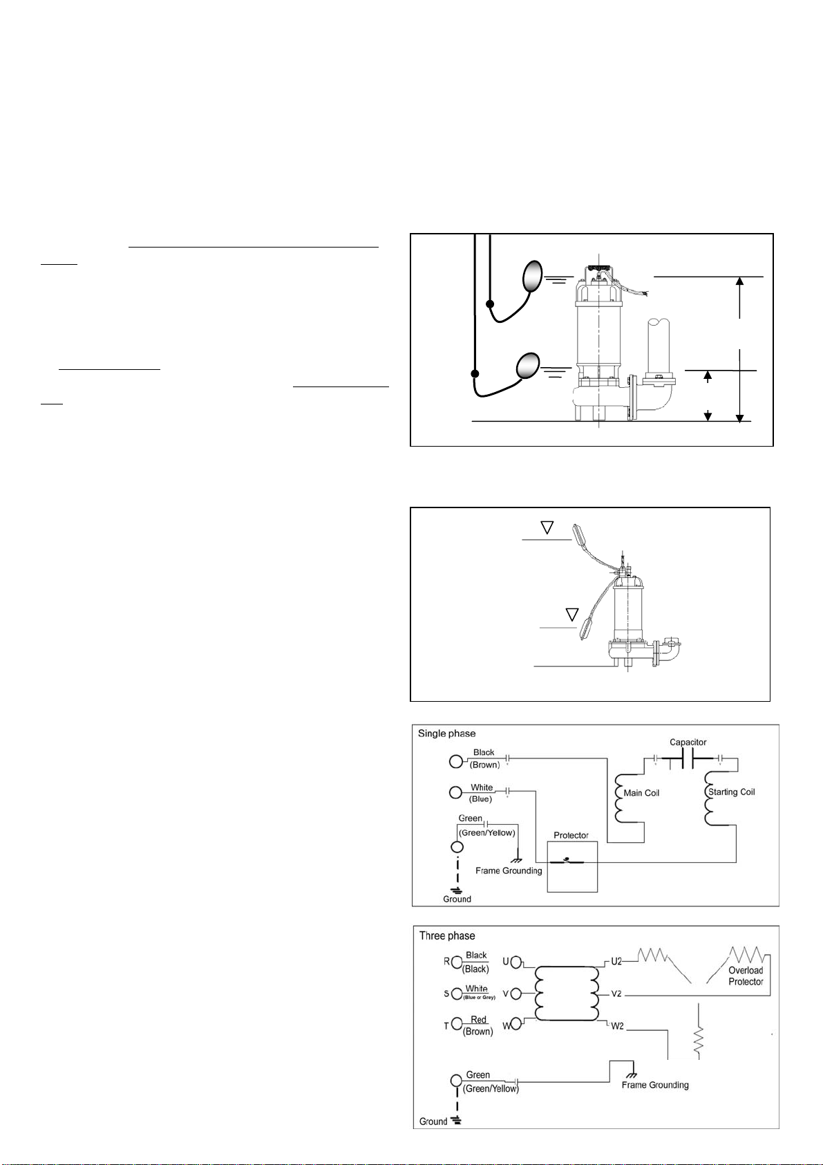
Fig-1
H2
H1
off
on
Fig-2
Operating Water Level
Stop Water Level
H1: Lowest water level (Motor flange)
H2: Operating water level
This must be above the top of the motor
1.! WARNING : Under no circumstances should cable be
pulled while the pump is being transported or installed.
Attach a chain or rope to the grip and install the pump.
2.This pump must not be installed on its side or operated a
dry condition. Ensure that it is installed upright on a se-
cure base.
3.Install the pump at a location in the tank where there is
the least turbulence.
4. If there is a flow of liquid inside the tank, support the pip-
ing where appropriate.
5.Install piping so that air will not be entrapped. If piping
must be installed in such a way that air pockets are un-
avoidable, install an air release valve wherever such air
pockets are most likely to develop.
6.Do not permit end of discharge piping to be submerged,
as backflow will result when the pump is shut down.
7..! WARNING : Non-automatic pumps do not have an
automatic operating system. Do not operate the pump for
a long time with the water level near the lowest water
level(H1) as shown in Fig.1, as the automatic cut-off
switch incorporated inside the motor will be activated.
8.To avoid dry operation, install an automatic operating sys-
tem so that this will not happen, as shown in Fig.2 and
maintain a safe operating water level.
Electrical wiring
1.Wiring
A. Wire as indicated for the appropriate start system as
shown in Fig-3.
B. Loose connections will stop the pump. Make sure all
electrical connections secure.
2. Cable
C. ! WARNING : Never let the end of the cable con-
tact water.
D. If the cable is extended, do not immerse the splice
in water.
E. Fasten the cable to the discharge piping with tape or
vinyl strips.
F. Install the cable so that it will not overheat. Over-
heating caused by coiling the cable and exposing it
to direct sunlight.
3. Grounding
As shown in Fig-4 ground the green wire (label E).
Under no circumstances should the green wire be
connected to the power supply.
4. ! WARNING : Use short circuit breakers to prevent
danger of electrical shock.
Fig-3
Fig-4