Appalachian Stove & Fabricators XLB Installation guide

GEMINI-XLB
ZERO-CLEARANCE
By Appalachian
INSTALLATION
AND OPERATION
PROCEDURES
FIREPLACE INSERT - FREESTANDING
SAFETY NOTE
If this stove is not properly installed a house fire may result. For your safety, follow the installation
directions. Contact local building or fire officials about restrictions and installation inspection
requirements in your area.
This stove must be connected to a listed high temperature residential type and building heating
appliance chimney or an approved masonry chimney with flue liner.
GEMINI PATENT
PAT.#4,607,611
August 26th, 1986
© 1994 Appalachian Stove & Fabricators, Inc.

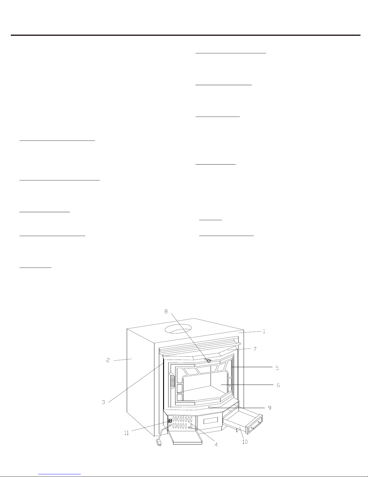
I. Stove Features and Operating Controls....................3
II. Clearances for Installation.......................................4
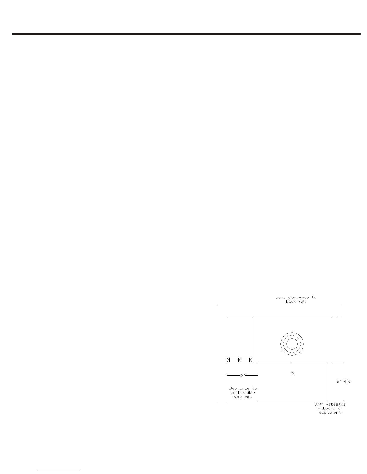
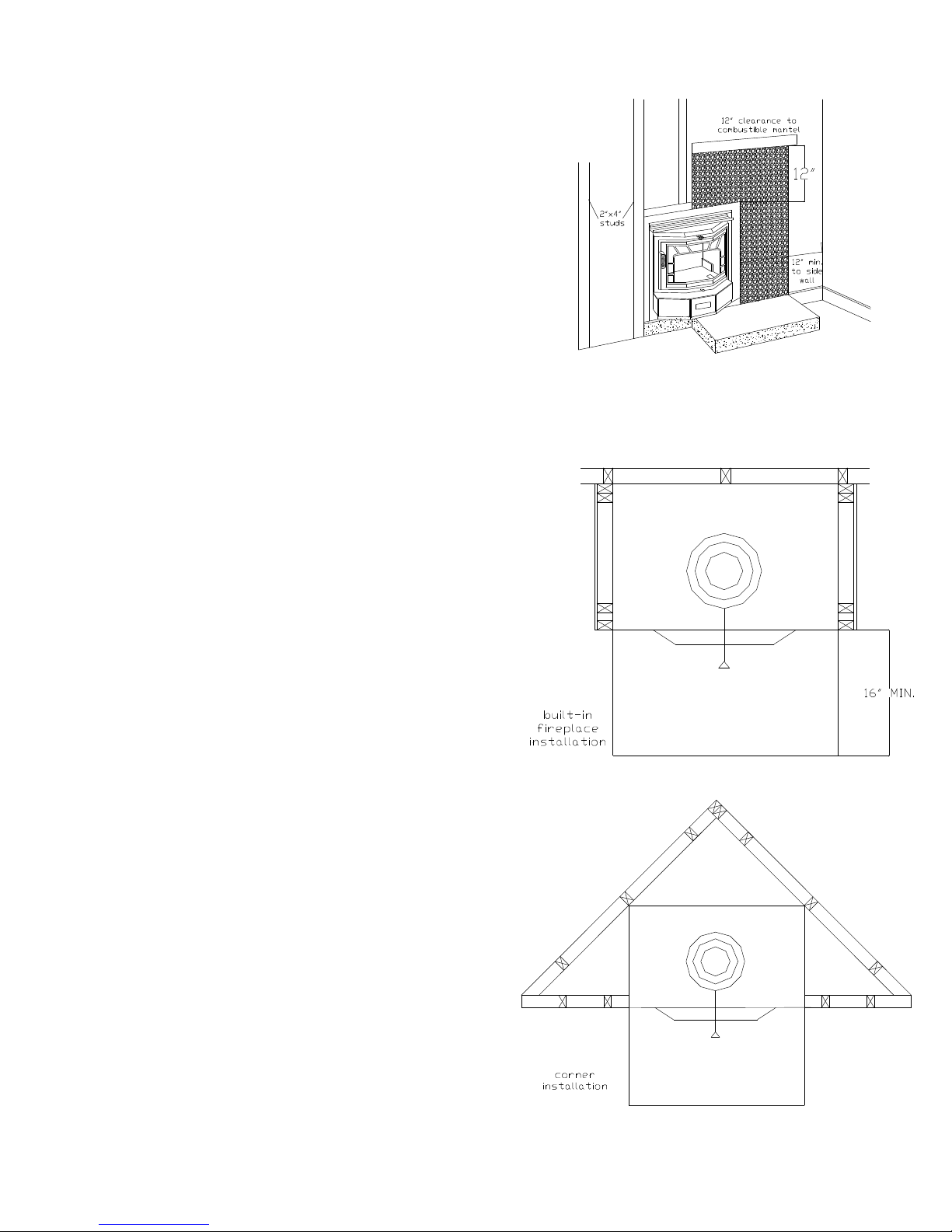
1. Clearances for Fireplace Installation.....................4
2. Clearances for Freestanding Installation...............4
III. Installation as a Fireplace Unit...............................5
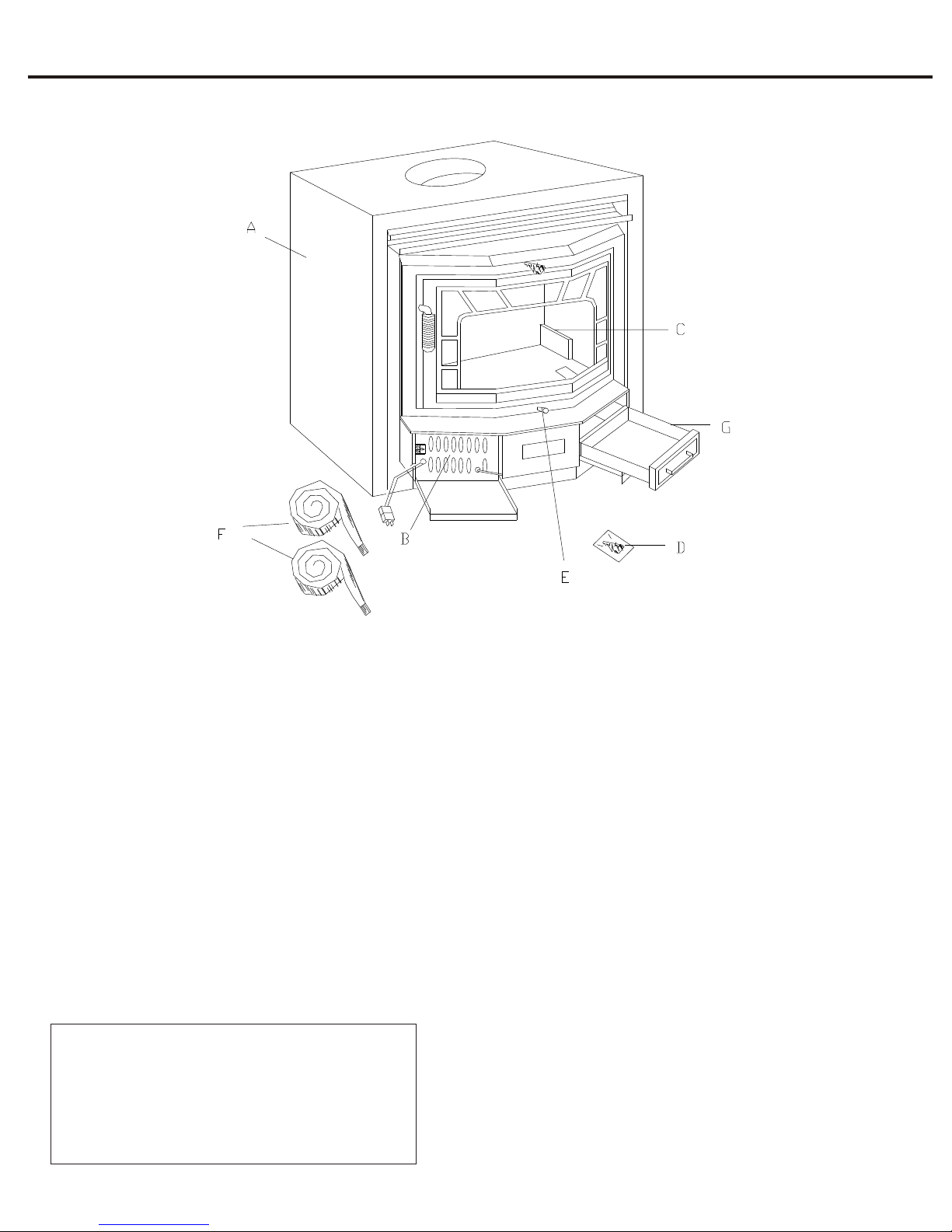
1. Stove Components...............................................5
2. Mounting the Optional Trim Panels......................5
3. Installing the Gemini XLB Unit............................6
4. Importance of Proper Draft..................................6
IV. Freestanding Installation.........................................7
1. Stove Components...............................................7
2. Preparation...........................................................7
3. Attaching the Freestanding Kit..............................8
4. Importance of Proper Draft..................................8
5. Mounting the Stove Pipe......................................8
6. Chimney Installation............................................9
V. Installing the Brass Trim........................................10
1. Standard Brass....................................................10
2. Optional Brass....................................................10
VI. Catalytic Combusters...........................................11
1. General Information...........................................11
(A) Tamper Warning...........................................11
(B) Manufacturer and Warranty Info..................11
2. Catalyst Monitoring...........................................11
3. Catalyst Troubleshooting General Info...............12
4. Catalyst Replacement.........................................13
VII. Stove Operation.................................................14
1. Fuel Selection.....................................................14
2. Building and Maintaining a Fire.........................14
3. Refueling the Stove.............................................14
4. Achieving Catalyst Light-Off
From a Cold Start..........................................14
5. Catalyst Light-Off When Refueling....................14
VIII. Maintenance.....................................................15
1. Ash Removal......................................................15
2. Care of the Glass................................................15
3. Chimney Care....................................................15
4. Stove Finish........................................................15
5. Blower Care.......................................................15
6. Door Gasket Replacement..................................15
7. Motor Maintenance...........................................15
TABLE OF CONTENTS
IX. Safety......................................................................16
X. Limited Warranty....................................................16
XI. Warranty Registration.............................................17
NOTE: Tested and listed by Arnold Greene Testing
Laboratories to test standards ANSI-UL 1482, 737, 127
HUD specifications and Uniform Building Code.
Thank you for purchasing the Gemini XLB stove.
Appalachian Stove welcomes you to the growing ranks of
energy conscious Americans.
Heating with wood and bituminous coal is one way to
conserve resources and to stimulate a healthy economy.
The forest industry has worked for many years to assure a
continual supply of our most abundant renewable
resource - wood.
To fully benefit from your stove and to ensure safe
operation, follow the instructions in this manual carefully.
We hope you enjoy many years of safe, economical heat
from your Gemini XLB stove.
This manual describes the installation and operation of
the Appalachian Stove’s Gemini XLB catalytic equipped
wood heater. This heater meets the United States
Environmental Protection Agency’s emission limit for
wood heaters sold after July 1, 1988. Under specific
conditions, this heater has been shown to deliver heat at
rates ranging from 10,100 to 26,900 BTU/hour.
2

I. FEATURES AND OPERATING CONTROLS
3
Before installing and operating the Gemini XLB Zero
Clearance unit, familiarize yourself with its features and
operating controls. The Gemini XLB is designed for use
with zero-clearance to combustibles. Care should be taken
when selecting a stove site. A centrally located site is
preferable, if possible, to ensure more equal heating
distribution throughout your home. If you plan to install
the Gemini XLB as a fireplace unit, the site you select for
installation and finishing construction will enhance your
present decor and heat your home more efficiently.
1. Quality Steel Construction - assures you of years of
dependable service. The firebox is constructed of 4 gauge
plated steel that is completely welded for safe, durable
installation.
2. Special Fireproof Insulation - lines the solid steel outer
box and covers the firebox to provide high temperature
resistance.
3. Warm Air Outlets - distribute the heated air from around
the firebox.
4. Front Mounted Blower - circulates air around the fire
chamber for increased heat extraction. Easy mounting
allows for quick access if service is needed.
5. Glass Door - seals the firebox for high efficiency and
allows you to see the fire.
6. Refractory Firebox Liner - boosts burning efficiency by
reflecting radiant heat back into the fire. This results in a
more thorough and cleaner burn.
7. Warm Air Deflector - on the top stove edge directs the
heated air downward and across the floor for maximum
comfort.
8. Sliding Damper - helps increase heat extraction by
controlling the escape of hot combustion gasses and smoke.
The damper is opened by pulling the control handle out
and closed by pushing the handle in. It may be left in any
intermediate position.
9. Draft controls - regulate the burning rate and the heat
output of the stove. The larger the fire, the more heat the
unit will produce. The drafts are opened by pulling the
controls outward and may be left in any intermediate
position. Start up air (centered under the door) may only be
opened during the building of the fire (5 minute max.).
10. Ash pan - for easy removal of ash.
11. Three speed switch - assists in the adjustment of air
circulation around the firebox. The automatic position is
thermostatically controlled, the blower comes on when the
activation temperature is reached. The manual position
allows for blower start up at any time.

4
1. CLEARANCES FOR FIREPLACE INSTALLATION
To ensure a safe installation, the following minimum
clearances must be met:
(A) Chimney clearance: 6” or 8” insulated class A pipe (low
heat residential type all-fuel) must be used. Follow the pipe
manufacturer’s recommendations.
(B) A minimum of 12” must be maintained from the front
edge of the unit to any wall.
(C) A minimum of 12” must be maintained from the top of
the unit to any combustible overhanging mantel.
(D) A minimum of 16” floor protection in front of the
stove of 3/4” fireproof millboard, or the equivalent, must
be used.
(E) Clearances are affected by the composition of the wall
structure (combustible or non-combustible materials). Use
of non-combustible materials will reduce the clearance
needed.
NOTE: Walls of wood frame construction covered with a
non-combustible veneer, such as brick, are considered
combustible walls.
NOTE: For details on chimney installation, see “Chimney
Installation,” Section IV, No. 5.
2. CLEARANCES FOR FREESTANDING INSTALLATION
The Gemini XLB is specially designed for zero clearance to
combustibles as a freestanding unit (FIGURE 2). Rear and
side-wall clearances depend on two factors:
(A) Composition of the wall structure (combustible or non-
combustible materials). Use of non-combustible materials
will reduce the clearance needed.
(B) Chimney Clearance: 6” or 8” insulated class A pipe
(low residential heat type all-fuel) must be used. Follow
pipe manufacturer’s recommendations.
NOTE: Walls of wood frame construction covered with a
non-combustible veneer, such as brick, are considered
combustible walls.
If the stove is installed on a combustible floor, a protective
pad of 3/4” fireproof millboard, or equivalent, must extend
16” in front of the stove unit only.
II. CLEARANCES FOR INSTALLATION
FIGURE 2 - FREESTANDING CLEARANCES
(Top View)
SAFETY NOTICE
If this stove is not properly installed a house fire may
result. For your safety, follow the installation directions.
Contact local building or fire officials about restrictions
and installation inspection requirements in your area.
This stove must be connected to a listed high
temperature residential type and building heating
appliance chimney or an approved masonry chimney
with flue liner.
FRAMING DIMENSIONS
41.25” WIDE
25” DEEP
37” HIGH

5
III. INSTALLATION AS A FIREPLACE UNIT
FIGURE 4
TRIM PANELS (OPTIONAL)
FIGURE 3
FIREPLACE UNIT STOVE COMPONENTS
1. STOVE COMPONENTS
The following components are included with the
Gemini XLB unit:
(A) Gemini XLB Unit
(B) Blower Assembly
(C) Refractory Firebox Liner
(D) Damper Spring
(E) Draft Contol Knob
(F) Heat Resistant Insulation Rolls
(G) Ash Pan
2. Mounting Optional Trim Panels
(A) Mount the top trim panel with the mounting screws
provided.
(B) Mount side panels.
NOTE: The Gemini XLB trim kit may be installed ½”
to a maximum of 2-1/2” from the front edge of the
stove. One half inch is preferred.

6
3. INSTALLING THE GEMINI XLB UNIT (Fireplace
Installation)
Special care should be taken in selecting the site for fireplace
installation of the Gemini XLB unit. A centrally located site
will provide equal heat distribution. The site you select for
installation, and the unfinished construction, will also
enhance the value and overall appearance of your home.
Finishing construction details may be done in wood, brick,
paneling, “cut” or “natural” stone masonry to blend with
your present decor.
(A) After selecting your site, place the Gemini XLB unit in
the desired position.
(B) Attach the chimney to the stove by following the special
instructions on page 8 in the freestanding section.
(C) Finish construction around the unit (FIGURE 5).
(D) Trim the stove unit in desired materials to match your
decor (wood, paneling, brick, “cut” or “natural” stone may
be used).
(E) Install the protective hearth in front of the unit last, after
all other construction is complete.
(F) Do not block any natural cooling vents of the Gemini
XLB fireplace unit when installing.
NOTE: If a raised hearth is used, raise the Gemini XLB unit
in proportion to the elevation to avoid blocking stove vents
and to maintain correct 22” hearth clearance to combustibles.
This completes the installation of your Gemini XLB unit.
Please refer to section VII and VIII for instruction on
operation and stove maintenance.
4. IMPORTANCE OF PROPER DRAFT
Draft is the force which moves air from the appliance up
through the chimney. The amount of draft in your chimney
depends on the length of the chimney, local geography,
nearby obstructions and other factors. Too much draft may
lead to excessive temperatures in the appliance and may
damage the catalytic combustors. Inadequate draft may cause
backpuffing into the room and “plugging” of the chimney
catalyst.
NOTE: Inadequate draft will cause the appliance to leak
smoke into the room through the appliance and chimney
connector joints.
NOTE: An uncontrollable burn or a glowing red stove part
or chimney connector indicates excessive draft.
FIGURE 6
INSTALLATION SUGGESTIONS
(Top View)
FIGURE 5
FINISHING THE CONSTRUCTION
FOR FIREPLACE INSULATION

7
IV. FREESTANDING INSTALLATION
FIGURE 7
FREESTANDING STOVE COMPONENTS
1. STOVE COMPONENTS
The following components are included with
the Gemini XLB stove freestanding model:
(A) Gemini XLB Unit
(B) Blower Assembly
(C) Refractory Firebox Liner
(D) Damper Spring
(E) Draft Control Knob
(F) Heat Resistant Insulation Rolls
(G) Ash Pan
(H) Pedestal (Optional) (Not Shown)
2. PREPARATION
Proper preparation and planning of the installation will simplify
the job and help achieve effective operation of the unit.
(A) Select the location for the stove installation. The stove should
be positioned so that the air flows to the rest of the home in the
most direct route possible.
(B) Locate the approximate penetration point of the chimney
structure. Avoid roof areas such as valleys, ridges, dormers and
hips.
If the installation is being made on a combustible floor, place the
floor protector in position. (Section II.)
If you are using the optional freestanding base, attach it at this
time.
Place the stove in position. Check clearances. (Section II).
PREVENT CREOSOTE FIRE; INSPECT CHIMNEY
CONNECTOR AND CHIMNEY TWICE MONTHLY AND
CLEAN IF NECESSARY.
DO NOT OVERFIRE; IF UNIT OR CHIMNEY CONNECTION
GLOWS, YOU ARE OVERHEATING.
KEEP FURNISHINGS AND OTHER COMBUSTIBLE
MATERIALS A CONSIDERABLE DISTANCE AWAY FROM
APPLIANCES.
TYPE OF FUEL: WOOD ONLY
FIGURE 7-B
FREESTANDING CAUTION TAG

8
3. ATTACHING THE FREESTANDING KIT
Tool needed: Drill
(A) Remove the wooden blocks from the bottom of the
stove.
(B) Position the pedestal on the bottom of the stove so that
it is centered from the sides, sits inside the angle, and is
even with the angle at the front of the stove. The “turned
in” flanges on the pedestal should be placed against the
bottom of the stove. (NOTE: The vent opening on the
bottom of the stove should be completely inside the
pedestal.)
(C) Attach the pedestal using the drill screws provided.
Drill into the holes after the pedestal is positioned correctly.
The screws will make their own hole in the stove bottom.
4. IMPORTANCE OF PROPER DRAFT
Draft is the force that moves air from the appliance up
through the chimney. The amount of draft in your chimney
depends on the length of the chimney, local geography,
nearby obstructions, and other factors. Too much draft may
lead to excessive temperatures in the appliance and may
damage the catalytic combustors. Inadequate draft may
cause backpuffing into the room and “plugging” of the
chimney catalyst.
NOTE: Inadequate draft will cause the appliance to leak
smoke into the room through the appliance and chimney
connector joints.
NOTE: An uncontrollable burn or a glowing red stove part
or chimney connector indicates excessive draft.
5. MOUNTING THE STOVE PIPE
(A) Pipe may be 6” or 8” insulated class A.
(B) Slide and secure the pipe onto drip-proof connector
mounted in the Gemini XLB unit.
(C) Fill the air space between the pipe and the Gemini XLB
unit with heat resistant insulation.
FIGURE 8A
FIGURE 8B
FIGURE 9
MOUNTING THE STOVE PIPE

9
6. CHIMNEY INSTALLATION
(A) Chimney clearance: 6”or 8” insulated class A pipe
(low heat residential all fuel) must be used. Follow pipe
manufacturer’s recommendations.
CAUTION: If, for any reason, you decide to use
chimney pipe other than class A pipe, consult your fire
marshal for safe installation instructions.
Use one layer of insulation for double wall pipe and two
layers for triple wall pipe.
(B) Attaching chimney to Gemini XLB unit (FIGURE 9).
A solid fuel chimney must make a positive connection to
the drip proof pipe connector at all points along base of
pipe connector for proper installation. FIGURE 10
CHIMNEY INSTALLATION

10
V. INSTALLING THE BRASS TRIM
1. STANDARD BRASS
(A) Spring damper handle - screw the handle onto the
damper rod counter-clockwise.
(B) The draft knob is screwed directly into the hole in the
draft side plate.
(C) Installed for your convenience at the factory is the
door handle spring.
2. OPTIONAL BRASS
(A) Brass for front edge of stove:
This brass is installed around the outside edge of the
stove unit. It may be used with both freestanding and
fireplace units. If used in combination with the optional
trim panels for fireplace units, attach the trim panels first.
1. Mount top and side strips to trim panels with self
tapping brass screws provided. Leave approximately 1” at
top edges of trim to be covered by corner brass. If needed,
strips can easily be cut with a hacksaw.
2. Mount two brass corners overlapping top and side
brass strips.
3. Remove protective coating from brass strips before use.
FIGURE 11
FIGURE 13
FRONT EDGE BRASS
FIGURE 12
DRAFT KNOB

1. GENERAL INFORMATION
(A) TAMPER WARNING
This wood heater contains a catalytic combustor, which
needs periodic inspection and replacement for proper
operation. It is against the law to operate this wood
heater in a manner inconsistent with the operating
instructions in this manual, or if the catalytic element is
deactivated or removed.
(B) MANUFACTURER AND WARRANTY INFO
The combustors supplied with this heater are Applied
Ceramics Versagrid Catalytic Converter. Consult the
catalytic combustor warranty also supplied with this
heater.
Warranty claims should be addressed to:
Applied Ceramics - Warranty Department
P.O. Box 29664
Atlanta, GA 30359
(404) 448-6888
Warranty Claims MUST have the following items:
1. Warranty Claim Form
2. Dated Proof of Purchase
3. Check for proper amount (including postage and
handling)
4. APPLIED CERAMICS Catalytic Combustor
2. CATALYST MONITORING
It is important to periodically monitor the operation of
the catalytic combustor to ensure that it is functioning
properly and to determine when it needs to be replaced.
A non-functioning combustor will result in a loss of
heating efficiency and an increase in creosote and
emissions.
Check these items on a periodic basis:
* Visually inspect the combustors at least three times
during the heating season to determine if physical
degradation has occurred. Actual removal of the
combustor is not recommended unless a more detailed
inspection is warranted because of a decrease in
performance. If any of these conditions exist, refer to
the Catalyst Troubleshooting Guide (next page).
VI. CATALYTIC COMBUSTORS
* This catalystic heater may be equipped with a
temperature probe to monitor catalyst operation. Proper
functioning combustors typically maintain temperatures
in excess of 500 degrees F and often reach temperatures
in excess of 1000 degrees F. If catalytic temperatures are
not in excess of 500 degrees, refer to the Catalyst
Troubleshooting Guide or further information located in
this manual.
* To determine if the catalyst is working, compare the
amount of smoke leaving the chimney when the smoke
is going through the combustor and catalyst light-off has
been achieved to the amount of smoke leaving the
chimney when the smoke is not routed through the
combustor (bypass mode - damper open).
1. Light the stove in accordance with instructions given
on how to achieve catalyst light off.
2. With smoke routed through the catalyst, go outside
and observe the emissions from the chimney.
3. Engage the bypass mechanism (open the damper) and
again observe the emissions leaving the chimney.
Significantly more smoke should be seen when the
exhaust is not routed through the combustor (bypass
mode - damper open). Be careful not to confuse smoke
with steam from wet wood.
The Gemini XLB was designed to allow the owner to
monitor the catalyst temperatures. A small port is
located on the top of the stove, inside the unit. From
that port, wires may be led out of the unit to a
temperature monitoring device. Some Gemini models
have this wiring already done. The port is positioned to
allow for temperatures to be taken approximately 1”
behind the right catalyst. The thermocouple and
monitor should be compatible and should read
temperatures to approximately 1800 degrees F.
11
Front Mounted Catalytic Probe
Locate screw above the door and to the left of the
damper. Remove the screw and insert catalytic probe.

12
3. CATALYST TROUBLESHOOTING
The operation of any wood stove can create problems.
While the use of a catalyst equipped wood stove will
substantially lessen some of these problems, such as
creosote formation, other traditional wood stove
problems may remain. These problems are invariable
related to such conditions as draft, aging or failure of
stove components, flue installation, wood supply and
others.
Here are a few clues that may be of some assistance in
discerning problems:
A sluggish stove performance may be attributed to: a
poor chimney draft; an obstruction in the chimney; the
chimney damper being closed; closing the bypass
damper too soon; burning wet or unseasoned wood; the
combustor being plugged or obstructed, or a
combination of the above.
A drop in overall fuel efficiency may be attributed to:
having cold, windy weather; burning wet, pithy or
spongy wood; the combustor not in operational mode
(200-300 plus degrees); or the combustor being broken
or dislodged.
A high fuel consumption may be attributed to: burning
the wrong type of wood for the desired heat output;
improper regulation of draft or inlet air (close damper
after proper light off, install barometric damper set to
.06 inches of water, or close inlet air as much as
possible); cold, windy weather; or the combustor not
engaged or functioning properly.
Backpuffing may be attibuted to: gusts of wind; a hot
combustor (above 1400 degrees F); or opening doors in
a tightly constructed house.
Smoke rollout when the door is opened may be
attributed to: the manual flue being closed; wind gusts
blowing down the chimney; the combustor not at
operational temperature, or the stove door being opened
too quickly.
Glowing stove parts may be attributed to: running the
stove too hot (excessive amounts of wood); a high draft
(reduce when temperatures become too excessive); a
glowing combustor (this is normal during first 1/3 of
burn cycle), or a chimney fire (close inlet air and outlet
dampers completely - if this does not help, vacate home
and call the fire department immediately).
Creosote accumulation may be caused by one or more of
the following: a poorly insulated chimney; a non-
functioning combustor; types and amounts of wood
burned, or a leaking damper plate.
Creosote leakage from metal flue joints may be caused
by one or more of the following: no chimney cap; metal
flue assembled improperly, or a normal increase in the
moisture due to a higher efficiency of catalytic burning
(condensation on cool chimney walls).
A heavy concentration of smoke leaving the chimney
may be attributed to one or more of the following:
improper wood being burned; the damper being open,
or water vapor (on cold, still days, water vapor is often
mistaken for smoke. Water vapor appears to be white
and tends to rise vertically and dissipate rapidly while
smoke is usually bluish brown and drifts down and
settles in low areas before dissipating).
A poor draft may be attributed to these factors: an
improper chimney height; wrong size flue being used;
cooler temperatures caused by external chimney, or a
massive stone or masonry chimney.
An unhealthy combustor can be attributed to plugging,
catalyst peeling, catalyst deactivation, masking, substrate
cracking (thermal and mechanical), substrate crumbling,
color variations (does not affect performance), or
catalyst abrasion. An excellent guide to pinpointing and
correcting these problems can be found by consulting
the catalyst warranty.

13
4. CATALYST REPLACEMENT
To replace damaged or non-functioning catalytics follow these steps:
A) Loosen the damper tab bolts with 9/16” socket to allow the damper tab to slide back. Lower the cast housing as
shown.
B) Remove the mixing plate, sealing plate and catalyst. Clean the area where the catalyst sits to remove old gasketing.
Inside the stove, check the area where the damper system was located and clean away old gasketing, if necessary.
C) Install the new catalysts. Uncanned catalysts (catalysts not in metal housing) should be wrapped with 1/16”
gasketing before installing. Locate the catalysts ½” from the front of the damper housing. Re-install the sealing.
D) New gasketing should be installed to allow for a seal between the damper housing and the firebox top. This may
be done by putting a layer of gasketing around the top where the housing is located. In both cases, the use of an
adhesive to hold the gasketing in place will make the installation easier.
E) Remount the cast housing in the back of the stove. Tighten damper tab bolts. Make sure the damper slides easily.
Use furnace cement to seal gaps between the sealing plate and the catalysts, the rod guide and the top of the firebox.

Proper operation of your Gemini XLB Zero Clearance
unit will help to ensure safe, efficient heating. Please
take a few moments to review these simple operating
instructions.
1. FUEL SELECTION
The Gemini XLB is designed to burn natural wood only.
Higher efficiencies and lower emissions generally result
when burning air dried seasoned hardwoods, as
compared to softwoods or to green or freshly cut
hardwoods. DO NOT BURN THE FOLLOWING:
treated wood, coal, garbage, solvents, colored papers, or
trash. Burning these may result in the release of toxic
fumes and may poison or render the catalytic ineffective.
Burning coal, cardboard, or loose paper can produce
soot, or large flakes of char or fly ash that can coat the
combustor, causing smoke spillage into the room,
rendering the combustor ineffective.
2. BUILDING AND MAINTAINING A FIRE
(A) Open the damper fully by pulling the damper
control panel all the way out.
(B) Place a base of crumpled uncolored newspaper in the
bottom of the stove. Lay pieces of kindling on top of the
newspaper and light it.
(C) As the kindling begins to burn, add several larger
pieces of wood until the fire is burning well. At this
point, regular size logs may be added.
NOTE: Until the fire is burning well, leave the draft
controls in the door fully open.
NEVER USE GASOLINE, GASOLINE TYPE
LANTERN FUEL, KEROSENE, CHARCOAL,
LIGHTER FLUID, OR SIMILAR LIQUIDS TO START
OR “FRESHEN UP” A FIRE IN THIS HEATER. KEEP
ALL SUCH LIQUIDS FAR AWAY FROM THIS
HEATER WHILE IN USE.
(D) For a stove equipped with a catalytic combustor, the
damper must be fully closed after the fire is burning well.
(E) Regulate the heat output of the stove by adjusting
the draft controls to allow a larger fire and vice versa. A
short period of experimentation with the control
settings will allow you to regulate the heat output to
keep your home comfortable.
For the best results in maintaining and achieving fewer
emissions in your certified stove, we have found the
following instructions to be helpful in operating your
Gemini XLB:
*For a high or maximum burn, fully open the door draft
slides while operating the blower on medium speed.
*For a medium high burn, open both slides
approximated 3/8 of an inch and operate the blower on
low speed.
VII. OPERATION
*For a medium low burn, open both slides
approximately 3/16 of an inch and operate the blower
on the low speed. The start-up slide located on the ash
pan may be opened during the first three minutes of the
burn.
*For the low burn, open the left slide approximately
3/16 of an inch and operate the blower on the low speed.
The start up air slide may be opened during the first
three minutes of the burn.
CAUTION: DO NOT UNPLUG YOUR BLOWER
WHILE THE STOVE IS IN OPERATION.
CAUTION: THE ASH PAN DRAWER MUST BE
CLOSED WHEN THE STOVE IS IN OPERATION.
3. REFUELING THE STOVE
(A) Before attempting to add fuel to the stove, OPEN
the damper control fully by pulling it all the way out.
This allows the chimney to carry away the additional
smoke that occurs when the door is open.
(B) DO NOT OVERLOAD THE STOVE. Normally,
three or four logs will provide heat for several hours.
Never operate this stove where portions glow red hot.
4. ACHIEVING CATALYST LIGHT OFF FROM A
COLD START
The temperature in the stove and the gasses entering the
combustor must be raised to between 500 and 700
degrees F. for catalytic activity to be initiated. During the
startup of a cold stove, a medium to high firing rate
must be maintained for about 20 minutes. This assures
that the stove, catalyst, and fuel are all stabilized at the
proper operating temperatures. Even though it is
possible to have gas temperatures reach 600 degrees F.
within two to three minutes after the fire is started, if
the fire is allowed to die down immediately, it may go
out, or the combustor may stop working. Once the
combustor starts working, heat generated by burning
smoke will keep it working.
5. ACHIEVING CATALYST LIGHT OFF WHEN
REFUELING
During the refueling and rekindling of a “charcoal
phase” fire, operate the stove at a medium or high firing
rate for about 10 minutes to ensure that the catalyst
reaches approximately 600 degrees F.
It is important to periodically monitor the operation of
the catalytic combustor to ensure that it is functioning
properly and to determine when it needs to be replaced.
A non-functioning combustor will result in a loss of
heating efficiency and an increase in creosote emissions.
14

VIII. MAINTENANCE
15
There are areas of the stove and chimney system that
need periodic maintenance to ensure safe and efficient
operation.
1. ASH REMOVAL
When ashes get 3” to 4” deep in your firebox, wait until
the stove has cooled, then remove the grate at the
bottom of the heater into the ash pan below. Carefully
remove the pan. Ashes should be placed on a non-
combustible floor or on the ground, away from all
combustible materials pending final disposal. The ashes
should be retained in the closed container until all
cinders have thoroughly cooled.
NOTE: For the most efficient stove operation leave a
minimum of 2” ash in the firebox at all times. This will
help maintain a hot charcoal bed.
NOTE: DO NOT OVERFIRE THIS HEATER.
Attempts to achieve heat output rates that exceed heater
design specifications can result in permanent damage to
the heater and to the catalytic combustor.
2. CARE OF THE GLASS
The glass supplied with your stove is designed to
withstand extremely high temperatures. However, like
any glass product, IT CAN BE BROKEN! Take care not
to bump it with a log or a poker, and be sure the wood
is entirely inside the stove before attempting to close the
door.
Periodically opening the drafts and allowing the fire to
burn brightly will help reduce the soot buildup on the
glass. The glass may be cleaned with a NON-ABRASIVE
cleaner such as a spray glass cleaner or oven cleaner.
An effective way of cleaning the glass is to dip a
dampened rag in the ashes and scrub the surface clean.
The application of a non-stick cooking spray to the inner
surface of the glass will help keep it clean.
3. CHIMNEY CARE
When wood is burned slowly, it produces tar and other
organic vapors, which combine with expelled moisture
to form creosote. The creosote vapors condense in the
relatively cool chimney flue of a slow burning fire. As a
result, creosote residue accumulates on the flue lining.
The chimney connector and chimney should be
inspected at least twice yearly during the heating season
to determine if a creosote buildup has occurred.
If creosote has accumulated, it should be removed to
reduce the risk of a chimney fire.
NOTE: Insert model stoves should be removed from the
fireplace for cleaning. Slide the stove out and place it on
a piece of cardboard or drop cloths to protect the floor.
The fireplace and throat of the chimney CANNOT be
properly cleaned with the stove in place.
4. STOVE FINISH
All stoves are finished with a specially formulated high
temperature paint. During the first few firings of the
stove, a slight odor of paint may be noticed. This is
normal during the curing process and the fumes are not
hazardous. If they cause irritation, crack a window or
door for a few minutes to disperse the fumes.
NOTE: Although non-toxic, the fumes MAY set off a
smoke detector located near the stove.
5. BLOWER CARE
Remove and clean the blower every four months.
Unplug the blower before removing or servicing.
TO OIL THE BLOWER:
The blower should be oiled at least two times per season
with SAE-20. The oil ports (2) are located on the
opposite ends of the center hub on the top side of the
blower (see illustration).
6. DOOR GASKET REPLACEMENT
Remove all old gasket and clean the gasket channel, if
necessary. Put high temperature silicone adhesive in the
channel and lay the gasket in so that the ends of the
gasket meet in the bottom right corner of the door back.
Press down slightly.
7. MOTOR MAINTENANCE
Use turbine oil when lubricating motor. Perform this
task every six months.

APPALACHIAN STOVE & FABRICATORS, INC.
329 EMMA ROAD
ASHEVILLE, NC 28806
Phone: (828) 253-0164 Fax: (828) 254-7803
1. If you plan to use an existing chimney with your stove,
inspect it thoroughly to be sure it is sound and clean.
Advise your insurance company to be sure your policy
covers the use of a wood stove.
2. Be sure that firewood, furniture or other combustible
materials are stored a safe distance from the stove.
3. Use smoke detectors near the stove as well as other
areas of the home.
4. NEVER USE FLAMMABLE LIQUIDS TO START
OR “FRESHEN UP” THE FIRE.
5. Periodically inspect the chimney for deterioration and
creosote buildup. Clean it regularly to reduce the
chances of a chimney fire.
6. Keep a fire extinguisher rated for class A fires near the
stove. The dry chemical type is recommended, as liquid
types can cause problems if sprayed onto a hot stove. BE
SURE EVERY MEMBER OF THE FAMILY KNOWS
WHERE THE EXTINGUISHER IS AND HOW TO
USE IT!
7. Use of a chimney cap with an approved spark arrestor
is recommended.
8. Use caution when loading or working around the
stove to prevent burns.
9. Make sure the ash pan drawer is closed when the
stove is in operation.
WARNING: THE INSTALLATION OF THIS STOVE
MUST COMPLY WITH STATE AND LOCAL
REQUIREMENTS AND BE INSPECTED BY THE
STATE OR LOCAL INSPECTOR, IF REQUIRED.
X. SAFETY XI. LIMITED WARRANTY
The Appalachian Stove is warrantied to be free of defects in
materials and workmanship for a period of five years from the
date of purchase when used in accordance with the
recommendations of the manufacturer, with the following
exceptions: electrical, limited to the warranties offered by those
respective manufacturers (1 yr.); glass, refractory, firebrick,
andirons and decorative trim have no warranty.
Defective parts will be repaired or replaced at the
manufacturer’s option. Parts which are returned to Appalachian
Stove and Fabricators, Inc. within 30 days of purchase and
found to be defective on inspection will be replaced without
charge for the new part. After 30 days, parts covered by the
warranty will be repaired or replaced free with the exception of
freight charges which become the responsibility of the
purchaser. All replacement parts are shipped F.O.B. factory
(freight collect). This warranty does not cover damage caused
by alteration, repairs, abuse, tampering, or improper operation
of this unit. It does not cover damage from handling or acts of
God.
This warranty is in lieu of all other warranties expressed,
implied or statutory, and the manufacturer expressly excludes
any implied warranty of fitness for a particular purpose or an
implied warranty of merchantability, and all other obligations or
liabilities of the manufacturer who neither assumes nor
authorizes any person to assume for it any other obligations or
liability in connection with its products. In addition, the
manufacturer shall be held free and harmless from liability from
damage to property or injury to persons related to the operation,
proper or improper use of the equipment. This warranty
applies only to the original purchaser. THERE ARE NO
WARRANTIES THAT EXTEND BEYOND THE
DESCRIPTION ON THE FACE HEREOF.
All claims made by the purchaser under this warranty should be
directed through the dealer from whom the unit was purchased.
If the dealer cannot be contacted after reasonable effort, claims
may be placed with Appalachian Stove and Fabricators, Inc.
Stove Model: _________________________________
Serial #: ________________________________
16


XI. WARRANTY REGISTRATION
NAME:________________________________
ADDRESS: ____________________________________________________
___________________________________________ZIP________________
STOVE MODEL: ______________________________________________
SERIAL NUMBER: ____________________________________________
DATE OF PURCHASE: _________________________________________
DEALER NAME: ______________________________________________
______________________________________________________________
CITY: __________________________________STATE:________________
HOW DID YOU HEAR ABOUT APPALACHIAN STOVE? ___________
______________________________________________________________
TYPE OF HEAT YOU PRESENTLY HAVE? ________________________
APPROXIMATE SQUARE FEET OF HOME: ______________________
NUMBER OF ROOMS: _________________________________________
TYPE OF CONSTRUCTION:
___ BRICK ____ LOG ___ FRAME ___ MASONRY
HOW DO YOU PLAN ON USING YOUR STOVE?
___PRIMARY HEAT ___ SUPPLEMENTAL HEAT
ARE THERE OTHER FEATURES OR ACCESSORIES YOU WOULD LIKE TO SEE
OFFERED? ______________________________________________________________
17
This manual suits for next models
1
Table of contents
Popular Stove manuals by other brands

GALLERY
GALLERY HELIOS Installation and operating instructions

Kenyon
Kenyon 550 series Operating instructions and parts list

Dean
Dean Hembury 5 SE operating instructions

Bronpi
Bronpi SIERRA instruction manual

Firebelly
Firebelly Razen CS1 operating instructions

Lokaterm
Lokaterm FLORIDA Installation instruction

Hunter Stoves
Hunter Stoves HERALD 8 SLIMLINE CE vII Installation and operating instructions

IFYIL
IFYIL AVANOS user guide

WANDERS
WANDERS WAN-2060F User guide and installation manual

INIS Stoves
INIS Stoves Inis Mor MK2 User and installation manual

Toyoset
Toyoset NS-1750-1 Installation and operation instructions

EdilKamin
EdilKamin Italiana Camini IDROPOINT Installation, use and maintenance