With the PST-4 set in All Pass filter mode, instruments producing tones with high
harmonic content will produce a Strobe Display with all these harmonics
superimposed. The resulting display may be very garbled looking and difficult to
interpret, particularly during the attack. For example, a guitar string plucked near
the bridge will produce a complex display, which settles to the two group
fundamental pattern as the overtones decay. A guitar string gently plucked in the
center produces a two group display from the start. The Low Pass and Band Pass
Filter Modes are used to obtain a clear two group pinwheel display right from the
note start.
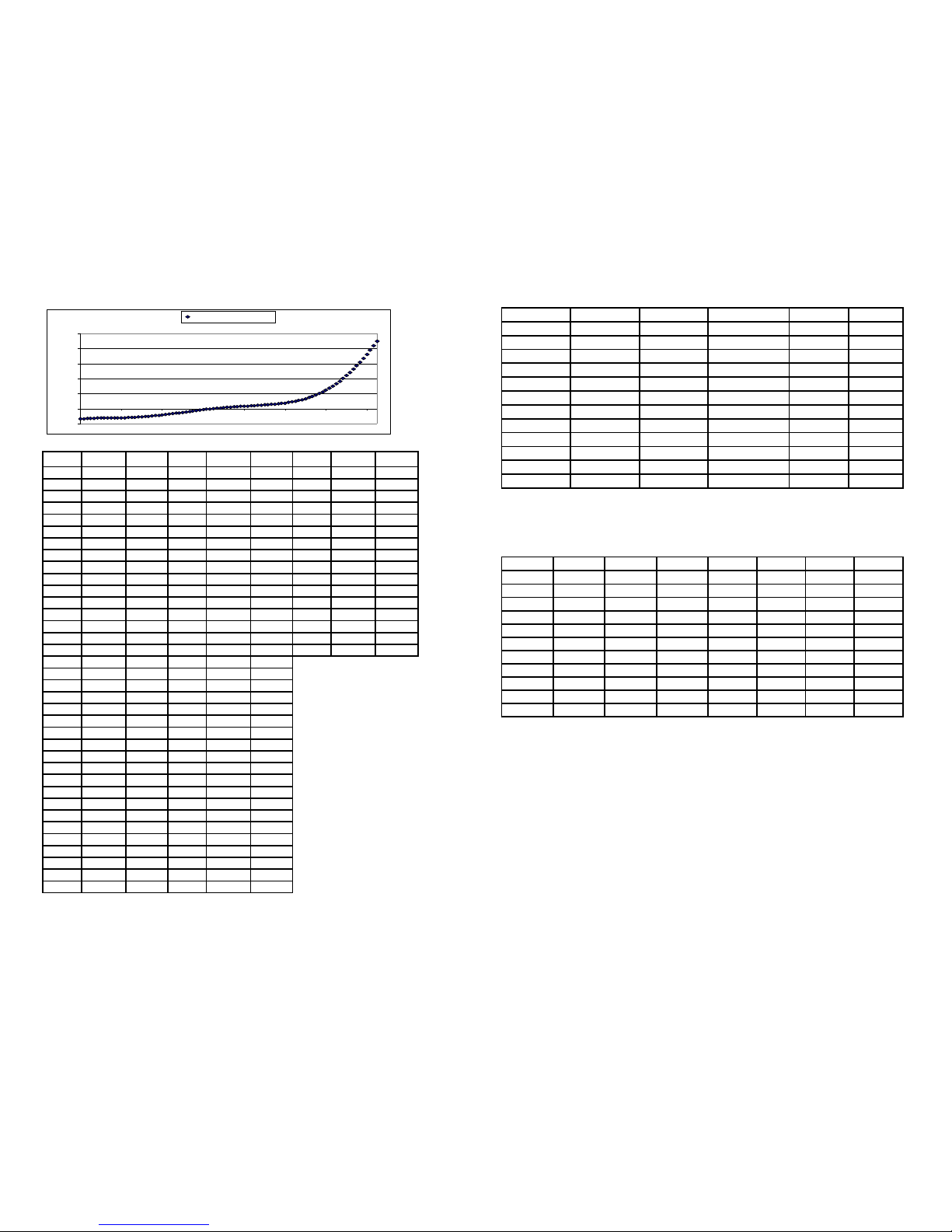
Using the Band Pass Mode it is possible to individually measure the harmonics of
a tone. This is useful for measuring string inharmonicity. Inharmonicity is the
degree to which the frequencies of overtones differ from whole multiples of the
fundamental frequency. For example, to measure the octave harmonic (2nd
partial) of the 4A string, set the PST-4 to 4A and tune the string until rotation is
stopped. Next, set the tuner to 5A and play the 4A string. The string fundamental
will be filtered out, leaving only the 2nd partial in the display. Notice that the
octave harmonic is slightly sharp. Adjust the tuner Calibration until rotation is
stopped. The calibration setting is the level of inharmonicity for the 2nd partial.
2.4 Auto Mode
In Auto Mode the PST-4 tracks the input Note, allowing hands free operation for
most tuning operations. Press the Auto Button to enable Auto Mode and the Auto
LED indicator in the center of the display will light. Press the Auto Button again to
disable. In some situations with very high harmonic content, such as the very low
end of the piano, Auto Mode may not track well and jump between octaves. In
this case, disable Auto Mode and manually select the Note Setting.
2.5 Programmable Temperament Operation
The PST-4 provides 40 user programmable Memory Banks. This allows the user
to program a separate calibration setting for each of the 88 notes. These
calibration settings are recalled whenever the Note Setting is changed. This is
useful for storing piano stretch curves, or for tuning to alternate temperaments.
To enable and select a Memory Bank, press down and hold the Mem Button. The
display will change to [b 1], which signifies Bank 1. While holding the Mem
Button, rotate the Adjust Knob to index to the desired Bank. Release the Mem
Button, and the Mem Indicator in the center of the display will light, showing that a
Memory Bank is enabled. Now press the Cal Button, and note that the calibration
is not adjustable, as it is now set to whatever value is in the Memory Bank. When
in Memory Bank Mode and Calibration Display Mode, the Adjust Knob indexes the
selected Note, as shown by the Note/Octave Indicators inside the Strobe Display.
5
When operating in Memory Bank Mode, the entire Bank can be offset Sharp or
Flat. To adjust the Calibration Offset, press and hold the Cal Button, then rotate
the Adjust Knob. Clicking the Cal Button will change which digit is flashing and
adjusted when rotating the Adjust Knob.
To program a Memory Bank, first select and enable one of the 40 Banks. The
Mem Indicator should be lit. Next, press and hold the Mem Button, then click the
Cal Button to unlock the Bank. Now the Unlock Indicator should be lit as well.
Press the Mode Button if not in Note Display Mode, and select the first note to be
programmed. Press the Cal Button to change to Calibration Display Mode and
then adjust the calibration for the given note to the desired value. Press the Mode
Button again to return to Note Display Mode and repeat until all the desired notes
are programmed. Press and hold the Cal Button and click the Cal Button to relock
the Memory Bank.
There is also a Bank Copy feature to allow you to copy a Memory Bank into
another Bank. To use this function:
1. Hold down the Temp Button while turning the power on. Keep it down
until the PST-4 is running. The Copy Bank Mode is now enabled.
2. Next, press the Mode button. The display changes to [CS 1], which
signifies Copy Source Bank parameter setup.
3. Press the Mode Button to index through the parameters:
[CS n] – Copy Source Bank n
[CD n] – Copy Destination n
[CE -] – Copy Enable
4. Use the Mode Button to index to Copy Source display [CS x] and rotate
the adjust knob to select the Source Bank.
5. Use the Mode Button to index to Copy Destination display [CD x] and
rotate the adjust knob to select the Destination Bank.
6. Use the Mode Button to index to Copy Enable display [CE -] and rotate
the adjust knob to select [CE C].
7. Initiate the copy operation by pressing and holding the Mode Button
down until the display shows [coPy]. When the display shows [donE] the
copy is complete.
8. Turn the Power off, and then on, to return to normal operation mode.
To zero out a previously programmed bank, follow the above procedure using
bank zero as the Source Bank, and the Bank to be zeroed as the Destination
Bank.
2.6 Output Jack Function Selection
The Output Jack can be configured to either output the internal reference
frequency to an amplifier, or pass the Input Jack signal thru to the Output Jack.
Internal jumpers JP8 (2 pins, between the Input and Output Jack), and JP9 (4
pins, below the Output Jack) on the circuit board must be moved to change the
configuration. For signal Input thru to Output configuration, place one shorting
jumper on JP9 and one jumper in the center position of JP8 (shorting pins 2- ).
For Reference Tone output to the Output Jack, remove the jumper from JP9, and
place both jumpers on JP8, shorting pins 1-2 and -4.
6