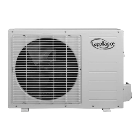
Appliance AWDH 124 User manual

AWDH 124
D
DK
E
FR
FIN
GB
GEBRAUCHSANWEISUNG
BRUGSANVISNING
INSTRUCCIONES DE USO
MANUEL D'UTILISATION
KÄYTTÖOHJE
OPERATING MANUAL
man_AWDH124_1.qxd 29-02-2008 08:50 Pagina 1

Air directional flap
Filter grating
Fresh air system
Power cord
DISPLAY
RED LED power supply is connected
GREEN LED compressor is on
YELLOW LED timer is on
BLUE LED night mode is on
Outdoor Indoor
spirit level
3° INCLINATION
man_AWDH124_1.qxd 29-02-2008 08:50 Pagina 82

LIFT IT UP
HERE LIFT IT UP HERE
Soft terminal
Hard terminal
Rubber cup Water
LIFT IT UP HERE
LIFT IT UP HERE
man_AWDH124_1.qxd 29-02-2008 08:50 Pagina 83

Contents English
1.GENERAL INFORMATION
1.1 INTRODUCTION
1.2 IMPORTANT SAFETY INSTRUCTIONS
1.3 RECEIVING THE GOODS
1.4 HANDLING
1.5 LIST OF ACCESSORIES
1.6 TECHNICAL FEATURES
2.INSTALLATION
2.1 POSITIONING OF THE AIR CONDITIONER
2.2 PAPER TEMPLATE
2.3 DRILLING THE WALL
2.4 FASTENING THE BRACKET
2.5 INSTALLATION OF THE PIPES
2.6 FITTING THE GRATINGS
2.7 FITTING THE AIR CONDITIONER ON BRACKET
3.USE AND MAINTENANCE
3.1 INTRODUCTION OF LCD ICONS
3.2 REMOTE CONTROL FUNCTIONS
3.3 HEATING MODE
3.4 COOLING MODE
3.5 DRYMODE
3.6 FAN MODE
3.7 SLEEPING MODE
3.8 AUTO MODE
3.9 TIMER OFF FUNCTION
3.10 TIMER ON FUNCTION
3.11 FRESH AIR SYSTEM
3.12 INSTALL AND CHANGE THE BATTERY
3.13 MAINTENANCE
3.14 PROBLEM SOLVING
3.15 GUARANTEE CONDITIONS
1. GENERAL INFORMATION
1.1 INTRODUCTION
PLEASE NOTE. Do not dispose of any packaging until the installation of the air conditioner is com-
pleted. After having removed the packing, check that all the content is intact and complete. (See
list of accessories). In the event of missing parts, contact your retailer.This air conditioner has
been designed to cool or heat the air of a room and should only be used for this purpose. The
manufacturer cannot be held liable for damage caused to property or injury to persons or animals
due to incorrect installation, regulation and maintenance or improper use. This air conditioner
contains R410A refrigerant: at the end of its life, the disposal of this air conditioner must be in
accordance with the strict regulation governing the recycling of this product, please operate with
caution during the disposal. Please contact your local authority for regulatory advice. Do not
switch on before having totally assembled the air conditioner and before installing in its correct
operating position. Before starting the appliance, check that it is correctly earthed, according to
the legislation in force in the country concerned.
man_AWDH124_1.qxd 29-02-2008 08:50 Pagina 84

1.2 IMPORTANT SAFETY INSTRUCTIONS
Install the device only when it complies with local regulations, by-laws and standards. The unit is
only suitable for use in dry locations, indoors. Check the mains voltage and frequency. This unit is
only suitable for earthed sockets, connection voltage 220 - 240 V. / 50 Hz.
IMPORTANT
-The device MUST always have an earthed connection. If the power supply is not earthed, you
may not connect the unit. The plug must always be easily accessible when the unit is connected.
Read these instructions carefully and follow the instructions.
-The airconditioner contains a refrigerant and can be classified as pressurized equipment.
Therefore always contact an authorized installation specialist for installation and maintenance of
the airconditioner. It is to be advised that the airconditioner is inspected and serviced on an annu-
al base by an authorized airconditioning engineer.
Before connecting the unit, check the following:
-The voltage supply must correspond with the mains voltage stated on the rating label.
-The socket and power supply must be suitable for the current stated on the rating label.
-The plug on the cable of the device must fit into the wall socket.
-The device must be placed and mounted on a stable surface.
The electricity supply to the device must be checked by a recognised professional if you have any
doubts regarding the compatibility.
-This device is manufactured according to CE safety standards. Nevertheless, you must take care,
as with any other electrical device.
-Do not cover the air inlet and outlet grill.
-Never allow the device to come into contact with chemicals.
-Never spray the unit with or submerge in water
- Do not insert hands, fingers or objects into the openings of the unit.
-Never use an extension cable to connect the device to the electric power supply.If there is no
suitable, earthed wall socket available, have one installed by a recognised electrician.
-For safety reasons take care when children are in the surrounding of the device, as with any
other electrical device.
-Have any repairs and/or maintenance only carried out by a recognised service engineer or your
recognised Zibro supplier.Follow the instructions for use and maintenance as indicated in the
user manual of this device.
-Always remove the plug of the unit from the wall socket when it is not in use.
-Adamaged power cord or plug must always be replaced by a recognised electrician or your sup-
plier.
-Do not operate or stop the airconditioner by inserting or pulling out the power plug. Only use
the dedicated buttons on the airconditioner or on the remote control.
-Do not open the airconditioner when it is in operation. Always pull out the electrical plug when
opening the device.
-Always pull out the electrical plug when cleaning or servicing the airconditioner.
-Do not place gas burners, ovens and/or stoves in the airstream.
-Do not operate the buttons or touch the airconditioner with wet hands.
-It is advised to stay out of the direct airstream.
-Never drink the drain water from the airconditioner.
ATTENTION!
-Never use the device with a damaged power cord, plug, cabinet or control panel.
-Failing to follow the instructions may lead to nullification of the guarantee on this device.
1.3 RECEIVING THE GOODS
The air conditioner is delivered in a protective packaging and is accompanied by an instruction
manual. This manual is an integral part of the air conditioner and should therefore be carefully
read and preserved. When the air conditioner is unpacked, please check that the air conditioner
and the accessory pack are complete and undamaged.
1.4 HANDLING
man_AWDH124_1.qxd 29-02-2008 08:50 Pagina 85

Be fully aware of the weight of the air conditioner before attempting to lift it. Take all necessary
precautions to avoid damaging the product or causing personal injury. It is advisable to remove
the packaging only when the air conditioner has been located in the point of installation.
Carefully remove the adhesive strips positioned on the air conditioner. Packaging components
must be disposed correctly and not left within reach of children, since they are a potential source
of danger.
1.5 LIST OF ACCESSORIES(P0)
1. FASTENING BRACKET
2. REMOTE CONTROL
3. REMOTE CONTROL HOLDER
4. DRAINAGE PIPE
5. EXTERNAL GRATING
6. AIR INTAKE PIPE (160 mm.)
7. AIR DISCHARGE PIPE (150 mm.)
8. KIT OF SCREWS
9. GRATING FIXING CORD
10. INSTRUCTION MANUAL
11. PAPER TEMPLATE FOR WALL DRILLING (See page )
This product has been manufactured to comply with 2006/95/EC and with amendments 92/31/EEC
and 93/68/EEC
Waste electrical products should not be disposed of with household waste. Please recycle where
facilities exist. Check with your Local Authority or retailer for recycling advice.
Any batteries used in the remote control contain materials, which are hazardous to the environ-
ment. They must be removed from the remote control when they reach the end of their life and
disposed of responsibly.
1.6 TECHNICAL FEATURES(P1,P2)
Model AWDH 124
Cooling capacity * W (BTU/h) 2400 (8200)
Heating capacity * W (BTU/h) 2350 (8000)
Rated voltage (V) 230
Absorbed power in cooling** (kW) 1.02
Absorbed current in cooling** (A) 4.48
Absorbed power in heating** (kW) 0.94
Absorbed current in heating** (A) 4.11
Air flow (m3/h) 430
Noise level min-max (dB A) 43-52
Dehumidification capacity*** (L/24h) 57
Optional temperature (remote control) 18-30°C
Fuse 250V-T3.15L
Refrigerant R410A
Global warmer potential (GWP) 1975
Dimensions H/W/D(mm) 548x1008x234
Weight (Kg) 45
*EN 14511-2004
** To be used as indication
*** Moisture removal at 32°C, 80% RH
Environmental information: This equipment contains fluorinated greenhouse gases covered by the Kyoto Protocol. It
should only be serviced or dismantled by professional trained personnel.
This equipment contains R410A refrigerant in the amount as stated in the table above. Do not vent R410A into atmosp-
here: R410A, is a fluorinated greenhouse gas with a Global Warming Potential (GWP) = 1975
man_AWDH124_1.qxd 29-02-2008 08:50 Pagina 86

2. INSTALLATION
2.1 POSITIONING THE AIR CONDITIONER (P3)
To maintain the best performance from your air conditioner, prevent breakdowns or hazards, you
must position it correctly. Please follow the guidelines and instruction below in full, as failure to
do so could cause potential installation problems.
- The air conditioner must be installed on an exterior wall that has access to the outside with a
minimum of 2 meters clearance to the outside.
- The air conditioner must be fitted leaving room all around as illustrated in the paper template
-The wall on which the air conditioner is installed must be sturdy and able to withstand the
weight of the air conditioner.
After determining the best place for installation as described above, please check to ensure that
the wall can be drilled in the chosen area without interfering with other structures or installations
(beams, piers, pipes, wires, etc.). Please also ensure that there are no obstacles on the outside of
the wall, which may obstruct air circulation through the drilled holes, for example: plants and
their leaves, slats or panelling, drain pipes, overflows and gratings, etc.). Any obstruction could
interfere with the correct performances of the air conditioner.
2.2 PAPER TEMPLATE (P4)
Fasten the template to the wall once the following guidelines have been thoroughly checked.
-Do not drill any holes until you are completely confident that there are no obstacles in the area
you wish to drill and there are no obstructions, which could be hidden by the construction of the
wall, for example: Electrical wiring water & gas pipes or supporting lintels or beams.
-Ensure that a spirit level is used, as the air conditioner must be level.
-Follow the installation instructions in full.
2.3 DRILLING THE WALL (P5)
Please note: If you are drilling the hole above ground floor level, please ensure that an area has
been secured and while the holes are drilled the outside area is supervised, until drilling has been
completed.
INTAKE AND OUTLET HOLES
-This operation should be carried out using the proper tools (diamond tip or core borers drills
with high twisting torque and adjustable rotation speed).
-Fasten the template to the wall taking care to check the distance from the floor and or ceiling
and keep it horizontal by using a spirit level.
-Use a pilot drill to mark the centre of each core hole to be drilled.
-Use a core boring head having a diameter of 162 mm to drill the two holes for intake and outlet
the air.
It is recommended that the holes must have a slightly downward inclination of 3-5
degrees to prevent any backflow of water from the pipes.
man_AWDH124_1.qxd 29-02-2008 08:50 Pagina 87

DRAINAGE HOLE (P13)
This air conditioner has a double system to drain the condensated moisture automatically. Before
installing the Air Conditioner choose which is the suitable system for your installation. Please read
carefully the follow instructions.
System “A”: drill a hole through the wall measuring 30 mm in diameter in the position shown in
the paper template. Drainage occurs by gravity. For this reason, it is essential for the drain line to
have a minimum downward inclination at least 3 degrees throughout its length:connect the
drain pipe (from rubber terminal)to the air conditioner (back side) after unplugged the black rub-
ber cup (see picture P13). With this solution you can drain the condensated moisture to a suitable
place.
System “B”: in case of impossibility to install drainage pipe as showed on “A” system, do not
unplug the black rubber cup (picture P13). The condensated moisture will go outside by the two
big pipes (see picture P14). If you choose this solution be sure that the condensate moisture doesn’t
cause any problems to your neighbours.
2.4 FASTENING THE BRACKET (P6)
-Drill the holes for anchoring the fastening bracket to the wall using preferably the 6 holes shown
in black on the paper template. If the wall is not sturdy enough it is advisable to use extra anchor
bolts using the holes showed in grey on the paper template.
-The anchor bolts provided require a 8mm holes; the wall should be inspected to determine if pro-
vided bolts are useful or if it is necessary to use a different anchorage. The manufacturer is not
liable in case of underestimation of the structural consistency of the anchorage made at the time
of installation.
2.5 INSTALLATION OF THE PIPES
-After drilling the holes, the plastic pipes supplied with the air conditioner need to be fitted
through them.
-The pipe with a diameter of 160mm (fresh air intake) has to be fitted in the right hole. The
length of the pipes should be equal to the depth of the wall plus 10 mm. Use a normal hacksaw
to cut the supplied pipes to the correct length. Remember that the modification must to have the
same inclination of the holes (minimum 3 degrees).
-The tube diameter is nearly the same as that carried out using the 162 mm nominal diameter
core drill therefore you may need to slightly force the introduction of the pipe using, in difficult
cases, a normal rubber hammer and a small piece of timber to gently tap the tube into the hole.
-Please use the same instructions to fit the left hand tube (AIR discharge pipe) using the supplied
pipe with a diameter of 150mm. The tube diameter is slightly smaller than that carried out using
the 162 mm nominal diameter core drill.
-Please centre the pipes into the holes in the wall and insulate and seal their perimeters to pre-
vent air and humidity infiltration using polyurethane foam and using plaster as finishing on the
inside wall.
2.6 FITTING THE GRATINGS (P7,P8,P9,P10)
To fit the external two gratings please proceed as follows: familiarise yourself with the fitting of
the grating to the tube, before installation. Insert the cords through the centre of the grating. One
grating fits on the outside of the tube and the other fits inside. The air intake is the bigger hole
and the grating therefore fits on the outside of the air intake tube. Insert the supplied cord into
the hole. Fold the outer grating in half grasping the cord with your free hand. Insert your arm
inside the pipe with the grating and push all the way to the outside. Let the grating unfold and
pull the cord toward you. One grating fits on the outside of the tube and the other fits inside.
With a little patience and manipulation the 2 gratings will fit the end of the tubes. Grasping the
cord, insert your fingers between the fins and pull the grating toward you until the same is proper-
ly slipped in the pipe, keeping the fins in vertical position. If the external grating is accessible to
prevent its removal, it is recommended to fasten it to the wall with wall plugs and screws with a
diameter of 6 mm. Tighten the cord and fasten it to the dent on the internal flanges.
man_AWDH124_1.qxd 29-02-2008 08:50 Pagina 88

2.7 FITTING THE AIR CONDITIONER ON BRACKET (P11,P12)
After checking again that the fastening bracket is securely fastened to the wall, and that any
necessary preparations for electric connection and condensate drainage (if it needs) have
been made, fasten the air conditioner to its supporting bracket. Lift it up by holding the sides
at the bottom. Tilt the air conditioner slightly toward you to facilitate the operation of fas-
tening it to the bracket. The air conditioner can now be pushed firmly against the wall.
Inspect carefully the installation to make sure that the insulating back panel must fit firmly
against the wall and there are no fissures at the back of the air conditioner and that the two
plastic semicircle on the back side of the air conditioner are placed inside of the two plastic
hoses fixed inside the wall.
The appliance should not be installed in a wett cell.
The appliance must be positioned so that the plug is accessible
The appliance shall be installed in accordance with national wiring regulations.
3. USE AND MAINTENANCE
3.1 INTRODUCTION OF LCD ICONS
Icons Meaning Icons Meaning
Auto Fan
Speed
Cooling Airflow
direction
DRY Timer
off
Fan Timer
on
Heating Sleep
Clock Not
Used
man_AWDH124_1.qxd 29-02-2008 08:50 Pagina 89

3.2 REMOTE CONTROL FUNCTIONS
aMODE BUTTON: Set up the air conditioner operating mode
bON / OFF BUTTON: Turn on or turn off the air
cUP BUTTON: Increase the temperature and time
dDOWN BUTTON: Decrease the temperature and time
eFAN SPEED BUTTON: Set up the fan speed
fTIMER ON BUTTON: Set up the time the air conditioner starts
gTIMER OFF BUTTON: Set up the time the air conditioner stops
hCLOCK BUTTON: Adjust the clock
iLOUVER SWING BUTTON: Adjust the airflow direction
jSLEEP BUTTON: Automatically adjusting the setting temperature according the
circadian rule
kRESET BUTTON
lSPARE BUTTON: Under development
3.3 Heating mode
Sequence of the operations
Press the ON/OFF button “ ”, switch on the air conditioner, it will
run by memory mode.
Press the MODE button “ ” set up the mode to heat “ ”, the air
conditioner will run in heating.
Press UP “ ” or DOWN “ ” button, to adjust the setting up tem-
perature
Press the FAN SPEED button “ ”, set up the fan speed “ ” is
low speed, “ ” is middle speed, “ ” is high speed, “ ”
(flashing) is auto speed. For auto fan, the speed is chosen by the dif-
ference of room temperature and setting temperature.
Press the ON/OFF button “ ”, switch off the air conditioner. Next
time when this button is pressed, the air conditioner will operate in
this mode by memory.
man_AWDH124_1.qxd 29-02-2008 08:50 Pagina 90

3.4 Cooling mode
Sequence of the operations
Press the ON/OFF button “ ”, switch on the air conditioner, it will
run by memory mode.
Press the MODE button “ ” set up the mode to cool “ ”, the air
conditioner will run in cooling.
Press UP “ ” or DOWN “ ” button, to adjust the setting up tem-
perature
Press the FAN SPEED button “ ”, set up the fan speed “ ” is
low speed, “ ” is middle speed, “ ” is high speed, “ ”
(flashing) is auto speed. For auto fan, the speed is chosen by the dif-
ference of room temperature and setting temperature.
Press the ON/OFF button “ ”, switch off the air conditioner. Next
time when this button is pressed, the air conditioner will operate in
this mode by memory.
3.5 Dry mode
Sequence of the operations
Press the ON/OFF button “ ”, switch on the air conditioner, it will
run by memory mode.
Press the MODE button “ ” set up the mode to dry “ ”, the air
conditioner will run in dehumidifying.
Press UP “ ” or DOWN “ ” button, to adjust the setting up tem-
perature
FAN SPEED button is “ ”disabled, indoor fan speed always is low
in dry mode. “ ”
Press the ON/OFF button “ ”, switch off the air conditioner. Next
time when this button is pressed, the air conditioner will operate in
this mode by memory.
man_AWDH124_1.qxd 29-02-2008 08:50 Pagina 91

3.6 Fan mode
Sequence of the operations
Press the ON/OFF button “ ”, switch on the air conditioner, it will
run by memory mode.
Press the MODE button “ ” set up the mode to fan “ ”, the air
conditioner will run in fan.
Press UP “ ” or DOWN “ ” button, to adjust the setting up tem-
perature
Press the FAN SPEED button “ ”, set up the fan speed “ ” is
low speed, “ ” is middle speed, “ ” is high speed, “ ”
(flashing) is auto speed. For auto fan, the speed is chosen by the dif-
ference of room temperature and setting temperature.
Press the ON/OFF button “ ”, switch off the air conditioner. Next
time when this button is pressed, the air conditioner will operate in
this mode by memory.
3.7 Sleep mode
Sequence of the operations
Press the ON/OFF button “ ”, switch on the air conditioner, it will
run by memory mode.
Press the MODE button “ ” set up the mode to cool/ “ ” heat “ ”
(heat pump)/auto “ ”, the air conditioner will run in setting mode.
Press UP “ ” or DOWN “ ” button, to adjust the setting up tem-
perature
Press the SLEEP button “ ”, this icon will display on LCD, sleep
function is set up; press it again, cancel the sleep function.
If the sleep function is launched, the fan speed is steady in low
speed.
man_AWDH124_1.qxd 29-02-2008 08:50 Pagina 92

3.8 Auto mode
Sequence of the operations
Press the ON/OFF button “ ”, switch on the air conditioner, it will
run by memory mode.
Press the MODE button “ ” set up the mode to auto “ ”, the air
conditioner will run in heating auto mode. (reference to “emer-
gency operation”)
According to the difference of the room temperature and setting
temperature automatically choose the running mode (cool, heat,
fan, dry). The temperature setting button UP “ ” and DOWN “ ”
are disable.
Press the FAN SPEED button “ ”, set up the fan speed “ ” is
low speed, “ ” is middle speed, “ ” is high speed, “ ”
(flashing) is auto speed. For auto fan, the speed is chosen by the dif-
ference of room temperature and setting temperature.
Press the ON/OFF button “ ”, switch off the air conditioner. Next
time when this button is pressed, the air conditioner will operate in
this mode by memory.
3.9 Timer off function
Sequence of the operations
Press the ON/OFF button “ ”, switch on the air conditioner, it will
run by memory mode.
Press the MODE button “ ” set up the mode to which you want.
Press UP “ ” or DOWN “ ” button, to adjust the setting up tem-
perature
Press the FAN SPEED button “ ”, set up the fan speed “ ”is
low speed, “ ” is middle speed, “ ” is high speed, “ ”
(flashing) is auto speed. For auto fan, the speed is chosen by the dif-
ference of room temperature and setting temperature.
Press the TIMER OFF button “ ”, set up the time the air conditioner
should switch off. Press the button “ ” each time, adjusting up 1
hour; Press the button “ ”each time, adjusting up 10 minutes;
When the time is over,the air conditioner will be switched off auto-
matically. If you press this button again before the air conditioner is
switched off, the timer offsetting will be cancelled.
man_AWDH124_1.qxd 29-02-2008 08:50 Pagina 93

3.10 Timer on function
Sequence of the operations
The air conditioner is switched off.
Press the TIMER ON button “ ”, set up the time the air conditioner
should switch on. Press the button “ ” each time, adjusting up 1 hour;
Press the button “ ” each time, adjusting up 10 minutes; Set up the
operation MODE, TEMPERATURE, FAN SPEED, etc., when the time is
arrived, the air conditioner will start automatically. If the TIMER ON is
pressed again, the TIME ON setting will be cancelled.
3.11 Fresh air system
When the fresh air system is open the air conditioner will change the room air automatically : in
this way new clean and fresh air will flow into the room. You can open or close the fresh air sys-
tem any moment. If the air fresh system is closed the air conditioner performances are higher so
we suggest to maintain the fresh air system closed and open it just a few minutes per day.
3.12 Install and change the battery
-Open the cover of battery, hold the hook and lightly
pull up.
-Insert the battery (AAA,2pcs), the positive must be
same with the mark on the plastic surface.
-Reinstall the cover of battery.
-Inspection: if press ON/OFF button “ “, no icons are
displayed, please install the battery again
Fresh air system
Push here to close
Open position
Close position
man_AWDH124_1.qxd 29-02-2008 08:50 Pagina 94

3.13 MAINTENANCE (P15,P16,P17,P18)
FILTERS CLEANING:
The filters should regularly be cleaned to keep the air conditioner running efficiently. Clean the fil-
ters every two weeks. How to proceed: -Disconnect the air conditioner from the electrical supply.
-Extract the filter grating (P15) on the same direction of the arrow. Rotate the knob as shown on
P17 to liberate the two filters. Proceed to wash them (not use hot water) and replace them only
when they are dried in the same way.
ATTENTION: Do not use the air conditioner without filters as it could seriously damage the air con-
ditioner.
EXTERNAL CLEANING:
-Disconnect the air conditioner from the electrical supply.
-Wipe external surfaces clean with a damp cloth only.
- Do not use an abrasive cloth and/ or solvents, as this may damage the surfaces.
-Do not use excessively wet cloths or sponges, as water stagnation could damage the air condi-
tioner and compromise safety.
3.14 PROBLEM SOLVING
PROBLEM POSSIBLE CAUSES
-The air conditioner does not work.
-The air conditioner does not refrigerate the room
-Strange smell in the room. Water drips from the air conditioner.
-The remote control does not work.
-The air conditioner does not work for 3 minutes when switched on.
POSSIBLE SOLUTIONS
1.Wrong setting of the timer / Check it.
2. Problems on the power supply/Call the service center.
3. The filter could be dirty / Clean it.
4. The room temperature is too high / Wait until the temperature goes down.
5. The temperature is not properly set / Check it.
6. The grids could be obstructed / Check and remove the eventual obstacles.
-Dampness in the room, coming from walls, carpets, furnishing or similar
- Wrong installation of the air conditioner.
- Wrong connection of the drainage pipe.
-Exhausted batteries.
- Wrong insertion of the batteries inside the remote control
-Protection of the air conditioner. Wait for 3 minutes and the air conditioner will start to work
again.
If the supply cord damaged, it must be replaced by manufacturer or its service agent or a
similarly qualified person in order to avoid a hazard.
This appliance is not intended for use by persons (including children) with reduced physical, senso-
ry or mental capabilities, or lack of experience and knowledge, unless they have been given super-
vision or instruction concerning use of the appliance by a person responsible for their safety.
Children should be supervised to ensure that they do not play with the appliance.
man_AWDH124_1.qxd 29-02-2008 08:50 Pagina 95

3.15 GUARANTEE CONDITIONS
The air conditioner is supplied with a 24-month guarantee, commencing on the date of pur-
chase. All material and manufacturing defects will be repaired or replaced free of charge
within this period. The following rules apply:
1. We expressly refuse all further damage claims, including claims for collateral damage.
2. Repairs to or replacement of components within the guarantee period will not result in an
extension of the guarantee.
3. The guarantee is invalidated if any modifications have been made, non genuine parts are
fitted or repairs are carried out by third parties.
4. Components subject to normal wear, such as the filter, are not covered by the guarantee.
5. The guarantee is valid only when you present the original, dated purchase invoice and if no
modifications have been made.
6. The guarantee is invalid for damage caused by neglect or by actions that deviate from
those in this instruction booklet.
7. Transportation costs and the risks involved during the transportation of the air conditioner
or air conditioner components shall always be for the account of the purchaser.
8. Damage caused by not using suitable Zibro filters is not covered by the guarantee.
9. Refrigerant loss and/or leakage because of incompetent (dis)connecting the units is not cov-
ered by the guarantee conditions applicable to this product.
To prevent unnecessary expense, we recommend that you always first carefully consult the
instructions for use. Take the air conditioner to your dealer for repairs if these instructions do
not provide a solution.
man_AWDH124_1.qxd 29-02-2008 08:50 Pagina 96

DISTRIBUTED IN EUROPE BY PVG INTERNATIONAL B.V.
PVG Traffic avg©080229 man_AWDH124_1
iÖSTERREICH
PVG Austria VertriebsgmbH
Salaberg 49
3350 HAAG
tel: +43 7434 44867
fax: +43 7434 44868
email: [email protected]
eBELGIË
PVG Belgium NV/SA
Industrielaan 55
2900 SCHOTEN
tel: +32 3 326 39 39
fax: +32 3 326 26 39
email: [email protected]
qSCHWEIZ
PVG Schweiz AG
Salinenstrasse 63
4133 PRATTELN
tel: +41 61 337 26 51
fax: +41 61 337 26 78
email: [email protected]
2DEUTSCHLAND
PVG Deutschland GmbH
Siemensstrasse 31
47533 KLEVE
tel: 0800 - 9427646
fax: +31 (0)412 648 385
email: [email protected]
6DANMARK
Appliance A/S
Blovstroed Teglvaerksvej 3
DK-3450 ALLEROED
tel: +45 70 205 701
fax: +45 70 208 701
email: [email protected]
5ESPAÑA
PVG España S.A.
Pol. Ind. San José de Valderas II
Comunidad ”La Alameda”
C/ Aurora Boreal, 19
28918 LEGANÉS (Madrid)
tel: +34 91 611 31 13
fax: +34 91 612 73 04
email: [email protected]
3FRANCE
PVG France SARL
4, Rue Jean Sibélius
B.P. 185
76410 SOTTEVILLE SOUS LE VAL
tel: +33 2 32 96 07 47
fax: +33 0 820 34 64 84
email: [email protected]
SUOMI
Appliance Finland Oy
Piispantilankuja 6C
02240 ESPOO
tel: +358 9 4390 030
fax: +358 9 4390 0320
email: [email protected]
FFIINN
4UNITED KINGDOM
Scott Brothers Ltd.
The Old Barn, Holly House Estate
Cranage, Middlewich, CW10 9LT UK
tel.: +44 1606 837787
fax: +44 1606 837757
email: [email protected]
>ITALIA
PVG Italy SRL
Via Niccolò Copernico 5
50051 CASTELFIORENTINO (FI)
tel: +39 571 628 500
fax: +39 571 628 504
email: [email protected]
uNORGE
Appliance Norge AS
Vogellunden 31
1394 NESBRU
tel: +47 667 76 200
fax: +47 667 76 201
email: [email protected]
1NEDERLAND
PVG International B.V.
P.O. Box 96
5340 AB OSS
tel: +31 412 694 694
fax: +31 412 622 893
email: [email protected]
9PORTUGAL
Gardena, Lda
Recta da Granja do Marquês
ALGUEIRÃO
2725-596 MEM MARTINS
tel: + 35 21 92 28 530
fax: + 35 21 92 28 536
email: [email protected]
:POLSKA
PVG Polska Sp. z. o. o.
ul. Kościelna 110
26-800 Białobrzegi
tel: +48 48 613 00 70
fax: +48 48 613 00 70
email: [email protected]
=SVERIGE
Appliance Sweden AB
Sjögatan 6
25225 HELSINGBORG
tel: +46 42 287 830
fax: +46 42 145 890
email: [email protected]
ySLOVENIJA
Monteko d.o.o.
Neubergerjeva 4
1000 Ljubljana
tel: +386 (0)1 437 1273
fax: +386 (0)1 437 1273
email: [email protected]
TURKEY
PVG Is›tma Klima So¤utma Ltd.fiti.
Tepekule is merkezi
Anadolu Cad. No: 40 K:3 D:306
35010 BAYRAKLI/IZMIR
tel: + 90 232 461 51 01
fax: + 90 232 461 51 85
email: [email protected]
TTRR
man_AWDH124_1.qxd 29-02-2008 08:50 Pagina 98
Table of contents
Other Appliance Air Conditioner manuals
Popular Air Conditioner manuals by other brands

Soleus Air
Soleus Air KC-15U owner's manual

Daikin
Daikin EWAQ004BAVP Installer's reference guide

Toshiba
Toshiba RAS-13SKHP-E Service manual

Friedrich
Friedrich WallMaster WS10 Installation and operation manual

Samsung
Samsung AJ NBNDEH Series user manual

Airwell
Airwell Electra JMF Hi wall Series Service manual

Heiko
Heiko JZ026-B1 installation manual

Mitsubishi Electric
Mitsubishi Electric Mr.Slim MS-GK36VA operating instructions

Carrier
Carrier 50VL-D installation instructions

Crosley
Crosley CAE10MR410A13 use & care

Mars
Mars COMFORT-AIRE PS-81G Owner's manual & installation manual

Daikin
Daikin Super Multi NX 3MKS50E3V1B Service manual