Aqua Flo QCUF Operation manual

Installation, Operation & Service Instructions with Part List
Quick Change Ultrafiltration Drinking Water System
Models: QCUF


1
Safe Practices
Throughout this manual there are paragraphs set off by special headings.
NOTE: Note is used to emphasize installation, operation or maintenance information which is important, but does not
present any hazard. Example:
NOTE: The nipple must extend no more than 1 inch above the cover plate.
Caution!: Caution is used when failure to follow directions could result in damage to equipment or property. Example:
CAUTION! Disassembly while under water pressure can result in flooding.
WARNING!: Warning is used to indicate a hazard which could cause injury or death if ignored. Example:
WARNING! Electrical shock hazard! Unplug the unit before removing the timer mechanism or cover plates!
Serial Number
The serial number is located on the rear of the UF manifold housing. Record this number on the warranty page located at
the end of this manual.
NOTE: Do not remove or destroy the serial number. It must be referenced on requests for warranty repair or replacement.
This publication is based on information available when approved for printing. Continuing design refinement could cause
changes that may not be included in this publication.
WARNING! If incorrectly installed, operated or maintained, this product can cause severe injury. Those who
install, operate, or maintain this product should be trained in its proper use, warned of its dangers, and should
read the entire manual before attempting to install, operate or maintain this product.
Attention Aqua Flo Customer:
This system is intended for use on potable water supplies or disinfected water containing cysts. Do not use where water
is microbiologically unsafe or with water of unknown quality. If bacterial contamination is present, a recognized method
of water disinfection is required.
Check with your public works department for applicable local plumbing and sanitation codes. Follow your local codes if
they differ from the standards used in this manual.
The Aqua Flo Quick Change Drinking Water System contains a replaceable ultrafiltration membrane filter. The filtered
water should be tested periodically to verify that the system is performing properly.
Serial Number Label
U - MM-DD-YY-XXXXXX
Date of
manufacture
Serial
Code
Data
Plate
Label Containing
Model #

2
Table of Contents Page
Specifications and Performance Data Sheet .................................................................. 3
Suggested Installation Equipment ............................................................................ 5
Overview of the Aqua Flo Quick Change UF System’s Components............................................... 6
Package Contents......................................................................................... 7
Preparation............................................................................................... 8
Installation
Step 1 Select Component Installation Locations ............................................................10
Step 2 Faucet Installation................................................................................11
Step 3 Install T-Adapter Valve on Water Supply . . . . . . . . . . . . . . . . . . . . . . . . . . . . . . . . . . . . . . . . . . . . . . . . . . . . . . . . . . . . . 13
Step 4 Install Filter System Assembly .......................................................................14
Step 5 Start Up .........................................................................................15
Service and Maintenance ..................................................................................16
Parts Breakdown ..........................................................................................17
Troubleshooting ...........................................................................................19
Warranty Information.......................................................................................20
Quick Change Ultrafiltration Drinking Water System
Installation, Operation & Service Instructions with Part List

3
Specifications and Performance Data Sheet
Daily Production Rate L/day (G/day) . . . 2725.5 (720)
Efficiency Rating. . . . . . . . . . . . . . . . . . . . . 100%
Recovery Rating . . . . . . . . . . . . . . . . . . . . 100%
Typical System Flow Sequence . . . . . . . . Sediment Filter Carbon Block Filter Ultrafiltration Membrane
Carbon Block Filter Dispensing Faucet
Sediment Filter (Stage 1). . . . . . . . . . . . . . 5 Micron
Carbon Block Filter (Stage 2) . . . . . . . . . . 5 Micron
Ultrafiltration Membrane (Stage 3) . . . . . 0.2 Micron
Carbon Block Filter (Stage 4) . . . . . . . . . . 5 Micron
15.8”
2.0”
4.7”
14.3”
Dimensions
2.5”
13.1”
Part # Model Description Stage 1 Stage 2 Stage 3 Stage 4 Faucet
1340201-60 QCUF, STD FAUCET Sediment Carbon Block Ultrafiltration Membrane Carbon Block Standard Chrome 87511
1340201-60-D QCUF, DELUXE CHROME VS888 FAUCET Sediment Carbon Block Ultrafiltration Membrane Carbon Block VS888 Chrome 87580

4
NOTES
1. A softener is strongly recommended for water over 10 gpg hard.
Installing a system without a softener on water with hardness higher
than 10 gpg will reduce the life of the membrane.
2. Additional information on factors that affect UF performance can be
found in the “Performance & Technical Information” section.
Recommended Influent Water Characteristic
Pressure 40 - 100 psi
Temperature 40 - 77 ºF
pH 5 - 10
Chlorine20 - 3 ppm (0 - 3 mg/L)
Chloramine 0 - 3 ppm (0 - 3 mg/L)
Turbidity 0 - 10 NTU
Hardness30 - 10 gpg
Iron 0 - 1 ppm (0 - 1 mg/L)
Bacterial Quality Potable
Filter Cartridge Specifications
* The performance and life of an ultrafiltration membrane or filter element is highly dependent upon pressure, temperature and water quality.
Part # Description Purpose Micron
Rating Capacity Flow Rate
Working
Temperature
Range
Working
Pressure Range
Rated
Life* STAGE
41407001 Sediment Filter Sediment Reduction 5 2000 gallons
(7570 liters)
0.5 gal/min
(1.9 liters/min)
4-38° C (40-
100° F)
207-689 kPa
(30-100 psi) 6 Months 1
41407005 Hollow Fiber
Membrane Ultra Fine Filtration 0.2 2000 gallons
(7570 liters)
0.5 gal/min
(1.9 liters/min)
4-38° C (40-
100° F)
207-689 kPa
(30-100 psi) 12 Months 3
41407002 Carbon Block Filter Chlorine Taste and Odor 5 2000 gallons
(7570 liters)
0.5 gal/min
(1.9 liters/min)
4-38° C (40-
100° F)
207-689 kPa
(30-100 psi) 6 Months Stage
2 & 4

5
Suggested Installation Equipment
Recommended Tools
1. Utility Knife
2. Flathead Screwdriver
3. Phillips Screwdriver
4. Center Punch
5. 7/8” Stepped Drill Bit
6. Finish Hole Saw
7. Porcelain Saw
8. 1/8” & 3/8” Drill Bits
9. Heavy Duty Drill
10. Work Light
11. 2 Adjustable Wrenches
12. Pressure Gauge
12
11
10
1
2
5
6
7
8
3
4

6
Overview of the Aqua Flo Quick Change UF System’s Components
1Manifold Assembly
The manifold assembly serves as the functional hub of the Aqua
Flo system by directing the flow through each of the system’s main
components.
2Sediment Prefilter
The sediment prefilter screens out particulate material, such as dirt,
sand, or rust, which may clog the ultrafiltration membrane.
3Activated Carbon Block Filters
The activated carbon Block filters adsorb any residual tastes and
odors.
4Ultrafiltration Membrane
The Ultrafiltration Membrane mechanically removes microscopic
impurities. Hollow fiber membranes utilize numerous long, narrow
porous filaments packed inside the housing. Product water diffuses
through the membrane while impurities become trapped in the
membrane.
The UF membrane featured in the Aqua Flo system offers exceptional
contaminant adsorption, application versatility, and long life.
The sediment prefilters must be maintained properly to prevent
clogging and premature failure of the UF membrane.
5Dispenser Faucet
The Aqua Flo faucet allows the product water to be drawn from the system by depressing the handle.
NOTE: Cleanliness is essential in the preparation procedure. Be sure to wash your hands thoroughly before handling
filters. The use of surgical gloves is strongly recommended.
1
23
4
5
3

7
1. UF Manifold with Flow Control
2. Sediment Filter
3. Carbon Block Filter
4. Ultrafilter Membrane
5. Carbon Block Filter
6. Faucet and Hardware
7. T-Adaptor
8. Locking Clip (3/8”)
9. 3/8” Elbow
10. Faucet Adapter
11. Locking Clip (1/4”)
12. 1/4” Elbow
13. 4X #10 Phillips Self Tapping Screws
14. 1/4” Tubing (4 ft.)
15. 3/8” Tubing (4 ft.)
16. Installation Template Sheet 11X17
17. O-Ring Small
18. O-Ring Medium
19. Filter Head
Package Contents
4
1
2
3
5
6
9
7
8
15
16
12
11
19 19
17
18
10 13
14

8
Tubing Connectors
The Aqua Flo system features reliable and convenient push-to-connect tubing connectors. Tubing is easily connected and
disconnected from these fittings as follows.
Connect:
Cut the tubing squarely with a sharp knife. Be careful not to crush the tubing. To
avoid leaks, make sure the tubing end is smooth and free of burrs and abrasions.
Lubricate the end of the tube with water or a light coat of silicone and push
the tube end firmly into the fitting. You should feel it push past the O-ring. Avoid
bending the tubing sharply away from the fitting.
Disconnect:
Hold the collar against the fitting body and pull the tube from the fitting.
In the unlikely event that the connection leaks, remove and recut the tubing.
Check the inside of the fitting for debris or O-ring damage. Reconnect.
Push-to-connect tubing connectors grip the outside diameter of the tube. To
help assure a reliable connection, it is important to use high quality tubing with a
consistent outside diameter.
Preparation
1. Cut tube squarely with a sharp knife.
This manual covers the technical aspects of Aqua Flo Quick Change drinking water systems. It is important to read this
manual thoroughly so that you can properly apply, install, and service these systems.
The substances reduced by this system are not necessarily in the customer’s untreated water.
Warranty
A limited warranty is extended to the original end user from Canature WaterGroup. This warranty is printed on the back
cover of the Owner’s Guide.
Application Guidelines
The Aqua Flo system is designed for use on potable water supplies meeting the guidelines outlined in Table 1. The system
should be installed on a home’s cold water line. The flushing stream should discharge through an approved siphon break.
Installation of this system must comply with state and local laws and regulations.
Package Content
The Aqua Flo system is shipped from the factory in carton:
NOTE: The filter elements are shipped in their own sealed packaging. This will help to simplify preparation of the system
and to maximize the shelf life of the UF membrane element.
Product Information
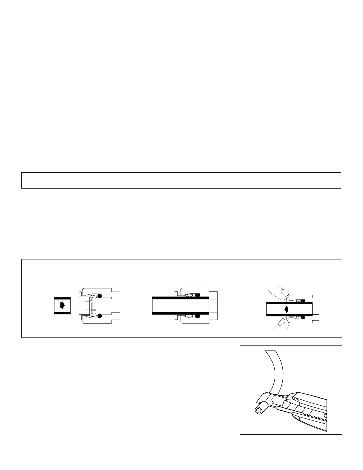
Quick-Connect Fitting
Insertion & Removal of Plastic or
Copper Tubing
1. Simply
push in
tube to
attach.
2. Tube is secured in position. 3. Push in collet from both sides to
release tubing.

9
Figure 1
The exact placement of the components will vary by installation. Although shown beneath a sink, it may be installed
in a basement, crawl space, or in an adjacent cabinet. Regardless of where the system is installed, the flow sequence
described by (figure 1) must be observed.
The Aqua Flo Platinum® drinking water system is designed to be mounted near a sink for easy access to cold water.
Lengths of 1/4-inch and 3/8-inch OD plastic tubing will be required to make this installation.
Evaluate the installation site to determine the easiest path for the plumbing to follow. Take care to make the installation as
neat as possible.
Installation
Aqua Flo Faucet
UF Manifold
1/4” Feed Line
Cold Water Supply
3/8” Product
Water Line
The additional Point of use connection
(Icemakers etc) can be tapped from
here with the use of reducing Quick
Connect Tee (14” X 3/8” X 3/8”)
(Part # PP30121208W).
STEP 2
STEP 3
STEP 4

10
The following steps will enable you to install the system quickly and orderly. Some variation may be necessary depending
on the installation. See page 4 for a check list of tools and materials.
Typical installations follow this sequence:
1. Select Component Installation Locations
2. Faucet Installation
3. Install Adapter Valve on Water Supply
4. Install Filter System Assembly
5. Start-Up
Step 1 – Select Component Installation Locations
• Dispenser Faucet – The faucet is designed to be mounted on the rear lip of the sink. It may be installed in an existing
sprayer attachment hole or in a hole drilled at the time of installation. It may also be mounted to an adjacent counter
top. It should be positioned so that water is dispensed over the sink. A 7/8” diameter hole is required.
• Important considerations:
• Access to the bottom (undersink) of the faucet is required for attachment of product water line.
• There should be no undersink obstructions which would prevent smooth tubing runs to the UF module assembly.
• Filter System Assembly – The filter system assembly is designed to be mounted on any rigid vertical surface such as a
cabinet sidewall, sheetrock in exposed stud. It should be positioned such that there is access to an inlet water source.
The installation should also allow convenient access for servicing.
• Inlet Water Supply Connection – Once a location is chosen for installation of the filter system assembly, select a nearby
cold water line to provide the water source for the system.
NOTE: Follow all local plumbing codes when connecting to service water.

11
Step 2 – Faucet Installation
To simplify its access and installation, we suggest you install the faucet on the rear lip of the sink. It should be evenly
positioned with the sink faucet and spray attachment. Should the spray faucet hole not be available for the installation,
the sink must be drilled.
NOTE: It is recommended retaining the services of a professional counter top craft person when a hole is needed in
granite or other specialty counter top materials.
Sink Drilling Instructions
Stainless Steel Sink
Porcelain Enamel Sink
Follow these basic guidelines when drilling a porcelain sink:
One proven tool is the Relton porcelain cutter kit when used with a slow speed drill (300-400 rpm).
• Drill a pilot hole through the porcelain and base material with the carbide tip drill.
• Build a putty dam around the drill area. Add enough water to lubricate cutters and reduce cutting noise.
• Insert the porcelain cutter into the drill. Place the drill tip in the pilot hole. Check for free movement.
• Apply light pressure to the cutter tool and start the drill motor at low speed (300-400 rpm). When the initial cut has
been made in the porcelain, speed may be increased. After a complete ring has been cut through the porcelain,
change over to the metal cutter. Avoid contacting the outer rim of cut porcelain when drilling.
CAUTION! Avoid high drill speed during penetration of porcelain. A single speed drill can be used at a slow
speed by switching it on and off quickly.
• Use a slow speed and light pressure to cut away the porcelain.
• Stop when you reach the metal under the porcelain. Remove the cutter and clean the porcelain chips from the
surface. Continue cutting through the metal.
NOTE: Ceramic tile counters should be treated like porcelain when penetrating the surface, then treated as metal to
complete the hole with carbide drills. Formica countertops can be drilled with a high-speed wood drill.
Pilot Drill Spring Loaded Porcelain Saw Finish Hole Saw
Penetrate the porcelain to the base
material.
Protect the surrounding porcelain
material.
Use the appropriate tool to drill the
base material.
1. Select and mark the
proper faucet location.
2. Center punch hole to
provide a starting point
for your drill.
3. Drill a 7/8” hole in the sink using a stepped 7/8” drill
bit. If no stepped bit is available, start by drilling
a 1/4” hole. Using this hole as a starting point
progressively drill larger holes. Increase drill size by
1/8” until you reach a 7/8” hole.

12
Faucet
Base
(Remove white protective film)
Plastic Washer
Large Rubber Washer
Small Rubber Washer
Nut
Faucet Adapter
Lock Washer
1
3
5
6
7
8
2
4
Standard Faucet Installation
1. Remove white protective film from faucet base. Install faucet body, small rubber washer, metal base, and large rubber
washer above sink (items 1-4).
2. Install plastic washer, lock washer and nut (items 5-7) onto faucet stem below sink and tighten. Be sure to properly align
the faucet.
3. Install the faucet adapter (item 8). Connect the 3/8" tubing to the faucet adapter.
NOTE: Make certain that the tubing is all the way into the fitting; once inserted pull lightly to make sure it is
locked in place.
Standard Faucet
Drinking Water Line to Faucet
(3/8” Tubing)

13
Step 3 – Install T Adapter Valve on Water Supply (Part # 60010643)
T Adapter
Cold
Water
Supply
T Adapter
To Sediment Filter

14
Step 4 – Install Filter System Assembly
The mounting bracket contains four mounting slots. The holes are sized to accept #10 round head wood screws (supplied).
Some types of surfaces such as particle board or drywall, may require the use of plastic screw anchors or toggle bolts to
provide adequate support for the unit.
1. Tape the paper template included with this unit to the wall with the base of the template on the bottom of the cabinet
(or higher). Be sure to leave adequate space (8 1/2” or more from the centerline) on both sides of the template.
2. Drill 1/8” hole at each location as indicated on the template.
3. Remove template. Thread one of the included wood screws into each hole leaving approximately a 1/2” space
between the screw head and mounting surface.
4. Hang the bracket on the mounting screws. If unit is loose, tighten the screws further.
Install Filter Cartridges
1. Twist the cartridge to lock it into the manifold. (as shown)
Connect System
When cutting plastic tubing, use a sharp utility knife. Cut the tubing squarely. See page 8 for cutting and connecting tubing.
2. Connect 1/4-inch OD plastic tubing
from the feed water supply source
to the system inlet on the manifold.
1. Connect quick connect elbows to
the two open connection locations
on the unit. Firmly push the fittings
into place, then pull back lightly to
lock them in.
3. Connect 3/8-inch OD plastic tubing
from the product water faucet to
the manifold.
3
2
1
1/4” 3/8”
Stage 1
Sediment Filter
Stage 2
Carbon Block
Filter
Stage 3
Ultrafiltration
Membrane
Stage 4
Carbon Block
Filter
Figure 15
2
3
4
1
12"

15
4
Step 5 – Start-Up
1. Check system to verify all components are correctly installed
2. Open inlet valve.
3. Check system thoroughly for leaks. If any are found, shut off inlet and correct the issue.
4. Open faucet to flush carbon fines & sanitization solution. After allowing the system to run for 20 minutes turn
off the faucet
5. System is ready to use
WARNING! Do not drink water produced by the system until the start-up procedure has been
followed completely!
6. Attach locking clips to each elbow
fitting. Clips should slide in behind
collet on the fittings.

16
Service Schedule
To keep the Aqua Flo system operating properly, it is necessary to change the filters and sanitize the system periodically.
Typically, this should be done on an annual basis. Service frequency may vary depending on local water conditions. High
sediment, chlorine, turbidity, or hardness levels may require more frequent service. Use the following as a guide.
As needed
Clean the faucet with a soft cloth, avoid abrasive cleaners.
At least once in 6 months
Replace
•Stage 1 Sediment Filter (41407001)
• Stage 2 & 4 Carbon Block Filter (41407002)
At least once in 12 months
Replace
• Stage 3 Ultrafiltration Membrane (41407005)
Sanitize the system*
Service and Maintenance
Rotate carbon block filters 3 months
after changing
(swap stage 2 & stage 4)
Kit Contents
1/4” Tubing
*Drinking Water
System Sanitization
Kit Preparation -
42903016
Place some rags or a towel
below the system as some
water may leak during this
procedure. Have a pail
handy to drain water into.
1Shut off the water supply to the system
at the adapter valve. Open the faucet
and allow the system to drain completely
Shut off the faucet once drained.
2Disconnect all 4 cartridges and replace
them with the blank cartridges included
in this kit. Disconnect the inlet line from
the system and drain excess water
into a pail.
4Using the tubing included in the kit,
connect the sanitization cartridge between
the adapter valve and the inlet port on
the system.
5Turn on the water at the adapter valve.
If sanitizing an RO allow the system to fill the tank
for 30 minutes. Next, turn on the faucet and
allow the system to run for 30 minutes.
6Leaving the faucet open, shut off inlet
water and let the system drain completely.
7Disconnect the sanitization cartridge from the
inlet line and system. Reconnect the inlet line to
the system and replace cartridges on system.
8Turn on the inlet water and check for leaks. If
sanitizing an RO, allow the tank to fill for 30
minutes and discard the first tank. Allow tank to
refill for 30 minutes.
3Add either ½ teaspoon of household
bleach or 1 packet of Sani-System Liquid
Concentrate (#50036) to the clear
sanitization cartridge and seal the
cartridge tightly.
3 O-ring
Cartridge for
RO Systems
NOTE: if sanitizing an RO be sure to insert the
blank RO cartridge (3 o-rings) in stage 3.
Your system is now clean and ready to use!

17
12
3
4
6
5
7
Parts
# Item # Description Qty.
1 41407001 Cartridge, Quick Change Sediment Filter - Stage 1 1
2 & 4 41407002 Cartridge, Quick Change Carbon Block - Stage 2 & 4 2
3 41407005 Cartridge, Quick Change Ultrafiltration Membrane - Stage 3 1
5 Ci220808W Elbow,1/4” Stem 1
6 Ci221212W Elbow,3/8” Stem 1
7 134040U Manifold, Quick Change Ultrafilter, 4 Stage 1

18
# Item # Description QTY
1 60010643 T-Adaptor 1
2 PP3212U7W Faucet Adapter 1
3 32702004 4x #10 Phillips Self Tapping Screws 4
4 PE-08-BI-0500F-W Tubing 1/4” 4’
5 PE-12-EI-0500F-W Tubing 3/8” 4’
6 PiC1812R Locking Clip 3/8” 2
7 PiC1808R Locking Clip 1/4” 2
8 Ci221212W Elbow 3/8 x 3/8 2
9 Ci220808W Elbow 1/4 x 1/4 2
10 41407554 O-Ring Small
11 41407555 O-Ring Medium
12 92804 Replacement Filter Head
13 87511, 87580, 87581 Faucet, Model Dependent
2
1
4
8
6 7 9
5
3
13
12
10
11
Other Parts
Table of contents
Popular Water System manuals by other brands

Taco Comfort Solutions
Taco Comfort Solutions 0015-MSF-IFC instruction sheet

Atmos
Atmos Aqua clean operating instructions

Reclaim
Reclaim REHP-CO2-160GL Owners & installation manual

Bunn
Bunn Complete Store Water Quality Systems EQHP-TWIN... Specification sheet

Ispring
Ispring WCC31 user manual

KYOKUTOH
KYOKUTOH CWDS-01 manual