AquaLiv A500 User manual

1
AquaLiv Water System – Model A500
Usage & Installation Instructions
Welcome to AquaLiv Water and congratulations! You just purchased the most complete and comprehensive water purification and
enhancement system available today.
The AquaLiv Water System produces energized, structured, alkaline water - just as nature intended.
Enjoy the water!
DAILY USE
Some AquaLiv technologies require water to be moving, while others require water to be still. Therefore, it will take 24 hours of normal
use for the system to ‘charge up’ and up to a week of normal use for maximum power.
After installation, the water may be cloudy or taste heavily of minerals for 2-3 weeks. This is normal as it takes some time for the filters
to become conditioned to the source water. To help alleviate this condition, AquaLiv suggests flushing when an off-taste is noticed or
daily for the first week of use. Simply open the tap fully until the water slows (usually about 3 minutes) and then close. Allow pressure
tank to fill before using again (about 30 minutes).
Cloudiness is the result of two conditions in a newly installed system. The vortex process atomizes air trapped in the system. The other
is hydrogen-bubbles created by the pH/Alkaline/ORP cartridge. The water is safe to drink during this time and the hydrogen bubbles are
actually very healthful! If you do not want to drink the cloudy water, set the glass down and allow the tiny bubbles to rise to the top.
The A500 Purification Module requires filter changes every 12 months. However, each filter set includes a quantity of two
pH/Alkaline/ORP cartridges, as it should be replaced after 6 months of use- don’t forget to mark your calendar. The Tubing Adapters
that screw into the cartridge can be reused once. Each set of replacement filters includes a new set of Tubing Adapters.
To order replacement filters, visit shop.aqualiv.com and select Filter Set FS500.
To order replacement or alternative installation parts, visit shop.aqualiv.com and select Parts.
The AquaLiv Water Revitalizer requires no maintenance. Attempts to open the tank may damage the head and sub-assembly. If the
internal tamper seals are broken, the system warranty will be void.
pH TESTING – pH testing drops and paper strips do not work with structured water. Use a digital pH meter.
WARRANTY – Your Warranty begins with the purchase date on your receipt. Do not lose your receipt!
Your AquaLiv Water System is warrantied against material defects and errors in workmanship for a period of two (2) years. Faucets and RO membranes
have a one (1) year warranty. The warranty does not cover property damage, including flood and/or water damage. All plumbing systems should be
inspected periodically after installation to ensure an absence of leaks that may result in damage to surrounding areas. Warranty is void if product failure
or damage results from freezing, neglect, misapplication, fouling with sediment, or failure to operate system in accordance with the recommended
procedures and guidelines: the RO system must be connected to a potable cold water supply; the hardness of the water cannot exceed 7 grains per
gallon or 120 ppm; source water TDS not to exceed 800 ppm; supply pressure must be between 35 and 70 psi; incoming water temperature not to
exceed 90 degrees F.

2
CHECK YOUR SYSTEM
Please inspect the shipping box to ensure that all system components are accounted for. If any components are
missing or appear to have been damaged in transit, please contact us for assistance.
SYSTEM CONTENTS
SMALL PART IDENTIFICATION CHART AT END OF DOCUMENT
(1x) AquaLiv A500 Purification Module
(1x) AquaLiv Water Revitalizer
(1x) 75 GPD Reverse Osmosis Membrane
(1x) Reverse Osmosis Pressure Tank
(1x) Pressure Tank Valve
(1x) Filter Housing Wrench
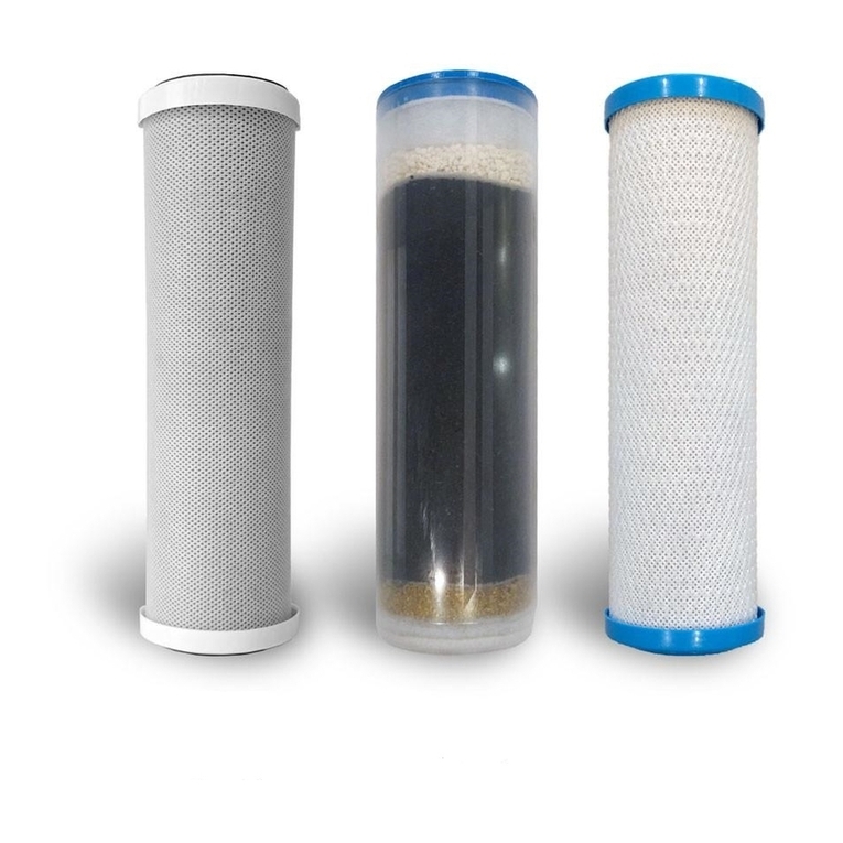
(4x) Filter Cartridges (#1, #2, plus QTY 2 ph/Alkaline/ORP cartridges)
(2x) #10 Hex-Head Screws (to attach Purification Module to cabinet wall)
(2x) 2.5” x 2.5” Double Clip
(2x) 3/8” OD Tubing Adapter
(2x) 3/8” OD Plug In Elbow
(1x) 1/4” OD Threaded Elbow Tubing Adapter
(1x) 3/8” OD Threaded Elbow Tubing Adapter
(1x) Faucet Adapter
(1x) Drain Saddle
(3x) 36” 3/8 OD Flexible Tubing - White
(1x) 6.5” 3/8” OD Flexible Tubing – White
(1x) 36” 1/4” OD Flexible Tubing – White
(1x) 36” 1/4” OD Flexible Tubing – Red
(1x) 1/2” OD Cold Water Connection Tee
(1x) 1/4” OD Plug
(1x) Faucet (if ordered)
INSTALLATION OVERVIEW
AquaLiv suggests a professional plumber install the AquaLiv Water System. However, anyone with handy-person
skills and a few basic tools can accomplish the task. It is best to remove all under-sink contents prior to
installation. If installing the faucet where a dishwasher air-gap/vent currently resides, simply tie up the air-gap at
the highest point available in the under-sink cabinet. Ensure this level is at least a few inches above the drain
connection point of the dishwasher. Remember to always run the disposal prior to operating the dishwasher to
prevent overflows.
AquaLiv is not responsible for damage resulting from improper installation, re-routing of existing fixtures,
or violations of local plumbing codes. Only perform the installation yourself if you feel comfortable with
the job and take full responsibility for your work. If unsure, call a professional plumber for assistance.
TOOLS REQUIRED
•Plumber’s Tape (aka PTFE Tape or Teflon Tape)
•Power Drill/Screwdriver w/ 5/16” Hex-Socket & 1/4” Drill Bit or 3/16” Drill Bit
•Basin Wrench (aka Faucet Wrench, available at most hardware stores)
•Appropriate Drill or Hole-Cutter for sink/countertop material (if no hole currently exists for faucet)
•Utility Knife w/ New Blade & Cutting Board
•Adjustable wrenches and/or small Chanellock-type pliers
•Tape Measure

3
INSTALLATION PRO-TIP
Tubing is installed by pushing the tubing ends into the push-fit connections on the system components. Push in tubing
until fully seated. You may need to wiggle the tubing while pushing. Approximately 5/8” of tubing will slide into a fitting
when fully inserted.
To remove tubing from a fitting, pull out on tubing while simultaneously pushing in on the ring surrounding the tubing.
INSTALLATION
STEP #1: Situate and Arrange AquaLiv Water System Modules in Under-Sink Cabinet
1) Situate system Modules and Pressure Tank in under-sink cabinet.
2) The A500 Purification Module is wall mounted and often best installed just a few inches back from the cabinet
opening. This will allow for easy filter changes in the future.
3) The Modules will be connected with the included flexible tubing lengths. The Purification Module IN will be connected
to the Cold Water Connection Tee. The Purification Module OUT will be connected to the inlet of the ph/Alkaline/ORP
cartridge on top of the membrane (see photo on left side of Page 6). The outlet of the pH/Alkaline/ORP cartridge
connects to the inlet of the Water Revitalizer. The outlet of the Water Revitalizer connects to the AquaLiv faucet.
Ensure the preferred position of the Modules is possible within the length of the 36” lengths of tubing.
4) The Pressure Tank also connects to the A500 Purification Module, at the backside of the outlet filter. There are two
places to connect the tubing. Depending on whether you choose to mount the A500 Purification Module on the right or
left side of the under-sink cabinet, choose the port pointing to the back of the cabinet. The blue pigtail hanging near
the fitting should be connected to the remaining opening as depicted in the photos below. Connect the pigtail.
IMPORTANT NOTE
Module locations must allow for gradual bends in the flexible tubing – no sharp bends or 90-degree angles.
5) If everything looks like it will fit together without problems, please remove the modules from the cabinet for the time
being. If not, re-arrange Modules.

4
STEP #2: Install the Cold Water Connection Tee (do NOT use plumber’s tape)
1) Close the cold water supply valve to the kitchen faucet. Open the cold side of the kitchen faucet to relieve pressure
and then close again.
2) Disconnect the cold water supply tube/hose/pipe at the end connected to the kitchen faucet. (Do not remove the
tube/hose/pipe from the cold water supply valve)
3) Screw the Cold Water Connection Tee onto the kitchen faucet until you feel resistance, then turn an additional 180°-
360°. Connection should be tight, but over-tightening can break the tee or damage faucet.
4) Connect the tube/hose/pipe to the Cold Water Connection Tee. Do not over tighten.
STEP #3: Install faucet
NOTE: Not all parts contained in the faucet box will be used during installation. Please refer to the diagram below.
1) Gather the parts indicated in the diagram above and discard the unused parts.
2) If drilling a hole, locate and mark the desired location and drill a 1/2” hole. If using an existing hole, remove hole plug.
3) Assemble the Brass Escutcheon and Black Rubber Washer onto the faucet stem as shown and place in hole.
4) On the underside of the counter top, slide Black Locating Washer and Star Lock Washer up onto stem.
5) Screw Nut onto stem by hand and spin it up the stem until the faucet is held firmly in place.
6) Arrange the spout and handle to their optimal positions on the faucet base.
7) Use a 9/32” wrench or Basin Wrench to tighten the Nut until the faucet is secure on the countertop.
8) Install the Faucet Adapter onto the bottom of the stem. Do not use plumber’s tape or other sealants.
9) Insert one length of the 36” 3/8” OD white tubing into the Faucet Adapter ensuring that 5/8” of tubing slides into the
adapter.

5
STEP #4: Install the Drain Saddle
Drain Saddles are designed to be installed on standard 1-1/2” OD drain-pipe. Install drain saddle above (and before) the
trap and on the vertical or horizontal tailpiece. Never install the Drain Saddle close to the outlet of a waste disposal or
plugging of the RO drain line may result.
1) Mark the point on the drain-pipe where you would like to install the Drain Saddle. If drain-pipe is plastic, drill a 1/4”
hole through the wall of the pipe (just at the mark, not though and out the opposite side). If drain-pipe is metal, drill a
3/16” hole instead.
2) Locate and open the Drain Saddle kit. Locate the foam square and push out the center hole. Remove the yellow
backing and stick the foam over the hole on the pipe, placing it square with the run of the pipe.
3) Hold section of Drain Saddle with the tubing connection over the drain-pipe, with the tubing connection aligned
perfectly with the hole in the pipe.
4) Attach the other half of Drain Saddle using the included nuts and bolts. Tighten.
STEP #5: Attach “Threaded Elbow Tubing Adapters” to Purification Module
1) Wrap the threads of the Threaded Elbow Tubing Adapters with plumber’s tape. 12 wraps are required with most
brands of tape. Screw in the “1/4” Threaded Elbow Tubing Adapter” into the Purification Module inlet. The inlet
adapter can point in any direction that is best for the inlet tubing connection. Screw in the “3/8” Threaded Elbow
Tubing Adapter” into the Purification Module outlet. The outlet adapter should be pointed toward 1pm. Use care not to
cross-thread the Adapters while screwing them in.
STEP #6: Attach Reverse Osmosis Membrane to Purification Module
1) Remove the pH/Alkaline/ORP cartridge from the Purification Module by pulling it out of the retainer clips.
2) Unwrap the Reverse Osmosis Membrane (discard the small part wrapped with it as it will not be used). Remove the
label from the Membrane by peeling it off.
3) Set the Membrane on top of the retainer clips so that the white port points back and is on the Outlet side of the
system. Push Membrane onto the retainer clips ensuring it is centered left to right.
4) Insert the Red, White, and Blue tubing into the corresponding, color-coded ports of the membrane. Ensure tubing is
fully inserted.
5) Ensure your Purification Module now matches the photo below:

6
STEP #7: Attach ph/Alkaline/ORP Cartridge to Purification Module, Install 1/4” OD Red Tube
1) Pry the blue plugs from the ends of the Cartridge.
2) Locate the two 3/8” OD Tubing Adapters and screw them into the ends of the Cartridge until o-rings are fully seated.
Plumber’s Tape is generally not required on these fittings.
3) Locate the two 3/8” OD Plug In Elbows and push them into the cartridge end fittings until fully seated.
4) Locate the two 2.5” x 2.5” Double Clips and snap them onto the Reverse Osmosis Membrane and then snap the
pH/Alkaline/ORP cartridge onto the Membrane per the photo below-left.
5) Locate the small section of white 3/8” OD tubing and connect Cartridge to the Purification Module outlet per the photo
below-left. Ensure tubing is fully inserted into the fittings.
6) Locate the 36” section of 1/4” OD Red Tubing. Insert tubing fully into the port identified in the photo below-right.
STEP #8: Attach Purification Module to Cabinet Wall, Install Filter Cartridges
1) Using a power screwdriver and hex-socket, screw mounting screws into cabinet wall. Do not fully-seat screws - allow
just enough room to slip the Purification Module bracket over the screws. Screw locations noted below:
a) Screws should be spaced exactly 10” apart and 15” high
b) The screw closest to the cabinet opening should be 3.5” back from the opening
2) Slip Purification Module onto the mounting screws.
3) Use the Filter Housing Wrench to loosen the #1 and #2 Filter Housings on the Purification
Module. NOTE: The housings unthread counter-clockwise when seen from the bottom.
Facing head-on, the housings should be turned to the left. Once loosened, the housings
should be unscrewed by hand.
4) Refer to the filter identification diagram. Unscrew the #1 Filter Housing from the
Purification Module. Unwrap the #1 Filter Cartridge and place into the #1 housing. Ensure
the filter cartridge sits over the alignment pipe at the bottom of the housing and that the
top & bottom gaskets are in place.
5) Gently thread the housing back onto the Purification Module, ensuring it screws on
evenly. Tighten by hand.
6) Repeat the previous two steps for the #2 Housing/Filter.
7) Once the housings have been hand-installed, use the Filter Housing Wrench to tighten them approximately 1/8 turn
more. This will seat the o-rings properly.

7
Handle'down'='momentary'
flow'
Handle'up'='constant'
flow'
STEP #9: Connecting the Components
IMPORTANT NOTE
Only shorten tubing if your installation requires it. Cut tubing using a utility knife and cutting board. Cuts must be
perpendicular to tubing-length and be burr-free. Messy cuts can damage fitting o-rings and result in leaks.
1) Locate the Pressure Tank and Pressure Tank Valve. Wrap the threads on the Pressure Tank with plumber’s tape. 10
turns is sufficient with most brands of plumber’s tape. Screw on the valve until seated firmly. Ensure the valve is open
by aligning the handle in the direction of the tubing connection.
2) Place the Water Revitalizer and Pressure Tank back into the desired locations under the sink.
3) Using the 36” length of 1/4” OD white tubing, connect the Cold Water Connection Tee to the Purification Module inlet.
Ensure tubing is fully inserted.
4) Using a 36” length of 3/8” OD white tubing, connect Pressure Tank to the fitting on the backside of the outlet filter of
the Purification Module. Ensure tubing is fully inserted.
5) Using a 36” length of 3/8” OD white tubing, connect the outlet of the pH/Alkaline/ORP cartridge to the inlet of the
Water Revitalizer. Ensure tubing is fully inserted.
6) Locate the white tubing previously attached to the system faucet. Connect it to the outlet of the Water Revitalizer.
7) Locate the 36” 1/4” OD red tube previously attached to the Purification Module. Insert the remaining end into the Drain
Saddle. Ensure tubing is fully inserted.
8) All connections should now be complete! Double check your installation to ensure all modules/components are
connected.
IMPORTANT NOTE
Tubing that is not fully seated will result in leaks.
STEP #10: Filling and Flushing AquaLiv Water System
1) Open the system faucet fully and then slowly open the cold water supply valve.
IMPORTANT: Watch for leaks and be ready to shut off the cold water supply.
NOTE: The basic faucet has a ‘constant flow’ feature that simplifies this step.
2) The system will fill for 20-60 minutes, depending on the water pressure. During this time, air will be emitted from the
faucet and a soft clicking sound will be heard from the Purification Module. The clicking sound indicates the

8
Purification Module is operating correctly. During this time, dry off all tubing and fittings with a dry cloth or paper
towels.
3) Once water emerges from the faucet, allow it to flow for five (5) minutes and then close the system faucet. Now water
will fill the Pressure Tank and the system will slowly pressurize.
4) When the Purification Module stops clicking (up to 30 minutes or more), the Pressure Tank is full and the system is
pressurized.
5) Open the system faucet and allow water to flow fully until it reaches just a trickle in speed. Close the faucet and allow
the Pressure Tank to fill again. Repeat twice more.
6) Wait 24 hours and complete two more flushes per steps 4 & 5 above. The water is now safe to drink.
7) It may take up to one week of regular use for water to be fully enhanced.
STEP #11: Inspect for leaks
1) Feel all connections for water drops or dampness. Inspect with a flashlight if needed. Any drips or dampness may
indicate a loose or faulty connection.
2) If a leak is suspected, always complete the following steps before servicing the system:
(1) Close the Pressure Tank valve
(2) Close the cold water shut off valve supplying the system
(3) Open the system faucet to relieve pressure then close again
Leaks can develop with time. Be sure to inspect the system and entire under-sink area with a flashlight. Do so
daily for a couple of weeks. AquaLiv is not responsible for leaks or flood damage of any kind. Be vigilant.
CONGRATULATIONS
The AquaLiv Water System in now installed!
IN AN EMERGENCY
Should the water supply to the AquaLiv Water System need to be shut off while cold water is wanted at the kitchen faucet:
1) Close the cold water supply valve
2) Close the Pressure Tank Valve
3) Open the AquaLiv faucet to relieve pressure, then close
4) Remove the tube supplying the AquaLiv Water System from the Cold Water Connection Tee
5) Insert the included 1/4” OD Plug into the Tee
IMPORTANT NOTE – PLEASE READ
After installation, the water may be cloudy or taste heavily of mineral for 2-3 weeks. This is normal as it takes some time
for the filters to become conditioned to the source water. To help alleviate this condition, AquaLiv suggests flushing when
an off-taste is noticed or daily for the first week of use.
Cloudiness is the result of two conditions in a newly installed system. The vortex process atomizes air trapped in the
system. The other is hydrogen-bubbles created by the pH/Alkaline/ORP cartridge.
The water is safe to drink during this time and the hydrogen bubbles are actually very healthful! If you do not want to drink
the cloudy water, set the glass down and allow the tiny bubbles to rise to the top.

9
SMALL PART IDENTIFICATION CHART
1/4” OD THREADED ELBOW TUBING ADAPTER 3/8” OD THREADED ELBOW TUBING ADAPTER
1/2” OD COLD WATER CONNECTION TEE 2.5” X 2.5” DOUBLE CLIP
DRAIN SADDLE FAUCET ADAPTER
3/8” OD PLUG IN ELBOW1/4” OD PLUG
PRESSURE TANK VALVE 3/8” OD TUBING ADAPTER

10
CHANGING THE ALKALINE CARTRIDGE
1. Close the Cold Water Supply Valve
2. Close the Pressure Tank Valve
3. Open the AquaLiv faucet. When water flow slows to a trickle, close the AquaLiv faucet
4. Prep the area beneath the filter housings with towels to catch spillage
5. Remove the old alkaline cartridge by releasing the tubing from the fittings on the cartridge (to remove
tubing from a fitting, pull out on the tubing while simultaneously pushing in on the ring surrounding the
tubing)
6. If reusing the fittings on the old alkaline cartridge, remove and install onto the new cartridge. If using
new fittings, install the new fittings onto the cartridge. O-rings on the fittings should be fully seated
against the cartridge to prevent leaks
7. As you are facing the front of the purification module, ensure the alkaline cartridge flow arrows point
from right to left. Install the new alkaline cartridge on the purification module by pushing the tubing
into the fittings until fully seated, about 5/8”
8. Open the Cold Water Supply Valve
9. Open the Pressure Tank Valve
10. Dry the system and undersink area with a towel and inspect for leaks
11. You can now continue to use the AquaLiv system normally. After a bit of use, some air will exit the
faucet. This is normal. A bit later you may notice an off-taste. At this point, open the AquaLiv faucet
and let the system run until water slows to a trickle, then close the faucet and allow the system to fill
(1-2 hours) before using again. Perform this flush each time you notice an off-taste which can go
away between one and three flushes
Table of contents
Other AquaLiv Water System manuals