Aquasana OptimH2O AQ-RO-BASE User manual

Owner’s Manual — AQ-RO-BASE
Aquasana OptimH2O™ Drinking Water System
Reverse Osmosis Filtration Technology
Welcome to the Aquasana experience. You are about to enjoy clean, clear water and the peace
of mind that comes from knowing award winning filter technology is working for you.

WARNING: Using a qualified installer is recommended.
Proper installation is the responsibility of the installer.
Product failure due to improper installation is not covered under the warranty.
NOTE: Keep these instructions for future reference
PLAN FOR INSTALLATION
Prior to installation, we recommend you read the entire manual to familiarize yourself with the
system, and help you determine the best location for installation. Please check and comply with
all local plumbing codes.
PREPARE SITE FOR INSTALLATION
NOTE: If you have metal drain pipes, consult a plumber for installation of drain connection.
1. Prior to installation, close the cold water shut-o valve.
2. Temporarily place system manifold and tank
into the under sink cabinet or desired location
to ensure adequate space and proper positioning.
3. ⁄" white tubing will be used to connect manifold to tank, and from faucet stem to manifold.
Measure out ⁄" white tubing from the top of the tank to the outlet side of the system
manifold and mark ⁄" tubing. Then measure remaining length of ⁄" tubing from the
manifold to the desired location of the faucet hole to ensure there will be enough ⁄" tubing
available for both connections. Wait to cut tubing and follow instructions below.
4. Remove system and tank from under your sink to begin installation.
INSTALLATION OVERVIEW
Step 1 - Install Brass Tee Fitting
Step 2 - Install RO System Manifold
Step 3 - Install Water Storage Tank
Step 4 - Install RO Faucet
Step 5 - Install RO Drain Connector
Step 6 - Connect Tubing
Step 7 - Stage 1–3 Filter Installation
Step 8 - Sanitize, Pressure Test, Purge System
REQUIRED TOOLS & MATERIALS
• Basic plumbing knowledge
• Tape Measure
• Utility Knife
• Screwdriver (Phillips)
• ⁄" & ⁄" Drill Bits/Drill
• Adjustable Wrench
• Bleach
• Safety Glasses
• Pencil
• Masking Tape
• Pan or Bucket
WHAT’S INCLUDED
A System Manifold
B Carbon Filter Sump
C Membrane Filter Sump
D Carbon Filter Sump
E RO Faucet Spout
F RO Faucet Body
G Water Storage Tank
H Tank Connector
I Eye Dropper
J Plumber’s Tape
K Drain Connector
L Nuts & Bolts
M Foam Seal
N O-Ring+Faucet Base
O Toggle Bolts
P Flow Restrictor
Q 90° Elbow
R Mounting Screws
S Brass Tee
T Tubing ⁄" Red
U Tubing ⁄" White
V Tubing ¼" White
W Carbon Filter Cartridge
X Carbon Filter Cartridge
HOT
OptimH2O™
Stage
RO Membrane
AQ-RO3-RO
OptimH2O™
COLD
A
B DC
E
F
N
G
H
K
S
U
U
V
T
A
B
F
G
H
I JK
L
M
N
O
PQR S
TUV
WXC D
E
OptimH2O™

INSTALL BRASS TEE FITTING
1Turn o the cold water supply to the sink.
2Turn on the kitchen faucet to release pressure and allow water to drain from the line.
3Disconnect the cold water line from the ½" threaded stem on the bottom of the kitchen
faucet. Attach threaded ends of supplied brass tee to the cold water supply line and shut-o
valve; tighten using an adjustable wrench.
4Attach ¼" white tube to the brass tee:
A. Slide the compression nut onto the white tubing.
B. Slide the plastic sleeve onto the white tube.
C. Place brass insert into the opening of white tube.
D. Push the tip of the white tubing into the opening of the brass tee.
E. Slide the compression nut onto the threads of the brass tee.
F. While holding the white tube in place, tighten the compression nut to compress the plastic
sleeve and create a seal. NOTE: Use a wrench to ensure complete seal. Avoid over tightening.
5Do not connect the other end at this time.
1On the nipple on top of the tank, apply plumber’s
tape 4 or 5 times clockwise around in the same
direction as the threads.
2Hand tighten the tank connector onto the tank
nipple until secure. NOTE: Do not cross thread or
over tighten.
3Using mount stand, place tank near the system
manifold. Measure ⁄" white tubing to the outlet
side of the system manifold and ensure you
have enough tubing to connect tank and system
manifold as well as enough left to attach faucet
stem and manifold. Cut ⁄" white tubing.
Stage
RO Membrane
AQ-RO3-RO
OptimH2O™
OptimH2O™
A B C D E F
OptimH2O™
OptimH2O™
OptimH2O™
OptimH2O™
OptimH2O™
OptimH2O™
OptimH2O™
A B C
2
1
INSTALL SYSTEM MANIFOLD
1 Select an easily accessible area under the sink to mount system
manifold. You want to allow at least a 4 to 6 inch clearance
below the filters to the floor to allow ample space for filter
changes. To help gauge the right location for your system
manifold, insert first and third stage filter sumps into manifold.
Insert sumps by aligning top connection points and push up and
to the right until sumps are locked in.
2Mark wall placement for mounting screws using
built-in bracket on back of manifold. Make sure holes
are as level as possible.
3 Drill two pilot holes for mounting brackets using ⁄"
drill bit for the system manifold. NOTE: Use caution
not to drill into anything beyond the cabinet wall.
4Insert mounting screws into the wall leaving
approximately ⁄" of each screw exposed.
5Remove first and third filter sumps from manifold by turning each sump to the left and
pulling down before hanging manifold on wall. Mount manifold on wall and screw in. Be
careful not to over tighten.
4Install the ⁄" white tubing to the tank:
A. Push the tubing through the nut, collar and sleeve into the connector.
B. Unscrew the compression nut from the tank connector to ensure that the tubing is
connected all the way through the collar and sleeve.
C. Slide the nut to the threads and tighten with a wrench. Avoid over tightening.
INSTALL WATER STORAGE TANK

INSTALL RO FAUCET
You will need a sink top hole between 1½" and 15/8" in diameter. If drilling a new hole, ensure
faucet body will mount flat against surface and that there is sucient tubing between faucet
body and system manifold. NOTE: Drilling holes into solid surfaces or surfaces made of stone
should only be performed by a qualified and certified installer.
1Attach remaining ⁄" white tubing to stem on faucet body by wetting tubing end and
inserting into faucet stem fitting approximately ⁄" until it stops. Gently tug on the tubing
to ensure it is firmly seated in fitting.
NOTE: Do not connect ⁄" white tubing from tank to faucet.
2 Mount faucet base by pushing toggle bolts through the sink hole until faucet base is flush
with countertop. Position toggle bolts under sink surface being certain faucet stem will
not be obstructed. Loosely fasten faucet base to countertop by tightening toggle bolts,
alternating between left and right sides to evenly tighten. Leave loose to adjust faucet
body as desired.
3Route the tubes attached to faucet body through the faucet base and through hole in sink
until approximately " of tubing remains above sink.
4Turn ¼ clockwise and holding faucet base firmly, mount faucet body to faucet base. Adjust
faucet body handle to desired location.
5To tighten faucet, hold base firmly to keep it from moving while turning faucet body ¼ turn
counterclockwise. Tighten toggle bolts evenly, making sure not to over tighten.
6Mount faucet body to faucet base; turn ¼ turn clockwise until it locks.
7Attach faucet spout to faucet body by screwing spout nut to body.
INSTALL RO DRAIN CONNECTOR
WARNING CAUTION
Be sure that all electrical appliances and
outlets are turned o at the circuit breaker
before working in the cabinet area.
Please wear safety
glasses to protect
eyes when drilling.
1Identify drain outlet location.
2Remove protective cover from back of foam seal.
3Knock center hole out, align holes, and attach to front plate of drain connector.
4Allowing room for drilling, position the drain connector on sink drain pipe above drain trap.
5Securely tighten nuts and screws.
6Using drain connector port as drill guide, drill ⁄" hole through wall of drain pipe. Be sure
not to penetrate opposite side of pipe, and be careful not to damage side of drain port
fitting.
COLDHOT

WARNING:
Faucet will leak
if restrictor is
not installed
CONNECT TUBING I: Brass Tee to Manifold “INLET” (¼" white tubing)
1Take the white tubing leading from the brass tee and insert it into the manifold port
labeled “INLET”. Remember to push it all the way in until it stops.
II: Manifold to Faucet (⁄" white tubing already attached to faucet)
1 Insert the ⁄" white tubing (that was installed in step 4) from the faucet into the manifold
port labeled “FAUCET”.
III: Manifold to Tank (⁄" white tubing already attached to tank)
1 Take the white tubing leading from the storage tank and insert it into the manifold port
labeled “TANK”. Remember to push it all the way in until it stops.
IV: Air Gap to RO Membrane (¼" red tubing from faucet)
1 Insert restrictor into the end of the red tubing.
2Attach ¼" red tubing to the ° elbow until it stops.
3 Attach ¼" ° elbow to the membrane drain port.
V: Faucet to Drain Connector (⁄" red tubing from faucet)
1 Take the ⁄" red tubing from faucet and insert it all
the way into the drain connector.
COLD
Hose Connections:
¼" White Brass Tee to Manifold
3⁄8" White Manifold to Faucet
3⁄8" White Manifold to Tank
HOT
I
I
II
III
¼" Red Membrane to Faucet
3⁄8" Red Faucet to Drain Connector
IV
V
IV
II
III
VOptimH2O™
Stage
RO Membrane
AQ-RO3-RO
OptimH2O™
12
3
0.95”
Tube Marking Guide:
(actual size)
Tubing Dont’s
DO NOT cut tubing too short. Always double check
measurements before cutting.
DO NOT bend or crimp or kink tubing.
DO NOT discard excess tubing.
Tubing Do’s
Insert tubing ALL THE WAY IN to prevent
leaking. In most cases, up to nearly a full inch.
Wet end of tubing to more easily insert into all
inlets and outlets.
Cut excess tubing in order to prevent crimping,
kinks, loops or folds.

SANITIZE, TEST & PURGE
Sanitize
Note: Sanitization is recommended immediately after RO Filter System installation and any inner-part
servicing. The person sanitizing should have clean hands during this process.
1Shut o water supply to RO system.
2 Open faucet. If tank is not empty, allow to
drain until empty.
3 With included eyedropper and household
bleach (5.25%), disconnect white tubing
from the manifold outlet labeled “TANK”.
Note: Bleach needs to be handled
according to manufacturer’s instructions.
4 Add 3ml bleach into open end of tank white
tubing.
5 Reconnect the tank from the tube into the
manifold outlet labeled “TANK”. Be sure to
push tubing in all the way.
6 Sanitation will be completed during the following pressure test and purge. Important:
Bleach must be completely removed from system before drinking water. See Purge
instructions below.
Pressure Test
Important: Complete sanitization prior to pressure test.
1 Open cold water supply valve to RO Filter System.
2 To purge air from the plumbing system, open kitchen faucet. Close faucet when water runs
smooth.
3 Confirm RO faucet is closed.
4Within approximately 2 hours, pressure will start to build in the RO Filter System. Carefully
inspect all connections and fittings while this pressure buildup occurs.
5 Check for leaks. If leaks are found, fix by ensuring all tubing is cut squarely and fully inserted.
Also confirm there are no scratches, dents or notches at tubing end. If there are, squarely cut
1" o and re-insert.
Note: When RO Filter System is first pressurized, water may project
from faucet air gap hole until air is passed from RO Filter System.
Purge
1Open RO faucet and let water flow through system for 24 hours.
Note: Flow rate will be slow during this time.
2Close RO faucet after purge is complete.
Note: Your RO Filter System is ready for use when purge is complete, however, you will not have filtered
water immediately. It takes 1-3 hours to completely fill the tank. The flow rate will be less than your
kitchen faucet. Water will run to the drain while the RO Filter System is filtering water – even when not in
use. This is normal. Water going to drain will stop automatically when tank is at capacity.
STEP FILTER INSTALLATION
Before you begin: make sure the cold water valve is shut o and there is no pressure in the system. Carbon
(red) filter cartridges will come pre-installed in their cartridge sumps.
1Attach red carbon sump to the 1st stage position on the inlet side of the system manifold.
Make sure all connection points are aligned and push the top of the sump up and into the
system manifold. Turn it towards the right until it locks in.
2Repeat step 1 for the 2nd Stage RO membrane that goes in the center, and for remaining
carbon cartridge in the 3rd stage position on the outlet side of the system manifold.
OptimH2O™
Stage
RO Membrane
AQ-RO3-RO
OptimH2O™
1
1
2
3
3
2
1
3
3
2
1
A
B
C
D
2
1
2
1
2
1

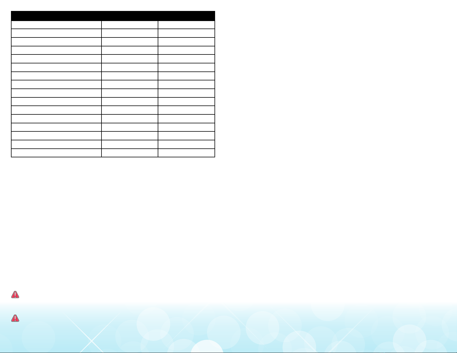
3-STAGE RO SYSTEM – MODEL AQ-RO-BASE
U.S. Metric
Membrane Production135 gpd 132 lpd
Membrane TDS Reduction195% minimum 95% minimum
System Production213.32 gpd 50.4 lpd
TDS Reduction296.3%+ average 96.3%+ average
Maximum TDS 1000 ppm 1000 ppm
Maximum water hardness @ 6.9pH 10 gpg 2.64 gpL
Maximum Chlorine in water 3.0 ppm 3.0 ppm
Supply water pH limits 4-10 4-10
Drain (reject water) Flow 3-5 x product flow 3-5 x product flow
Empty Storage Tank Precharge 5-7 psi air 35-48 kPa air
Storage Tank Capacity23.2 gallons 12.11 liters
Supply water pressure limits 40-100 psi 275-689 kPa
Supply water temperature limit 40-100 F 5-37 C
Eciency317.91% 17.91%
Recovery429.43% 29.43%
Specications – Qualied System Performance
Because the performance of a Reverse Osmosis Membrane is highly dependent upon pressure,
temperature and TDS, the following should be used for comparison purposes only.
1 Industry standards measure RO Membranes performance with no back pressure on the
product water, at 60 psig (414kPa) and 77°F (25°C). Further conditions on the above are 250
ppm TDS and a 30.6% recovery rate. Production rate and TDS reduction figures are for a new
Membrane that has been rinsed for 24 hours. The production rate of a new Membrane can
decrease by 10% per year or more, depending upon the scaling and fouling tendencies of the
Feed Water.
2 Measured at 50 psi, 77°±2°F, and 717 mg/l TDS per NSF/ANSI Standard 58.
3 Eciency rating means the percentage of the influent water to the system that is available
to the user as reverse osmosis treated water. Under operating conditions that approximate
typical daily usage.
4 Recovery rating means the percentage of the influent water to the membrane portion of
the system that is available to the user as reverse osmosis treated water when the system is
operated without a storage tank or when the storage tank is bypassed.
Do not use with water that is microbiologically unsafe or of unknown water quality
without adequate disinfection before or after the system. Systems certified for cyst
reduction may be used on disinfected waters that may contain filterable cysts.
Filter is only to be used with cold water. Systems certified for cyst reduction may be
used on disinfected water that may contain filterable cysts.
Non-potable Water Sources:
Do not attempt to use this product to make safe drinking water from non-potable water
sources. Do not use the system on microbiologically unsafe water, or water of unknown quality
without adequate disinfection before or after the system. This system is certified for cyst
reduction and may be used on disinfected water that may contain filterable cysts.
Arsenic Reduction:
Arsenic (abbreviated As) is found naturally in some well water. Arsenic in water has no color,
taste, or odor. It must be measured by a laboratory test. Public water utilities must have their
water tested for arsenic. You can get the results from your water utility. If you have your own
well, you can have the water tested. The local health department or the state environmental
health agency can provide a list of certified labs. The cost is typically $15 to $30. Information
about arsenic in water can be found on the Internet at the U.S. Environmental Protection
Agency website: www.epa.gov/safewater/arsenic.html.
There are two forms of arsenic: pentavalent arsenic (also called As(V), As(+5), and arsenate)
and trivalent arsenic (also called As(III), As(+3), and arsenite). In well water, arsenic may be
pentavalent, trivalent, or a combination of both. Special sampling procedures are needed for a
lab to determine what type and how much of each type of arsenic is in the water. Check with
the labs in your area to see if they can provide this type of service.
Reverse osmosis (RO) water treatment systems do not remove trivalent arsenic from water very
well. RO systems are very eective at removing pentavalent arsenic. A free chlorine residual will
rapidly convert trivalent arsenic to pentavalent arsenic. Other water treatment chemicals such
as ozone and potassium permanganate will also change trivalent arsenic to pentavalent arsenic.
A combined chlorine residual (also called chloramine) may not convert all the trivalent arsenic.
If you get your water from a public water utility, contact the utility to find out if free chlorine or
combined chlorine is used in the water system.
The AQ-RO-BASE system is designed to remove pentavalent arsenic. It will not convert trivalent
arsenic to pentavalent arsenic. The system was tested in a lab. Under testing conditions, the
system reduced 0.3 mg/L (ppm) pentavalent arsenic to 0.010 mg/L (ppm) (the USEPA standard
for drinking water) or less. The performance of the system may be dierent at your installation.
Have the treated water tested for arsenic to check whether the system is working properly.
The RO component of the AQ-RO-BASE system must be replaced every 1-3 years to ensure that
the system will continue to remove pentavalent arsenic. The component identification and
locations where you can purchase the component are listed in the installation/operation manual.
Nitrate/Nitrite Test Kit:
This system is acceptable for treatment of influent concentration of no more than 27mg/L
nitrate and 3mg/L nitrite in combination measured as N. This system is supplied with a nitrate/
nitrite test kit. Product water should be monitored periodically according to the instructions
provided with the test kit.
Installations in The Commonwealth of Massachusetts:
The Commonwealth of Massachusetts requires installation be performed by a licensed plumber
and do not permit the use of saddle valves. Plumbing code 248—CMR of the Commonwealth of
Massachusetts must be followed in these cases.

Pure Satisfaction
All Aquasana products oer a 90-day satisfaction guarantee. (A 2 year warranty is included,
which covers defects in materials and workmanship.) If for any reason you are not
satisfied with your purchase, simply call us, or the dealer you purchased from, for a Return
Authorization Code and a full refund will be promptly issued upon return. Thank you for
choosing Aquasana!
This filter system is designed and tested for use with genuine Aquasana parts including
replacement filters and all hardware. Use of parts from other manufacturers may result in loss
of contaminant reduction performance, system damage or failure. Use of parts from other
manufacturers will also void your warranty. Please visit aquasana.com for all replacement parts.
Carbon Filters - Change every 6 months*
The carbon filter cartridges are replaceable activated carbon cartridges located in stages 1 and 3.
It is recommended replacing these cartridges at least every 6 months. You may need to replace
more often with high water usage or high sediment level. Replacing these cartridges timely will
protect the RO membrane from high levels of chlorine and/or sediment. As these filters build
up with sediment, you may notice slower water output.
RO Membrane Cartridge - Change every 12 months
The RO membrane is located in stage 2. This membrane reduces the dissolved solids and
organic matter. Most municipally treated water has a 7.0-7.5 pH, in this case you would need to
replace your RO membrane every 12 months. Membrane life depends on pH and supply water
hardness. Higher pH shortens membrane life by causing pin-hole leaks, and would shorten
membrane life. When output and water quality and production rate decrease, it is time to
replace the filter sump.
Important: For the first 36 hours after the initial installation, make sure to periodically inspect
for leaks while the system is running and while it is turned o. If a leak occurs, shut o the
water supply, open up the filter faucet to release pressure from the system & contact Aquasana
Technical Support 866.662.6885.
Flow rate and output are determined by 3 factors:
1Incoming water temperature
2Total dissolved solids (TDS) present in supply water
3Incoming water pressure
Lower temperatures are directly proportional to slower flow rate. All membranes are tested at
77°F. Incoming water temperature should not exceed 100°F. The RO Filter System should also
not be installed in a location susceptible to freezing. The more TDS in the supply water, greater
filter time is required. Incoming TDS should not exceed 1000 ppm. Higher water pressure
enables a higher flow rate. Pressure must be above 40 psi for proper system operation. You may
consider installing a permeate pump or booster pump if your pressure is below 40 psi.
Drain Flow Restrictor
The restrictor is vital for proper operation of the RO membrane cartridge as it keeps water
flowing through the membrane at the proper rate ensuring the water produced is the best
quality. It is recommended the restrictor assembly be periodically inspected to be sure it is
clean and unrestricted. If service is required on the drain flow assembly, disassemble and
reassemble as outlined in Step Six.
*Filter life depends on water usage and water supply quality.

Aquasana, Inc.
6310 Midway Road
Haltom City, Texas 76117
866.662.6885 USA
877.332.7873 Canada
www.aquasana.com AQROBASE_install_20170413
For exclusive deals
facebook.com/aquasana
twitter.com/aquasana
Table of contents
Popular Water System manuals by other brands

Osmio
Osmio Zero IP-II user manual

EINHELL
EINHELL GE-AW 1144 SMART Original operating instructions

BRENNTAG
BRENNTAG HEATSAVR instruction manual

Grundfos
Grundfos IO 50 SQFlex Installation and operating instructions

Omnifilter
Omnifilter OT32 Series E installation instructions

EcoQuest
EcoQuest SpringHouse owner's manual

Zip
Zip HydroTap G4 Installation and operating instructions

salmson
salmson THERMO'CLOCK Installation and starting instructions

AMES
AMES Air Gap 400 Series installation instructions

First Sales
First Sales XTS30 Installation instructions and owner's manual

Trane
Trane Axiom GEH006 manual

AmeriWater
AmeriWater V125DTH Operation & maintenance manual