AQUATECH MINIPACK MP Series User manual

INSTRUCTIONS FOR
0. GENERAL SAFETY INFORMATION, WARNINGS & CAUTIONS
1. INSTALLATION
2.THEUSER
3. SERVICING
4. DISPOSAL
MINIPACK MP SERIES
PRESSURISATION UNITS WITH
MICROPROCESSOR CONTROLS
MODELS: MP31, 32, 71, 72
ISSUE: 6 30/01/2019
Head Office: AGM House, London Rd, Copford, Colchester, Essex CO6 1GT UK
Manchester Office : Unit 10, Wheel Forge Way, Ashburton Road West, Manchester. M17 1EH

PRODUCT IDENTIFICATION
All pressurisation units described in this manual automatically maintain a minimum set pressure, the “Cold Fill”
pressure, in a heating or chilled system by transferring make-up liquid from a breaktank or sealed vessel into the
system.
When the system pressure falls below the required level the Duty pump automatically refills the system until the
pressure is restored. If the Duty Pump fails to maintain the required pressure the Support pump (where fitted) will
operate in addition to the Duty Pump.
Please note that the Serial Number “WNxxxxx” or “SNxxxxx” and model reference will be visible on the unit’s label and
on the back page of the manual supplied with the unit.
Examples of units manufactured by Aquatech Pressmain are shown below: -
Please note: it is also possible for the pump/controls/tanks to have been sold as a separate item, in which case the
O&M manual and CE declaration may only be applicable in part.
Model number examples: -
MiniPack MPxx-B MiniPack MPxx-E
Pressurisation unit with Basic controller Pressurisation unit with Enhanced controller
MP - MiniPack MP
3 max 3.0Bar cold fill pressure
7 max 7.0Bar cold fill pressure
1 1 pump
2 2 pump
B Basic MPC controller
E Enhanced 2020+ controller
e.g. MP31-B = max 3.0Bar cold fill pressure with 1pump and Basic MPC controller.
A “standard/basic” –B pressurisation unit controller has a 2 digit
display: -
An “Enhanced” –E controller with BMS volt free relays has
a 2 line by 20 or 24 character display: -
2.3
PRESSURE SYSTEM IS O.K.
Pressure 2.3 bar

MINIPACK
X:/Aquatech-Pressmain Instruction manuals/current/MINIPACK
3
CONTENTS
0.0 GENERAL SAFETY INFORMATION .................................. 4
0.1
WARNINGS .........................................................................................................................5
0.2
CAUTIONS FOR INSTALLATION...............................................................................5
0.3
CAUTIONS FOR OPERATION/USER .......................................................................7
0.4
CAUTIONS FOR MAINTENANCE .............................................................................7
1. INSTALLATION INSTRUCTIONS......................................................................... 8
1.1
GENERAL...................................................................................................................................................8
1.2
ADDITIONAL WARNINGS & CAUTIONS....................................................................................8
1.3
PROCEDURE ...........................................................................................................................................8
1.3.1
LOCATION .....................................................................................................................................8
1.3.2
FIXING..............................................................................................................................................8
1.3.3
PIPEWORK.....................................................................................................................................9
1.3.4
EXPANSION, CONTROL and HYDRAULIC ACCUMULATOR VESSELS........... 11
1.3.5
IDENTIFYING MiniPack “Standard/Basic” -B or “Enhanced” -E UNITS..............12
1.3.6
ELECTRICAL ...............................................................................................................................12
2. USER INSTRUCTIONS ...........................................................................................14
2.1
CUSTOMER ASSURANCE...............................................................................................................14
2.2
COMMISSIONING.............................................................................................................................. 15
2.3
OPERATING INSTRUCTIONS .......................................................................................................15
2.3.1
ADDITIONAL CAUTIONS..................................................................................................... 15
2.3.2
NORMAL OPERATION..........................................................................................................15
2.3.3
STANDARD/BASIC “-B” CONTROLLER OPERATION..............................................15
2.3.4
ENHANCED “-E” CONTROLLER OPERATION ............................................................ 16
2.3.5
STANDARD/BASIC CONTROLLER SYSTEM WARNINGS & ALARMS.............. 18
2.3.6
ENHANCED CONTROLLER SYSTEM WARNINGS....................................................18
2.3.7
ENHANCED CONTROLLER SYSTEM ALARMS...........................................................19
REMOTE SIGNALS ON ENHANCED MODELS ONLY............................................ 20
RESETTING PARAMETERS................................................................................................20
SERVICING REMINDER......................................................................................................20
2.4
MAINTENANCE INSTRUCTIONS................................................................................................ 20
2.4.1.
ADDITIONAL CAUTIONS..................................................................................................... 20
2.4.2
PROCEDURE.............................................................................................................................. 20
3. SERVICING ................................................................................................................21
MINIPACK
X:/Aquatech-Pressmain Instruction manuals/current/MINIPACK
4
3.1
MAINTENANCE AND CARE OF YOUR EQUIPMENT.........................................................21
3.2
LEGAL REQUIREMENTS.................................................................................................................. 21
3.3
SERVICE CONTACTS ........................................................................................................................21
4. DISPOSAL ..................................................................................................................21
EC DECLARATION OF CONFORMITY ....................................................................22
OPERATING PARAMETERS ........................................................................................22
0.0 GENERAL SAFETY INFORMATION
These instructions are intended for the installer/operator/user/maintenance of this equipment and
must be kept with the equipment, for the life of the equipment and made available to all persons. Please
read GENERAL SAFETY INFORMATION 0.0, WARNINGS 0.1 and CAUTIONS 0.2, 0.3 & 0.4 before
doing anything else, and then follow them carefully.
The unit must only be installed/operated/used/maintained by a competent person; A competent person
is someone who is technically competent and familiar with safety practices and the hazards involved.
Hydraulic Accumulators/Expansion Vessels installed as part of/in conjunction with this equipment, with
Pressure x Volume above 250 Bar-litres, require regular formal inspection by a competent person. This is
a Legal Requirement under the “Pressure Systems Safety Regulations” (PSSR) and the Owner/User
should be made aware of their responsibility for this. (see section 3. Servicing).
Failure to install/operate/use/maintain the equipment as recommended below could cause damage to
the equipment any anything subsequently connected to it, and invalidate the warranty provided by
AquaTech-Pressmain to the buyer.
Any damage caused to the equipment by misapplication, mishandling or misuse could lead to risk of
Electrocution, Burns, Fire, Flooding or injury to people or property dependent upon the circumstances
involved.
This equipment contains moving/rotating parts that must remain guarded. Removal of or missing
guards could lead to serious personal injury.
This equipment automatically restarts after a power interruption.
We accept no responsibility or liability for any consequences or damage/losses due to misapplication,
mishandling or misuse of the equipment.
It should be noted that the assembly of pressure equipment on site under the responsibility of the user
(or his representative) is not subject to the Pressure Equipment Directive 97/23/EC. (National
legislation covering assembly on site will apply)
The latest version of this instruction manual with up to date safety information can be downloaded
from our website at www.aquatechpressmain.co.uk
MINIPACK
X:/Aquatech-Pressmain Instruction manuals/current/MINIPACK
5
0.1 WARNINGS
0.1.1 Do not touch any live parts for at least 5 minutes after switching off the electricity supply. Failure to
observe this will constitute a severe Electric shock and/or Burns hazard and may be lethal.
0.1.2 The equipment is only suitable for earth referenced supplies and must be permanently earthed to avoid
Electric shock hazard.
0.1.3 With equipment isolator OFF, mains voltage may still be present from BMS system. This constitutes an
Electric shock hazard.
0.1.4 Emergency stop button does not remove dangerous voltages from control panel/pump motor
assemblies. This constitutes an Electric shock hazard.
0.1.5 Metal parts (e.g. heat sinks) may reach temperatures of 90 degrees centigrade and will constitute a Burns
hazard.
0.1.6 Some equipment is designed to operate with liquid temperatures up to 150 degrees centigrade and will
constitute a Burns/scalding hazard.
0.1.7 The equipment must not be pressurised beyond the maximum working pressure as stated on
pumps/pipework/vessels/control panel otherwise serious mechanical damage/destruction could occur
causing injury to people or property.
0.1.8 The equipment must not be heated/chilled beyond the maximum/minimum working temperature as
stated on pumps/pipework/vessels/control panel otherwise serious mechanical damage/destruction
could occur causing injury to people or property.
0.1.9 Any damage to equipment, pumpset, vessels, pipework or system components caused by misapplication,
mishandling or misuse could lead to Electric shock hazard, Burns hazard, Fire hazard, Flooding hazard or
cause injury to people or property.
0.1.10 This equipment may contain moving/rotating parts that must remain guarded. Removal of or missing
guards could lead to serious personal injury.
0.1.11 Pressure vessels must never be disassembled whilst in use, they contain high pressure air/gas charge
which could cause injury to people or property.
0.1.12 Pump motors with lifting eyes; the lifting eyes are only suitable for lifting motors NOT the entire pump
assembly. This could cause injury to people or property.
0.1.13 Ensure the base/foundation/plinth/wall to which the equipment is to be attached is sufficiently strong
enough to carry the entire mass of the equipment including the water that it will contain under worst-
case fault conditions. E.g. fully saturated pressure vessel with no air charge, break tank full to
overflowing, etc. Failure to observe this could cause serious mechanical damage/destruction resulting in
injury to people or property.
0.1.14 This equipment contains a fluid which may under certain circumstances leak/drip/spray fluid (e.g.
servicing, repair or malfunction). Ensure any fluid discharge will not cause damage to the surroundings by
taking appropriate action. E.g. install in a place that will not be damaged by leakage or install in a bunded
area with adequate drainage.
0.2 CAUTIONS FOR INSTALLATION
0.2.1 READ GENERAL SAFETY INFORMATION 0.0, WARNINGS 0.1 and CAUTIONS 0.2, 0.3 & 0.4
0.2.2 The unit should only be installed/operated by a competent person; A competent person is someone who is
technically competent and familiar with safety practices and the hazards involved.
0.2.3 Do not lift the pumpset by pipework. Lift the pumpset by the container pallet using a pallet/forklift or crane
by passing strops underneath the skid using a spreader bar. Failure to utilise these facilities will result in
damage to the pumpset.
0.2.4 Store in a dry place to avoid damp conditions deteriorating the equipment.
0.2.5 Protect against dirt, damage and frost. It is absolutely essential that no foreign matter such as pipe thread
swarf, welding slag, grit or stones are allowed to enter the set. Debris of this type can cause severe damage
to the mechanical seals, diaphragms and impeller. Frost/freezing will damage pumps/pipework and control
panel components.
0.2.6 The equipment is only suitable for installation in a clean, dust free indoor environment, with adequate
protection from heat and frost, and sufficient ventilation to ensure cooling of the motors. Ambient air

MINIPACK
X:/Aquatech-Pressmain Instruction manuals/current/MINIPACK 6
temperature should be between 5 and 40 degrees centigrade, non-condensating. Operation outside of
these conditions could seriously damage the equipment.
0.2.7 If the equipment were to be stored or taken out of service for a period of time (e.g. 1 week or more), then
we would recommend draining the equipment of all water/liquid (with due regard to any local regulations)
to prevent frost damage to components. When restarting is required we would recommend commissioning
by our authorised service agent.
0.2.8 Ensure the base/foundation/plinth/wall to which the equipment is to be attached has sufficient mass
compared to the equipment, in order to avoid noise/vibration transmission. E.g. the mass of the base should
be at least five times the mass of the equipment.
0.2.9 Ensure the electrical supply is the correct voltage, current, frequency and type for the equipment supplied
and that suitable circuit protection equipment is installed in the supply. Incorrect electrical installation
could be an electric shock/burns/fire hazard.
0.2.10 When accessing the control panel to make electrical connections adopt anti-static procedures e.g. wear
anti-static earthed wristband, to avoid risk of damaging the controller.
0.2.11 All products that are packaged to include Pressure vessel(s)/Hydraulic Accumulator(s)/Expansion Vessel(s)
are classed as “Assemblies” under the Pressure Equipment Directive (PED). Where units are despatched
with “Loose” vessel(s) for assembly on site it is absolutely essential that they be installed as detailed in the
instructions using the fittings provided where appropriate. Failure to observe this will nullify compliance
with the PED and may present a safety hazard. Your warranty may also be affected.
0.2.12 Where Hydraulic Accumulator(s)/Expansion Vessel(s) are supplied as a loose item, they must be
installed/connected correctly before operating the equipment, otherwise serious damage from over-
pressure/pump overheating could occur.
0.2.13 Do not operate this equipment/pumpset prior to commissioning (section 2.2) This could cause irreparable
damage to equipment/pumpset/pipework/system components.
0.2.14 Isolate the equipment/pumpset before pressure testing system. Excess pressure could irreparably damage
the pressure transducer, pressure switches (where fitted) and the diaphragms of pressure vessel/hydraulic
accumulators.
0.2.15 It is the installers’ responsibility to ensure subsequent pipework etc can accept the pressures generated by
the equipment/pumpset and to install an overpressure safety device into the system with due respect to
the suction pressure present on the pumpset, the pump closed valve pressure stated on the pump, the
maximum working pressure stated on any of the attached pressure vessels and any other device connected
to the system e.g. boilers, calorifiers etc.
0.2.16 When chlorination of the system is carried out, ensure that any residual chlorine is removed by thorough
flushing as detailed in the HSE approved code of practice L8, to avoid damaging the equipment/pumpset.
The normal level of chlorination is up to 2 parts per million (ppm), but shock dosing for sterilization
purposes, at 25-50 ppm for 24-48 hours is acceptable as long as all chlorine is removed once the process is
complete. Chlorination beyond these limits could seriously damage pumpset components and WILL NOT
be covered by the warranty.
0.2.17 The installer/user is responsible for the installation of the correct earthing and protection according to
valid national and local standards. All operations must be carried out by a suitably qualified person.
0.2.18 The equipment is only suitable for earth referenced supplies and must be permanently earthed to avoid
electric shock hazard.
0.2.19 The equipment must be permanently earthed with appropriate sized Earthing.
0.2.20 Equipment containing variable speed drives/motors has high earth leakage current >3.5mA and will require
additional earth bonding whereby a single conductor of increased size or duplicate earth conductors must
be provided.
0.2.21 Never perform high voltage resistance tests on control panels, variable speed drives/motors without first
disconnecting the panel/drive/motor from the circuit being tested as this will damage the built in electronic
components.
0.2.22 Metal parts (e.g. heat sinks) may reach temperatures of 90 degrees centigrade.
0.2.23 EMC - With respect to BS EN61000-3-2 this equipment is defined as ‘professional equipment’ and
therefore the installer/user may need to seek permission from the supply utility to connect this equipment
to the public low voltage mains supply.
0.2.24 It is very strongly advised that the system is pre-filled prior to commissioning. Use of the “Pressurisation
unit” for filling the system pipework, may take considerable time, and in some cases may invalidate the
equipment warranty.
0.2.25 Where “Expansion vessels” are used on LTHW heating system pressurisation units, the temperature of the
fluid returning to the vessels should not exceed 70 degrees Centigrade as this could damage the vessel
diaphragm. Where the temperature exceeds 70C an intermediate cooling vessel should be fitted.
0.2.26 For MTHW and HTHW pressurisation units use a Nitrogen vessel suitable for the system conditions.
Please contact AquaTech-Pressmain for further information.
MINIPACK
X:/Aquatech-Pressmain Instruction manuals/current/MINIPACK
7
0.2.27 Do not use the “Pressurisation unit” for dosing the system with chemicals. Only allow clean cold water into
the break tank. Anything other than clean cold water could damage the pumps/pipework components.
0.2.28 Drain cocks/valves and air bleed screws must not be left open as this could cause flooding.
0.3 CAUTIONS FOR OPERATION/USER
0.3.1 READ GENERAL SAFETY INFORMATION 0.0, WARNINGS 0.1 and CAUTIONS 0.2, 0.3 & 0.4
0.3.2 The unit should only be operated/used by a competent person; A competent person is someone who is
technically competent and familiar with safety practices and the hazards involved.
0.3.3 The Owner/User of this equipment has a Legal Responsibility to ensure that it is subject to regular formal
inspections. See Section 3. Servicing, for details.
0.3.4 Where Hydraulic Accumulator(s)/Expansion Vessel(s) are supplied as a loose item, they must be
installed/connected correctly before operating the equipment, otherwise serious damage from over-
pressure could occur.
0.3.5 The set must not be run until commissioned by an authorised AquaTech-Pressmain agent, this could
irreparably damage the pump set and/or system components/pipework connected to it.
0.3.6 The pumpset should be left switched ON with the pumps switched to AUTO for normal operation.
0.3.7 The pumpset should not be left in “Hand” operation for more than 1 minute. This could lead to severe
damage of pumpset components and/or pipework system from over-pressure and/or overheating.
0.3.8 Ensure pumpset has an adequate water supply at all times to prevent dry running causing pump seal
damage and water leakage.
0.3.9 Do no attempt to start pumps without liquid in volutes (pumps must be fully primed); mechanical seals must
have a film of liquid between faces for proper operation and to prevent damage.
0.3.10 Portable telephones or other electro-magnetic equipment must not be used near the set to avoid
corruption of program and unpredictable operation of unit.
0.3.11 For Pressurisation units utilising Nitrogen Vessels (generally HTHW units) ensure there is an adequate
supply of Nitrogen at all times to avoid mis-operation of the equipment.
0.4 CAUTIONS FOR MAINTENANCE
0.4.1 READ GENERAL SAFETY INFORMATION 0.0, WARNINGS 0.1 and CAUTIONS 0.2, 0.3 & 0.4
0.4.2 The unit should only be operated/maintained by a competent person; A competent person is someone who is
technically competent and familiar with safety practices and the hazards involved.
0.4.3 Where the set is fitted with Building Management Services (BMS) interconnections, notify the appropriate
persons before switching OFF for maintenance or adjustments, to avoid unnecessary alarm conditions
occurring. WARNING: With pumpset isolator OFF, mains voltage may still be present from BMS system.
This constitutes an Electric shock hazard.
0.4.4 To prevent seizing, pumpsets must not be left unused for long periods (e.g. 1 week).
0.4.5 Do not vent air from air valves on vessels. These are for adjustment of pre-set cushion pressures. If wrongly
adjusted this will lead to incorrect operation of the pumpset and possible damage to pumps, pipework and
system components from overheating and over-pressure.
0.4.6 Switch OFF pumpset before accessing pumps and/or control panel.

MINIPACK
X:/Aquatech-Pressmain Instruction manuals/current/MINIPACK 8
1. INSTALLATION INSTRUCTIONS
1.1 GENERAL
These instructions are intended for the installer of this pressurisation unit. Please follow them carefully.
The unit should only be installed by a competent person; A competent person is someone who is technically competent and
familiar with safety practices and the hazards involved.
It should be noted that the assembly of pressure equipment on site under the responsibility of the user (or his
representative) is not subject to the Pressure Equipment Directive 97/23/EC. (National legislation covering assembly
on site will apply).
Failure to install the equipment as recommended below could invalidate the warranty provided by AquaTech-
Pressmain to the purchaser.
1.2 ADDITIONAL WARNINGS & CAUTIONS
1.2.1 READ GENERAL SAFETY INFORMATION 0.0, WARNINGS 0.1 and CAUTIONS 0.2, 0.3 & 0.4
1.3 PROCEDURE
1.3.1 LOCATION
The pressurisation unit should be connected to the underside of the return header on the suction side of the
circulating pump, but not within any influences from the circulating pump, and for a heating system, at the
point of lowest temperature i.e. before the boiler.
If the equipment is to be installed in an unheated room, ensure that there is adequate frost protection. On a
heating system do not lag any expansion vessel or its connection to the system. This can result in damage
occurring.
The location of the equipment should have adequate drainage, bunding or other appropriate measures to
protect assets and the building fabric in the event of leakage or water spillage. Failure to provide such
measures may result in water damage to property and assets.
Ensure that location for the equipment provides adequate clear space to accommodate unit with reasonable
access to all parts; AquaTech-Pressmain recommend a minimum distance of 500mm. There must be
sufficient room to:-
fully open control panel door & withdraw diaphragms from vessels,
Should any of these location conditions not be satisfied AquaTech-Pressmain reserve the right to charge
labour on any warranty work required on the pumpset.
1.3.2 FIXING
Lugs are provided for wall fixing on the back of the panel (see fig. 1.1)
Fig 1.1
MINIPACK
X:/Aquatech-Pressmain Instruction manuals/current/MINIPACK
9
1.3.3 PIPEWORK
1.3.3.1 Mains Water Supply
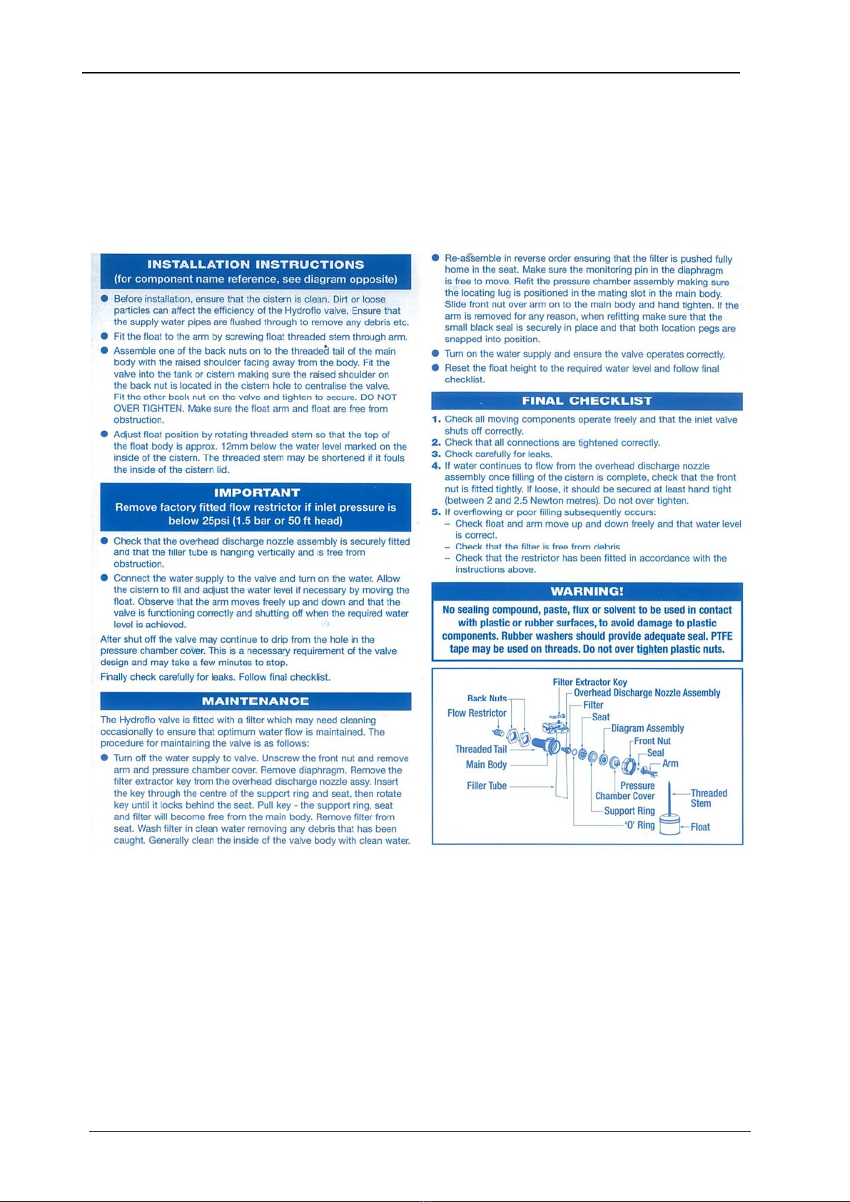
i. Fit an isolating valve in the supply to enable the unit to be isolated from the supply for maintenance. Make
sure the float valve restrictor is fitted if the mains water inlet pressure exceeds 1.5 Bar. If the mains
water inlet pressure is less than 1.5 Bar, the restrictor should not be fitted.
ii. Float Valve Instructions as follows: -
iii. For category 4 & 5 installations remove the filler tube to comply with local water regulations.
1.3.3.2 System Connection
i. The unit must be connected with any expansion vessels and cooling vessels, to the underside of the return
header on the suction side of the circulating pumps and boiler/chiller (see Location 1.3.1)
ii. The system connection on the pressurisation unit is 15mm compression/1/2” BSP at the side of the cabinet.
An isolating valve must be fitted to isolate the unit from the system.
iv. All hydraulic accumulators and expansion vessels fitted to the system must have isolating and drain off
valves to enable them to be serviced.
v. All hydraulic accumulators and expansion vessels fitted to the system must have connecting pipework that
is removable to give access for replacing vessel diaphragm, and must be large enough to avoid friction
losses.

MINIPACK
X:/Aquatech-Pressmain Instruction manuals/current/MINIPACK 10
1.3.3.3 Overflow
i. An overflow warning pipe is fitted to the side of the panel. This can be extended as required using 22mm
OD pipe which will fit inside the supplied overflow.
Pressure
Transducer
Level Sensor Mains Water Break Tank
15mm Float Valve
15mm Incoming
Mains Supply
Microprocessor Controller System connection
on suction side of
Circulating Pumps
Sytem filling device
e.g. quick fill loop,
(check local water
regulations)
Drain Cock
Isolating Valve
Pressurisation
pumps
IMPORTANT
Make connection to the
UNDERSIDE of system
pipework
"AquaTank"
diaphragm
expansion
vessel
CONTROLLER
MiniPack Pressurisation Unit Pipework supplied and fitted by installer
Isolating Valve
Isolating
Valve
System
connection
Fig 1.2: Typical Pipework Layout.

MINIPACK
X:/Aquatech-Pressmain Instruction manuals/current/MINIPACK
11
1.3.4 EXPANSION, CONTROL and HYDRAULIC ACCUMULATOR VESSELS
D
H
DN
60 - 500 Litre
Fig 1.3 typical expansion vessel dimensions
Type (stockcode MTH-) 300060 300100 300200 300300 300500 700100 700200 700300 700500
Nominal Content –litres 60 100 200 300 500 100 200 300 500
D mm 409 480 634 634 740 450 485 485 600
H mm 740 840 980 1280 1485 850 1400 1965 2065
Water Connection DN BSP 1” 1” 1 ¼” 1 ¼” 1 ¼” 1” 1 ½” 1 ½” 1 ½”
Weight Kg 25 32 50 55 85 18 49 60 90
Max. working Pressure-bar 10 10 10 10 10 10 10 10 10
Max. Continuous
temperature deg. C
70 70 70 70 70 100 100 100 100
All vessels must be securely mounted to prevent any movement from imposing strain on the attached pipework.
Vessels of 60 litres capacity or greater MUST be mounted vertically on the integral legs with water connection
lowermost.
Set up the vessel so the air charge filling valve (top) and the diaphragm (bottom on 70°C vessels, top on 100°C vessels)
are accessible for future maintenance. All vessels must have isolating and drain off valves fitted to enable them to be
serviced. The connecting pipework should be removable to give access for replacing the diaphragm and should be the
same size as the vessel connection to minimise friction losses. Note: if using a flexible hose it must be suitable for the
temperature of the system.
Fig. 1.4a & b Isolation valve on system pipework & Flexible hose with drain cock on vessel
Set the air cushion pre-charge pressure (see 2.4.2 Maintenance Procedure for details) to the correct level, dependent
on the application required for the vessel. Refer to the Operating parameters at the back of this manual or Aquatech-
Pressmain for advice.
Caution: If the air cushion pre-charge pressure required exceeds 4.0 Bar then you must follow the procedure shown in
section 2.4 to avoid damaging/rupture of the internal diaphragm and consequences of. E.g. High and/or low pressure
problems, unstable pump operation.

MINIPACK
X:/Aquatech-Pressmain Instruction manuals/current/MINIPACK
12
1.3.5 IDENTIFYING MiniPack “Standard/Basic” -B or “Enhanced” -E UNITS
1.3.5.1 The control panel fascia will state the “Model” and the “Serial Number” e.g. WN12345 or SN0654321. In
addition to this: -
1.3.5.2 A “standard/basic” –B pressurisation unit controller has a 2 digit
display:-
1.3.5.3 An “Enhanced” –E controller with BMS volt free relays has
a 2 line by 20 or 24 character display: -
1.3.6 ELECTRICAL
READ GENERAL SAFETY INFORMATION 0.0, WARNINGS 0.1 and CAUTIONS 0.2, 0.3 & 0.4
1.3.6.1 All wiring must comply with the latest addition of local wiring Regulations.
1.3.6.2 Wear anti-static wrist strap at all times to avoid static discharge causing problems with the built in
electronic program.
1.3.6.3 Connect incoming electrical mains supply to isolating switch & Earth stud in panel (see fig.1.6). Ensure
voltages and frequency indicated on the motor nameplates and wiring diagrams correspond with supply
mains data and that the supply fuse ratings are correct for the total current rating of the equipment.
Refer to wiring diagram supplied with the unit or AquaTech-Pressmain.
1.3.6.4 For standard controller units: Connect boiler/chiller to plug/socket terminal on pcb card in series with the
boiler/chiller control circuits so that in the event of a fault condition occurring the boiler/chillers shut
down and remain inoperative until the fault condition is rectified. (See fig 1.6b). Boiler relay is energised
for normal condition and releases to a high or low-pressure alarm fault condition.
1.3.6.5 For Enhanced controller units: Make any BMS connections required to terminals A-Z on Interface pcb
card inside control panel. Connect boiler/chiller terminals nos. X,Y,Z on interface card in series with the
boiler/chiller control circuits so that in the event of a fault condition occurring the boiler/chillers shut
down and remain inoperative until the fault condition is rectified. (See fig 1.7). Boiler relay is energised for
normal condition and releases to a high or low-pressure alarm fault condition.
1.3.6.5 Complete any required earth bonding.
Note: To aid access to the controls, switch off the power, remove outer cover, undo the two control shelf retaining
screws (Fig 1.5a), the control shelf will now hinge forward (Fig 1.5b). When complete reverse the above sequence
ensuring the two control shelf retaining screws are refitted correctly to ensure the keypad & display line up with the
holes in the outer cover. DO NOT trap any wires!
Fig 1.5a Control shelf retaining screws. Fig 1.5b Control shelf hinged down.
2.3
PRESSURE SYSTEM IS O.K.
Pressure 2.3 bar
MINIPACK
X:/Aquatech-Pressmain Instruction manuals/current/MINIPACK 13
P1P2 N NEEENL
+10
I/P E
E
NC
NO C
(2)
(1)
(3)
Set Point adjust
Boiler/Chiller
volt free relay
240VAC 1A max.
High pressure
adjust
Delivery Pipework
PT1
OL1
3
2
OL2
P1
PCB1
MPC-Pu Controller
G/Y
L1
N
E
3
G/Y
2
1
3 core
screened cable
292 Pressure
Transducer
Supply
240VAC
2A 50Hz
(black)
(black) N
(black) L
Break
Tank
LWP1
Low Water
Probes
(G/Y)
(black)
(G/Y)
(G/Y)
P2
N12
(G/Y)
(black) P1
(black) N11
(G/Y)
N1
L11
(G/Y)
P1
N11
P2
N12
P11
P21
1
(G/Y)
0
0
1
(Black)
(Black)
(G/Y)
PCB2
E
N
L
E
IS1
8.8.
Typical Boiler Interrupt Circuit (wiring by others)
Control relay
Control thermostat
N
SUPPLY
Boiler/burner controls
no
Pressure fault
ncc
21 2220
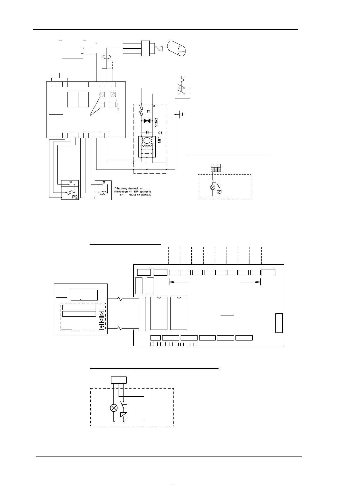
Fig 1.6a Typical standard –B controller Wiring Diagram Fig 1.6b Typical Boiler wiring (by
others)
PCB1
PCB2
PCB3
O
Keypad
2020Plus controller
Pump 2 Auto/Off/Hand
Pump 1 Auto/Off/Hand
Display
Pressure fault
nocnc
Boiler/burner controls
ZYX
SUPPLY
N
Control thermostat
Control relay
Typical Boiler Interrupt Circuit (wiring by others)
IP2
4-Channel
Level
Sensing
Module
IP1
4 Channel
Analogue
Input
Module
Boiler
Cut-out
Common
Warning
Transducer
Failed
Pump
Failed
Pump Starts
Excessive
High/Low
Water
Low
Pressure
High
Pressure
F2F1
Pump2Pump1
T1A T1A
BMS volt free outputs
max 240VAC 50Hz 1.5A
no
c
nc
no
c
nc
no
c
nc
no
c
nc
no
c
nc
no
c
nc
no
c
nc
no
c
nc
13
12
11
10
9
3
2
1
8
7
6
5
4
to Controller
on door
24VAC
12VAC
0V
C
BA
Z
YXWV
U
TS
R
P
ONM
LKJ
HGF
E
D
B1
B2
B3
A1
A2
A3
2ETM40E Mothercard
Typical wiring connections
Fig 1.7 Typical Enhanced -E controller Wiring Diagram

MINIPACK
X:/Aquatech-Pressmain Instruction manuals/current/MINIPACK 14
2. USER INSTRUCTIONS
2.1 CUSTOMER ASSURANCE
AQUATECH PRESSMAIN ASSURE YOU THAT IF ANY PART OF THIS EQUIPMENT BECOMES
DEFECTIVE DUE TO FAULTY MANUFACTURE OR MATERIALS WITHIN 24 MONTHS
FROM THE DATE OF INVOICE THE PART WILL BE REPAIRED OR REPLACED.
The only conditions are: -
The equipment must have been installed, commissioned, operated and maintained as recommended by
AquaTech-Pressmain.
The equipment must not have been neglected, misused, modified, or used for any other purpose than its original
application.
The commissioning should be carried out within 6 months of the date of invoice by an authorised AquaTech-
Pressmain agent
This Assurance does not apply to those items not supplied by us or to defects arising from parts not made or
approved by AquaTech-Pressmain. The individual manufacturers own policies for dealing with defects will apply.
Any part repaired or replaced under these Assurances will be covered for the balance of the appropriate
Assurance period.
If we have any disagreement about these Assurances which we are unable to resolve we will both abide by the
decision of an agreed Arbitrator or, if we are unable to agree, one appointed by the Building and Engineering
Services Association (B & ES) Arbitration Scheme Rules.
These Assurances are in addition to, and do not detract from, the contractual rights you have under Statute or at
common law.
Failure to comply with the installation, commissioning and maintenance procedures will invalidate the warranty.
For full details please see the AquaTech-Pressmain "CONDITIONS OF SALE"

MINIPACK
X:/Aquatech-Pressmain Instruction manuals/current/MINIPACK
15
2.2 COMMISSIONING
Whilst this set has been tested in the factory to the required settings (detailed in operating parameters at the back of
instruction manual), it is impossible to simulate the actual on-site conditions, especially if they are unusual. Also, the
settings may have been disturbed since leaving the factory.
Therefore we strongly recommend the set is commissioned by our authorised agent who will prepare the set, make
any necessary adjustments and leave the set in operational order.
Commissioning is a requirement to validate the Warranty (see Customer Assurance)
Prior to requesting an engineer to attend the site for commissioning, the client must ensure that;
the equipment has been correctly installed;
a written scheme of examination has been obtained where required under the Pressure Systems Safety
Regulations;
an adequate water supply and permanent electricity supply are available;
the equipment and pipework in the building being served by the pressurisation unit is capable of accepting
the generated pressures.
2.3 OPERATING INSTRUCTIONS
This unit is used for maintaining the pressure in pressurised heating or chilled systems with a volume up to 10,000
litres at 82ºC or boiler power up to 1000kW.
READ GENERAL SAFETY INFORMATION 0.0, WARNINGS 0.1 and CAUTIONS 0.2, 0.3 & 0.4
2.3.1 ADDITIONAL CAUTIONS
2.3.1.1 Isolate the pressurisation unit from the system before draining or modifying the system. If the unit is
drained it must be recommissioned.
2.3.2 NORMAL OPERATION
The pressurisation unit automatically maintains a minimum set pressure, the “Cold Fill” pressure, in a heating or chilled
system by transferring make-up liquid from a breaktank or sealed vessel into the system. When the system pressure
falls below the required level the Duty pump automatically refills the system until the pressure is restored. If the Duty
Pump fails to maintain the required pressure the Support pump (where fitted) will operate in addition to the Duty
Pump.
2.3.3 STANDARD/BASIC “-B” CONTROLLER OPERATION
The control is by AquaTech-Pressmain “MPC-Pu” Microprocessor, with a 2 character display on the control panel,
showing the current system pressure in Bar.
To spread the wear evenly between the pumps the Duty Pump alternates each time both pumps stop (where two
pumps are fitted).
If there is an interruption in the electrical supply the unit will restart on restoration of the supply.
The unit must be left switched ON with the system connection valve OPEN.
When switched on the display shows the controller type
Then self checks stating the firmware ref. eg.
Followed by the system pressure in bar
(Screens shown are examples only)
1
2
2.3
P
u

MINIPACK
X:/Aquatech-Pressmain Instruction manuals/current/MINIPACK
16
2.3.4 ENHANCED “-E” CONTROLLER OPERATION
The control is by AquaTech-Pressmain “2020Plus” Microprocessor, with a 2-line by 20 or 24 character display on the
control panel, showing the current system pressure and status.
When switched on the display shows,
then self-checks, flashing all LED lights on keypad,
and identifies configuration for pump operation
(e.g. “MP” pressurisation unit)
followed by the system status and pressure
For “normal” operation, all Hand/Off/Auto switches should be left in “Auto”, all isolating valves should be left open, all
hydraulic accumulator/expansion vessel isolating valves should be left open, and drain cock/valves should be left
closed. Should it be necessary to have a situation that is not “normal” operation, then we would strongly recommend
attendance to site by our trained/authorised service personnel. Please contact AquaTech-Pressmain for more details.
Pump Operation
Sealed system pressurisation unit; All Models:
The pressurisation unit automatically maintains a minimum set pressure, the “Cold Fill” pressure, in a heating or chilled
system by transferring make-up liquid from a breaktank, into the system. When the system pressure falls below the
required level the Duty pump automatically refills the system until the pressure is restored. If the Duty Pump fails to
maintain the required pressure the Support pump (where fitted) will operate in addition to the Duty Pump.
Duty Pump Rotation.
To spread the wear evenly across both pumps (where fitted), their sequence is
automatically rotated either by starting the pump that has been idle the longest and/or by timed operation (dependent
upon unit type).
Indicator lights (where fitted) on the fascia show which pump is running.
Automatic Restart (when “manual restart” is set to “not enabled” on 2020 Plus controller)
If there is an interruption to the electrical supply the unit will automatically restart on restoration of the supply.
Pumps will restart at timed intervals.
Manual Restart (when set to “enabled” on 2020 Plus controller)
If there is an interruption to the electrical supply, or there is a low water level condition, the unit will need to be
manually reset on restoration of the supply, or low water level condition, by pressing the “Reset Alarm” key. Pumps
will then restart at timed intervals.
Pressure setting.
The pumpset is set at the default 'duty/cold fill' pressure at the factory. If necessary, the
pressure will be adjusted at commissioning to suit local conditions.
To view the parameters (Enhanced controller only)
Press <SET/VIEW> on the keypad. Then, press the same key 4more times.
Press the <UP> (7) key, to view the next parameter.
Page through the parameters by using the <UP> (7) and <DOWN> (8) keys to view:
Various parameters will be displayed dependent upon unit type. The main parameters that customers are interested in
are shown on the following page.
Date and Time (24 hour clock) not password protected to allow
on site adjustment.
Fault Log (last 30 faults) press <view> to see log followed
by <up> (7) or <down> (8) to view
log.
press <enter> to return
Manual Restart upon power failure not password protected to
AQUATECH 2020Plus V5.01
PRESSMAIN
MP
Time
14/01/15…….22:40:15
Fault Log
PRESSURE SYSTEM IS O.K.
Pressure ………… bar
Manual Restart
Not enabled

MINIPACK
X:/Aquatech-Pressmain Instruction manuals/current/MINIPACK
17
or low water level condition allow user to enable/disable
Pumps 1 & 2 hours run time
Time elapsed since last service service reminder after 6 months
Total run time (power up time) not resetable
Enable service call enable/disable service reminder
Low pressure alarm low pressure alarm. Note: low
pressure approach warning is 0.2
bar more than this value
Low pressure delay time before alarm is initiated.
High pressure high pressure alarm. Note: high
pressure approach warning is 0.2
bar below this value
High pressure delay time before alarm is initiated.
Duty delay to delay duty pump starting to
circulator pump pressure dips
Support delay to delay support pump starting in
normal operation preventing
electrical/pressure dips/surges
Starts in 12 minutes sets frequency of pump starts
warning (system leak detection)
Duty pressure (cold fill) duty pump cut-out/cold fill
pressure. All other pumps are
derived from this value.
Minimum run time for each pump
Pump x run time
000123.4 Hours
Since last service
000987.6 Hours
Total run time
005000.0 Hours
Enable service call
Enabled
Low pressure
0.8 Bar
Low p delay
10 sec
High pressure
3.0 Bar
High p delay
10 sec
Duty delay
0 sec
Support delay
10 sec
Starts/12 mns
8
Duty pressure
1.6 bar
Min run time
3 sec

MINIPACK
X:/Aquatech-Pressmain Instruction manuals/current/MINIPACK 18
2.3.5 STANDARD/BASIC CONTROLLER SYSTEM WARNINGS & ALARMS
Flashing 2 digit display giving type of fault and a boiler/chiller volt free output signal for high or low pressure
condition. Relay energised for normal condition and releases for a high or low pressure alarm fault condition.
Displayed Message Cause Check
L P (Low pressure) system pressure at/below low
pressure setting & delay timer expired
Pressure vessel air charge wrong? Or
water usage exceeds design capacity?
Or pump(s) are tripped or air locked.
LL(Low water Level)
water level below supply tank low
water alarm probe or pipework sensor
dry. (240 second delay on automatic
restart, after restoration of water
level).
Break tank float valve stuck closed?
Or output of pumpset exceeds mains
water supply into break tank? Mains
water interruption to break tank?
H P (High pressure) system pressure at/above high
pressure setting & delay timer expired
Pressure vessel air charge wrong? Or
system water content exceeds design
capacity? Or pump(s) are continuously
running?.
O r (system pressure Over Range)
Pressure sensor output above 9.9 Bar
or pressure sensor not connected
correctly.
Pressure higher than 9.9 Bar? Or
pressure sensor failed? Or pressure
sensor wiring loose?
S P (setpoint point out of range) The setpoint pressure has been set
either below 1.2 Bar or above 9.9 Bar.
Adjust setpoint pressure within
normal range.
No Display 1 Amp control fuse may have blown.
If unit has been switched off for a long
period, a turbine pump (where fitted)
may have seized. Switch off unit, insert
flat blade screwdriver into slot on end
of motor shaft and rotate pump until
free. Replace fuse with T1Ax20mm,
try again.
2.3.6 ENHANCED CONTROLLER SYSTEM WARNINGS
Flashing display giving type of fault and a various volt free output signals on BMS enhanced models. (see wiring
diagram provided with unit to see which volt free signal relays are present. Typical example shown in fig. 1.7).
***** Warning ***** Cause Check
High pressure approach system pressure at high pressure
setting minus 0.2 Bar
Pressure vessel air charge wrong? Or
insufficient expansion capacity?
Low pressure approach system pressure at low pressure
setting plus 0.2 Bar
Pressure vessel air charge wrong? Or
water usage exceeds design capacity?
Pump starts exceeded/is system
leaking?
duty pump starts exceeded “starts in
12 mins” parameter
System pipework is leaking
excessively? Starts parameter set too
low?
Excessive run time/ is system leaking? duty pump continuously running for
12 minutes
System pipework is leaking
excessively?
Commissioning needed Unit has not been commissioned by
authorised service engineer
Have unit commissioned by
authorised service engineer.
Power Up Power interruption started “Power
Up” sequence
Incoming electrical supply
interruption? Or missing phase? Or
loose connections?
Low level delay
A low water level condition has reset,
and a 4 minute delay is now initiated
before normal operation will resume
Check pumps are vented and wait for
the delay time to expire
Manual restart
(when set to enabled)
A power interruption or low water
level has occurred,
Carry out all necessary checks, then
press the “Reset alarm” key on the
micro

MINIPACK
X:/Aquatech-Pressmain Instruction manuals/current/MINIPACK 19
2.3.7 ENHANCED CONTROLLER SYSTEM ALARMS
Flashing display giving type of fault, audible alarm, volt-free output signals on BMS Enhanced models, and action as
described. (see below). (see wiring diagram provided with unit to see which volt free signal relays are present. Typical
example shown in fig. 1.7).
RESET: Alarms are manually muted and reset using the UP (7) or DOWN (8) buttons on the keypad. (Automatic
reset facility can be provided)
***** Alarm ***** Cause Check
Pressure system Fault Check pumps 1 & 2 for a pump-tripped
condition.
Check electrical supply is within tolerance, or
missing phase? Pump seized? motor failed?
Motor thermistor overheated?
High pressure system pressure at/above high
pressure setting & delay timer expired
Pressure vessel air charge wrong? Or insufficient
expansion capacity? Pump(s) left in Hand?
Low pressure system pressure at/below low
pressure setting & delay timer expired
Pressure vessel air charge wrong? Or water
usage exceeds design capacity? Pump(s) switched
Off or Tripped?
Transducer failed
Pressure sensor output above normal
range of pressure sensor or pressure
sensor not connected correctly.
Pressure higher than sensor range? Or pressure
sensor failed? Or pressure sensor wiring loose?
Pump overload fault Pump/Inverter tripped signal present
Check electrical supply is within tolerance, or
missing phase? Pump seized? motor failed?
Motor thermistor overheated?
No water in feed tank
water level below supply tank low
water alarm probe or pipework sensor
dry. (240 second delay on automatic
restart, after restoration of water
level).
Break tank float valve stuck closed? Or output of
pumpset exceeds mains water supply into break
tank? Mains water interruption to break tank?
Pump overheated Pump motor temperature too high. Pump seized? motor failed? Motor thermistor
overheated?
High water level Tank 1 water level above supply tank high
water alarm probe
Break tank float valve wrongly adjusted, stuck
open or letting by? HP restrictor fitted to
F/valve?
Low water level Tank 1
water level below supply tank low
water alarm probe or pipework sensor
dry. (240 second delay on automatic
restart, after restoration of water
level).
Break tank float valve stuck closed? Or output of
pumpset exceeds mains water supply into break
tank? Mains water interruption to break tank?
Other Fault Hardware shutdown Please call AquaTech-Pressmain for advice
No Display 1 Amp control fuse may have blown.
If unit has been switched off for a long period, a
turbine pump (where fitted) may have seized.
Switch off unit, insert flat blade screwdriver into
slot on end of motor shaft and rotate pump until
free. Replace fuse with T1Ax20mm, try again.
If a problem persists contact AQUATECH-PRESSMAIN quoting the serial number WN:_______
or SN:_________ (on control panel fascia)

MINIPACK
X:/Aquatech-Pressmain Instruction manuals/current/MINIPACK
20
REMOTE SIGNALS on Enhanced models only
- volt free contacts in control panel (see fig 1.7) :
High system pressure, Low system pressure, High/Low Water level in break-tank, Excessive pump starts, Pump
tripped/failed, Transducer failed, Common warning, , Boiler/chiller cut-out
RESETTING PARAMETERS
The parameters can be protected from inadvertent alteration by a password security code. The factory default is for
no password protection to be enabled. This can be changed to password protected if required.
Parameters may be reset on site by a user or an Aquatech-Pressmain Service engineer.
SERVICING REMINDER
When routine service is due display gives telephone no. to call
This can be deactivated if required.
If a problem persists contact AQUATECH-PRESSMAIN service department quoting the serial
number WN:_______ (on control panel fascia)
2.4 MAINTENANCE INSTRUCTIONS
2.4.1. ADDITIONAL CAUTIONS
2.4.1.1. READ GENERAL SAFETY INFORMATION 0.0, WARNINGS 0.1 and CAUTIONS 0.2, 0.3 & 0.4
2.4.2 PROCEDURE
Every 6 months the unit should be maintained by authorised AquaTech-Pressmain service agents - see Servicing
(Section 3).
Expansion, Control and Hydro Accumulator vessels
1. Air Charge Pressure.The correct charge pressure provides reliable operation of the system and a prolonged
lifetime of the diaphragm. This should be checked regularly. Caution: If the air cushion pre-charge pressure
required exceeds 4.0 Bar then you must follow the procedure shown below to avoid damaging/rupture of the
internal diaphragm and consequences of. E.g. High and/or low pressure problems, unstable pump operation.
2. To adjust air charge pressure < 4.0Bar: isolate the vessel from the system and release pressure on water side
by opening the drain cock disposing of the water-mix in the appropriate manner. The water inside the bladder
will be pushed back by the air charge pressure. Remove cap on the filling valve, set air charge pressure refilling
using dry air or nitrogen. Screw cap firmly on filling valve. Close the drain cock and slowly open water
connection to the system.
3. To adjust air charge pressure > 4.0Bar: If vessel is already in use then isolate hydraulically, reduce the air
charge to 4.0Bar then evacuate the water side of the vessel followed by evacuation of the air side. With the
vessel empty of water and air, set the air charge pressure (using dry air or nitrogen) to 4.0Bar, bring the water
side pressure up to 5.0Bar and close isolating valve, then add more air until the air side pressure is equal to the
required pre-charge pressure multiplied by 1.2 e.g. for a pre-charge pressure of 6.0Bar after filling vessel with
air to 4.0Bar followed by water to 5.0Bar, fill the air side to 6.0 x 1.2 = 7.2Bar. Screw cap firmly on filling valve
and slowly open isolating valve & water connection to the system.
4. Float Valve Maintenance. See installation instructions section for extract regarding cleaning float valve filter
etc.
LEAVE SET WITH ALL PUMPS SWITCHES IN THE AUTO POSITION,
THE MAINS SUPPLY SWITCHED ON, AND THE SYSTEM CONNECTION OPEN
System O.K./routine service due/
for maintenance call/ AquaTech
Pressmain. 01206 215121
Pressure ……….. bar
This manual suits for next models
4
Table of contents
Other AQUATECH Water Pump manuals


Popular Water Pump manuals by other brands

Lochinvar
Lochinvar ARM3072PAB Specification sheet

Solinst
Solinst 410 operating instructions

Mega
Mega SPV Series Installation & operating instructions

Pentair
Pentair HYPRO 93HPS Series Installation and operation manual

Milwaukee
Milwaukee M18 TP Operator's manual

STA-RITE
STA-RITE DURA-JET 5DJAFB-0001 owner's manual

Kessel
Kessel Aqualift XL Basic Installation and operating manual

Crane
Crane Barnes 8SHDA Installation and operation manual

SPX
SPX Accumulator instruction manual

Pentair Hydromatic
Pentair Hydromatic FG-3100RF Installation and operation manual

Eckerle
Eckerle EE 1200 instruction manual

North Ridge Pumps
North Ridge Pumps RBT Series operating instructions


