Aquatel D110 User manual

MULTI TANK CAPABLE MODEL D110
INSTRUCTION MANUAL
Wireless Level Monitor
Aquatel NZ Ltd
P.O.Box 225 Orewa 0931, New Zealand
www.aquatel.co.nz

–1 –
•Temperature range : -10 to +60°C (14 to 140°F)
•Individually Security coded sets
•Approval : AS/NZS 4268:2003 1:2005
•Housing : ABS Plastic
•Circuit Boards : ROHS compliant
•Radio frequency 920Mhz FHSS & Fixed 860Mhz Eurpoe
DISPLAY UNIT
•External Power Jack (Use Aquatel certified
power pack. Part No. AQPP6)
6V DC
•¼ Wave Whip Antenna
•92mm W x 73mm D x 50mm H
(3 5/8”W x 2 7/8”D x 2”H)
TANK UNIT
•Use on any non-flammable fluid
(water, diesel, septic)
•¼ Wave Whip Antenna
•135mm diameter x 80mm H
(5 3/8”D x 3 1/8”H)
•Detection Range 0.1m to 4m (4”–13’)
300m*
(1,000’)
Multi-Tank Level Monitor
D110

–2 –
The D110 is a versatile product that not only
allows remote monitoring of multiple tanks/
cistern fluid levels, it also allows you to set
high and low level alarms to a height you
wish to be notified at.
The D110 is a Wireless tank/cistern fluid level monitor that is capable of remotely
monitoring up to 6 tanks from the one Display unit. Each D110 system comes with one
Display and a single Tank Unit. To monitor more than one tank/cistern, additional T110
Tank Units can be purchased and paired with your Display Unit. It is recommended
that you fully read this installation manual prior to installing your D110 system.
If you have any questions, please do contact us prior to use.
Main features and benefits:
. Fully wireless remote tank/cistern monitoring
. Easy to read blue backlit LCD display
. Monitor up to 6 tanks from the one Display
. Adjustable air gap allows for mounting in tank/cistern riser
. Adjustable High and Low level alarms
. Non contact to fluid
How it works:
The Tank Unit is mounted on the top surface of the tank or on the inside top surface
of an underground cistern and uses ultrasonic signals to detect the fluid levels inside.
This is then wirelessly transmitted back to the Display Unit to give you up to date fluid
level information. The system will warn you of any triggered High or Low fluid level
alarm via the Display Unit.
. Easy to install and setup

–3 –
Installing Tank Unit
1Choose location for Tank Unit on the top of the tank or cistern, close to an
inspection hatch is best in case you need to adjust the sensor cone.
✔Ideal. Mount within
reach of access hole
For plastic tanks use the supplied screws to attach the Tank Unit to the tank.
For metal tanks first drill 3mm or ¼" holes, and then fasten using the screws.
For concrete tanks drill 6mm or ¼" holes, insert the supplied plastic plugs and then
fasten using the screws. IMPORTANT NOTICE: Do not over tighten screws when
fastening to tank unit to the tank top, as this may cause the housing to split.
8
✘
✘
✘
Antenna should be
mounted on the
opposite side
✘
Transducer is not
pointing at the
surface of the water
500m line of sight
M107
✔
✔✔Water will not enter
antenna hole
✔Transducer is parallel
to water
2Drill a 50mm (2”) hole in tank.
For thick concrete tanks make
a 75mm (3”) hole.
3Measure the depth of
tank to the base (or to the
water outlet). Write this
measurement down.
4
Insert Tank Unit in hole and
rotate so tank antenna is on
the lower side (to prevent
water entering unit). Ensure
that the transducer cone
underneath is pointing
directly at the surface of the
water.
For tanks less than 1500mm (5’) it’s best to deep mount unit in center of tank
Installation
✘Incorrect. Mount unit
away from ribbed walls
to prevent signal
reflection off walls
✔Correct. For buried
tanks mount unit in
center of lid, or on
bracket mounted in riser

– 3 – – 4 –
Setting up Tank Unit
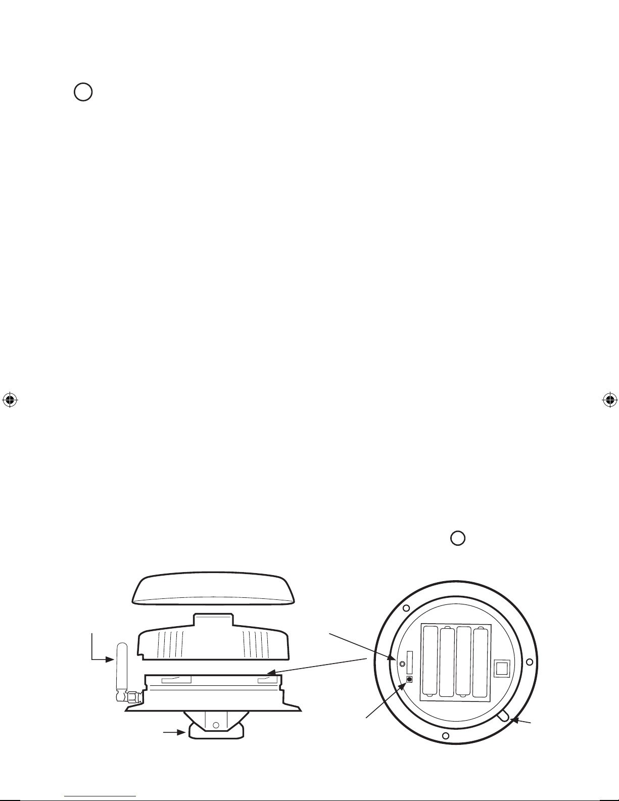
5RemovecapfromTankUnitbyturningcounter-clockwiseandinsertbatteries.
CheckthattheTankUnitispairedwiththeDisplayUnitonceyouhaveitpowered
up.YoucanchecksignalstrengthbetweenunitsontheDisplayUnit,therewillbe
asignalstrengthbargraphmeteratthetoprightoftheLCDscreen,rangingfrom
1to4bars.
Test Mode
WhensettingupyourTankUnit,youcansettheTankUnitintoTestModeviathe
displaysothatitsendsanewreadingevery8seconds.WheninTestMode,theTank
Unit’sTestModeLEDwillbeON(seepicturebelow).WhenoutofTestModetheLED
willbeOFF.TestModecanbeturnedonoroffviathe“Systemsetup”then“TankUnit
Setup”thenselect“ConfigureTankUnit”,scrolltothe“UpdateInterval”andselect
TestMode.Onceyouhaveestablishthatthesystemsrangeisokyoucanthensetan
updateintervalthatsuits.ThelongertheUpdateIntervalthelongertheTankUnit’s
batterieswilllast,forexample,whensettoupdateeveryminutethebatterieswilllast
about2months,updatingevery10minutes20monthsandupdatingevery20minutes
40months.
Reset Button
TheD110TankUnitcomesfactorypairedtotheDisplayUnit.IftheTankUnit’sreset
buttonispushedyouwillneedtore-pairittotheDisplayUnit.See“PairingTankUnit”
below.
Pairing Tank Unit
TopairanewT110orexistingTankUnitenterthe“SystemSetup”byholdingthemenu
buttondownfor3seconds,thenselect“TankUnitSetup”andselect“Addnewtank”
youmustwithin10secondspushtheresetbuttonontheTankUnitoryouwillneed
torepeattheprocess.OnceithasfoundthenewTankUnit,scrollthroughthesetup
options.AtanyonetimetheremustalwaysbeonetankunitpairedwiththeD110
Display,IfyouareonlyusingtheoneTankUnit,thenyouwillneedtore-pairitbefore
youcandeletetheoldTankUnitlocation.Forfurtherinformationsee 11 .
Lid
Twistcounter-
clockwisetoremove
TankUnit
Antenna
Socket
HeatShield
Pullofftoremove
ResetButton
Antenna
SensorCore
TestModeLED

–5 –
Ensuring Maximum Range
8The D110 uses short range radio communications and works better with less
obstructions between Aquatel units. The more obstructions there are, the lower
the transmission range you will be able to achieve. For example, locating the
Display Unit by a window will give stronger communication signals than if it is
behind a concrete or metal wall. If you need to increase your radio signal strength
there are two antenna upgarde options available for purchase, the AQ930
Omni Booster Antenna giving up to 600m/2000' range LOS (line of sight) and the
AQ920-7 Yagi (Directional) Booster Antenna to give maximum working range
of up to 10km / 6 miles line of sight when used both ends. It is important to
follow all instructions and take good care when mounting antennas, this will
help to reduce risk of personal injury and provide the best working performance
of your new Aquatel Wireless Fluid Level Monitoring system. Detailed Antenna
mounting instructions can be downloaded from our webiste www.aquatel.co.nz.
6
Set Depth. For the D110 to determine the correct fluid levels, the depth of the
tank/cistern from 3must be input on the Display Unit via the “Tank unit Setup
Menu”, to access this menu see 10 .
7Setting the Air Gap. Go to the
“Tank Unit Setup Menu”(refer to 10 ) ,
once you enter this menu scroll
through to the “Air Gap”and
then using the arrow up and arrow
down buttons, select the required
air gap.
*Air gap: Distance between where
tank unit is installed and the maximum
fluid level)
100mm (min) –1000mm (max)
3.93”(min) –39.37”(max)
Air Gap*

–5– –6–
Multi-Ta nk Level Monitor
D110
Display
Insert4xAAbatteries
inbaseofunit
PowerPack6VoltsDC
300mAorhigher
Centerpinpositive
UpButton
MenuButton
Selectoption.
DownButton
Silencealarm
Setting up Display Unit
9Insertbatteriesintothe
DisplayUnit.Thedisplay
willturnonshowingthe
startupmessageandthen
thestandardinformation
screenshownoverleaf.
Note: Display Unit can
alternatively be powered by the
6V DC Power Pack, Part No.
AQPP6 supplied with your D110
system.
Water
Current time
Tank number selected
(Up to 6 tanks max)
Tank Unit icon, temperature
Signal strength between units
If the Display Unit is not connected to a Tank Unit or is out of range, you will get the
message “Disconnected” on the screen when you have selected that tank. If you need to re-
pair a Tank Unit, see
11
.
You can pair up to 6 Tank Units to the one D110 Display Unit. Paired Tank Units are shown
along the top and given a number from 1,2,3,4,5 or 6. You can also select a fluid name for
each to help identify which tank/cistern you are monitoring. See
11
.

– 7 – – 8 –
Add new tank
Remove tank
Configure tank unit
Exit
System Setup
10 ProgrammingoftheD110systemisdoneviatheDisplayUnit“SystemSetup”
menu.Toenterthe“SystemSetup”,holdthemenubuttondownfor3seconds
untilyouseethe“SystemSetup”screen.
Note:
Changes made in Display Unit are not instantly transmitted to the Tank Unit. The Tank Unit
will only update at the next scheduled reading interval. To force an update remove the Tank Unit
lid and press the reset button.
Setclockandchangehowlongthedisplaystayson
Add,delete&renameTankUnits,Adjustalarmlevelsetc
AdjustTankUnitupdateinterval,turnreadingbeepson/
offetc
Display
Tank Unit Setup
System
Exit
DISPLAY
HereyoucanchangethelanguagetoeitherEnglishtoFrench,adjusttheclocktobe
either12or24hr,adjusthowlongyouwantthedisplaytostayonafteranybuttonis
pushedandselectthetemperatureeitherFahrenheitorCelsius.
Tank Unit Setup
11 ToaddanewTankUnitsimplyselectthe
“Addanewtank”bypressingthemenu
buttonwhenhighlighted.Youwillbeasked
topushtheresetbuttonoftheTankUnit,
thisallowstheDisplaytoseetheTankUnits
systemIDandyouwillthenbeprompted
toselectanamefortheTankUnityouare
pairingwiththeDisplayUnit.
AsyoucontinuetosetuptheTankUnityouwillbeaskedtosettheHighandLow
levelalarmpoints,tankdepthasmeasuredin 3,thetopairgapdistance(for
furtherinformationonhowtosetupthetopairgap,see 7andwhetheryouwish
theTankUnittobeinTestModeornot.TestModeishelpfulwhensettingupthe
systemtocheckthecommunicationrangebetweentheDisplayandTankUnits.
PleaseensurethatyoutakeoutofTestModeonceyouhavecheckedtherange.If
leftinTestMode,thebatteriesintheTankUnitwillrunflatafter4-5days.

–8 –
Tank Unit Setup - continued
To remove a Tank Unit, select Remove tank and select which tank unit you wish
to remove. Please note that at least one Tank Unit must always be paired with
the Display, you will need to add a new Tank Unit before you can remove the last
one. You can configure any Tank Unit paired with the Display Unit by selecting
“Configure tank unit”, here you will be able to change the name, move to another
position, change the alarm levels, top air gap etc.
System
Measurement Interval
You can adjust the update interval from 1-30
minutes on each Tank Unit paired, this is
helpful if you need more frequent updates on
smaller tanks/cisterns or less frequent updates
on a larger tank/cistern you are monitoring.
The longer the update interval the longer the
batteries will last in the Tank Unit.
Note:
- When the Tank Unit is in Test mode the level
information updates every 8 seconds
- When out of Test mode the Tank Unit will update at the next scheduled reading interval.
To force an update immediately, remove the Tank Unit lid and press the reset button.
Measurement Interval
Reading Beeps
Lock Unit
Factory Reset
Exit
System Settings
READING BEEPS: When set to ON the Display Unit beeps when a new reading is received,
reading beeps can be turned off under the System Settings menu.
LOCK UNIT
(For Aquatel authorised installers only):
System installers can lock the unit
to prevent tampering and changes to alarm level settings. (Changes can still be made to the
clock and measurement interval)
Note: Only Aquatel authorised installers are able to obtain unlock codes from the login section of
the Aquatel website.
FACTORY RESET: Reset all settings to factory defaults.
Note: The unit can not be reset if the unit is locked.

– 9 – – 10 –
DisplayUnitBeeps
TheDisplayUnitwillbeeptoadviseyouofanevent,oralertyoutosomethingthat
needsyourattention.
H–representsahightoneM–representsamediumtoneL–representsalowtone
LH– AvalidreadinghasbeenreceivedfromtheTankUnit.
(ThisbeepcanbeturnedoffinSettings.)
HHL–DisplayUnitreads ,therearenosignalstrengthbarsandthe
TankUniticondisplays .DisplayUnitcannotcommunicatewithTankUnit.
CheckbatteriesinTankUnit.MoveDisplayUnitclosertoTankUnit.
Alarms
AlarmsdisplayontheDisplayUnitscreenandsoundeverysixsecondsforoneminute.
Tosilencethealarmpressthemenu button–theDisplayUnitwillbeep(HL)to
acknowledge.Theninvestigatethecauseoftheproblemsuchasweakcommunication
signal,lowbatterylevel?
H L Tankiconshows andTankUnittemperature
shows .(asshowninimage).Thereisnocommunication
withTankUnit.
H L Tankiconshows ,bothTankUnittemperature
andsignalstrengtharedisplayed.TankUnitcan
communicatewithControlUnitbutcannotdetect
avalidlevel.
BatteryiconbesideDisplayUnitorTankUnitsignal
strengthicon.Batterylevelslow–replacebatteries.
?
High Level Alarm
L M H
Fluidlevelisabove'High
Level'setting.(Thisalarmis
automaticallyclearedwhen
theliquidleveldrops3%
lowerthanthe'HighLevel'
setting.)
Low Level Alarm
H M L
Fluidlevelisbelow
‘LowLevel’setting.
(Thisalarmisautomatically
clearedwhentheliquidlevel
rises3%higherthanthe
‘LowLevel’setting.)
HI
LO

–10 –
FAQ
How do I improve the working radio range?
The range is affected by trees, sheds, walls, buildings etc between the units.
Following are some suggestions for improving the range:
–Move the units closer together.
–Remove obstructions between the units.
(Trees will reduce range, especially when wet or covered in snow)
–Remote mount Tank Unit antenna in a better location using a 3.6m (12foot)
extension cable. Aquatel Part: AQC36. A higher location is better as the ground
absorbs the signal.
–Replace Display and Tank Unit antenna with a high gain directional antenna. Aiming at
the furthest unit will significantly increase the range (line of sight up to 10km or
6 miles).. To obtain the greatest range use two high gain antennas at each end.
Note: Check your local regulations regarding using this type of antenna
Aquatel Part: AQ920-7 (USA, Asia, Australasia & Europe)

– 11 –
WarrantyTermsandConditions
(ThiswarrantyissubjecttotheprovisionsoftheTradePracticesActandGoodsand
ConsumerProtectionLegislationofvariousStatesandCountries)
1. AquatelNZLtdwarrantsthisproductwilloperateasdesignedforaperiodof12
monthsfromdateofpurchasefromanauthorizedAquatelre-seller.Subjecttothe
conditionsthatfollow,AquatelNZLtdwillrepairorreplaceanydefectiveproducts
freeofchargeuponreturnofthefaultyproducttotheauthorizedAquatelre-seller.
2. Thiswarrantyexcludestransportationcoststoreturnthefaultyproducttothe
authorizedAquatelre-seller.Itexcludesproblemsresultingfromfailuretocomply
withinstallationinstructions,fromneglectormisuse,frominstallationoutsidethe
specifiedoperatingtemperatureranges,oroperationforanypurposesotherthan
thosespecified.
3. Thiswarrantyappliesonlytotheoriginalownerandcannotbetransferredto
subsequentowners.
4. Thiswarrantyissubjecttoanyconsumerprotectionlegislationinthegovernment
jurisdictionwheretheunitisinstalled.
5. Proofofpurchasewillberequiredforanywarrantyclaims.Pleaserecordthedateof
purchase,dealername,model,andserialnumberbelowandattachthesalesreceipt.
Keepthisdocumentinasafeplace.
6. Aquatelshallnotbeliableforanyincidentalorconsequentialdamagesresulting
fromthemalfunctioningofitsproductsorfromanydelaysinrepairingorreplacing
defectiveproducts.
DateofPurchase:__________________________________
Whereyoupurchased:______________________________
Model:_____________________________________________
Attachproofofpurchase.
0409US
WARNING
OnlyuseAAAlkalineorLithiumbatteriesandensurethebatteriesareinserted
correctly(donotreversepolarity).
Donotuserechargeablebatteries(thevoltageistoolow).
Donotmixoldandnewbatteries,ordifferenttypesofbattery.
Donotexposethebatteriestoexcessiveheatorfire.
Removebatteriesiftheyareexhaustedoriftheunitwillnotbeusedforalongtime.
Table of contents
Other Aquatel Monitor manuals