AQUATHERM INDUSTRIES SOLAR POOL HEATING User manual

SAVE INSTALLATION TIME AND AVOID CALL-BACKS
READ THIS MANUAL BEFORE MOUNTING COLLECTORS
AQUATHERM INDUSTRIES
SOLAR POOL HEATING
QUICK START GUIDE
Rev. 3/2014

Manual Contents
This manual provides a detailed step-by-step procedure for the installation of an
Aquatherm Industries Solar Pool Heating System. If the directions are followed
correctly and only recommended Aquatherm Industries hardware and components are
used, the installed system should provide years of trouble free service, savings, and
enjoyment.
CAUTION:
!SOLAR COLLECTORS ARE OFTEN INSTALLED ON THE ROOFS OF
BUILDINGS. UNLESS YOU ARE VERY FAMILIAR WITH WORKING ON ROOFS
AND HAVE THE PROPER LADDERS AND SAFETY EQUIPMENT FOR SUCH WORK,
YOU SHOULD HIRE SOMEONE WITH THE NECESSARY EXPERIENCE TO DO THE
INSTALLATION. FAILURE TO OBSERVE SAFE PRACTICES ON A ROOF OR OTHER
ELEVATED STRUCTURE MAY RESULT IN FALLING, LEADING TO SERIOUS
INJURY TO YOU.

CHAPTER 1: MOUNTING THE SOLAR COLLECTORS
Overview
!When mounting the collectors, always make provisions for inlet connections at the bottom header and outlet
connections at the top. The outlet headers must be pitched a vertical distance of at least 1/8” per foot
above the inlet headers to assure uniform flow and proper drainage to prevent freezing. Plan the
collector location to allow at least one foot on all sides of the row(s) of collectors for mounting brackets and
piping.
!Roof obstructions, if present, should now be taken into consideration to determine the exact collector location.
Collectors can be installed over or around different diameter roof vent pipes or other obstructions. After
snapping the top chalk lines but before marking and pre-drilling for your outlet header brackets, refer to the
following instructions:
• With roof vents up to 2”(50mm) in diameter the collectors can be installed directly over these vents. Locate
the seam in the panel nearest to where the vent pipe is to come through. Separate by pulling up on top plate,
and pushing down on the lower plate. Should the vent pipe protrude near a sonic tack weld, it will have to be
cut apart. Using a sharp utility knife, cut through the weld while pulling the two plates apart. Lay the
collector over the vent pipe, keeping the vent pipe at least 12 inches (30cm) away from a header. It will be
easier to complete an installation by mounting this panel first and then working away from it.
• For a roof vent pipe over 3”(80mm) in diameter, the collectors can be positioned on either side of the vent.
Two 7” (18cm) System Connector Hoses (Part #60691-1 for 1 1/2” or #60691-2 for 2”) can be employed to
couple the collectors together for vent pipes or other obstacles up to 7” (18cm) in diameter. Mark your
51” (128cm) centers wherever the outlet header brackets ‘fall’ on the upper chalk line. With obstructions of
over 7”(18cm), such as attic fans and skylights, lay out the panels on either side of the obstructions using a
Row Spacer Kit (Part #12017-1 for 1 1/2”; #12017-2 for 2”) or Header Blanks.
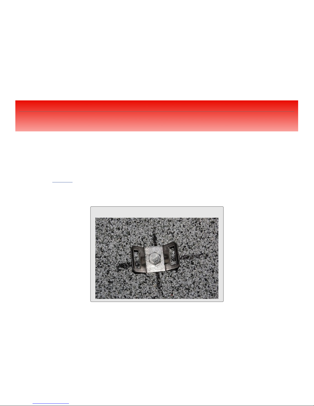
•Refer to Figure 2 throughout this section.
2

3
FIGURE 2Assembly on Roof Diagram
CHAPTER 1: MOUNTING THE SOLAR COLLECTORS
Figure 2: Assembly on Roof Diagram
3

CHAPTER 1: MOUNTING THE SOLAR COLLECTORS
Step One: Outlet Header Bracket Location
!Determine the position of the last Outlet Header Hold-Down Bracket for the row of collectors. Mark this point on
the roof. The Collector Outlet Headers will be located 1” (25mm) below this mark.
!Using this point, snap a chalk line to the opposite end of the row. Slope this line down the roof toward the
inlet a minimum of 1/8” per foot.
!Refer to Figure 3.
4
FIGURE 3Outlet Header Bracket Location

CHAPTER 1: MOUNTING THE SOLAR COLLECTORS
Step Two: Outlet Header Bracket Location
!Using a 1/8” (3mm) drill bit for 1/4” (6mm) diameter screws drill a hole for the first Outlet Header Bracket on the
first roof mark. Measure up 1” on center from the first pilot hole and drill pilot hole for second screw. Repeat this
process at 51” centers along the chalk line for the total number of collectors to be installed.
!Inject a generous amount of high quality sealant into each hole and onto the surrounding roof surface. Bolt all the
outlet header Hold-Down Brackets to the roof as shown in Figure 4.
5
FIGURE 4Outlet Header Bracket

CHAPTER 1: MOUNTING THE SOLAR COLLECTORS
Step Three: Hold-Down Strap Bracket Locations
!Locate the Hold-Down Strap Bracket holes using the information in Table 2A shown below.Measuring from the
top outlet header bracket chalk line, snap another chalk line parallel to this line using the “A” distance. The “B”
distance is the same for all collector sizes, which is 16” (40cm) up from the outside of the bottom header
and can be measured after the collectors are installed. Wait to install the Hold-Down Strap Brackets until after the
collectors are installed so as not to damage the collectors when you are bringing them to the roof for installation.
6
TABLE 2ADistance Between Panel Headers and Straps
COLLECTOR PANEL SIZE, FEET (M)
COLLECTOR (A) DISTANCE, INCHES (CM)
COLLECTOR (B) DISTANCE, INCHES (CM)
12 (3.6)
10 (3.0)
8 (2.4)
6 (1.8)
4 (1.2)
60 (152)
48 (122)
36 (91)
24 (60)
---
16 (40)
16 (40)
16 (40)
16 (40)
16 (40)

CHAPTER 1: MOUNTING THE SOLAR COLLECTORS
Step Four: Install Hose
!Bring the first collector to the roof and slip the proper hoses over both ends of the inlet and outlet headers on the
last return collector. Make sure that the header with the serial number label is used for the outlet or
top header with the serial number label facing downwards towards the mounting surface. The
System Connector Hoses (Part #60691-1 for 1 1/2”; # 60691-2 for 2”), go on the outlet of the last collector and the
inlet of the first collector. Place a Hose Clamp between the two indicator ridges on the hose, in order to center it
over the sealing groove in the header. This clamp must face up so as to be accessible for tightening and not rub
against the mounting surface.
!Make sure you securely tighten each clamp with a nutdriver. If a nutdriver is not available, a ‘hex’ wrench or
screwdriver will suffice. THE HOSE CLAMPS MUST BE LOCATED BETWEEN THE TWO INDICATOR
RIDGES ON THE HOSE. DO NOT OVER TIGHTEN!
!Refer also to Figure 2 on Page 3.
7

CHAPTER 1: MOUNTING THE SOLAR COLLECTORS
Step Five: Install Outlet Header Bracket with Hose
!Position the collector on the roof so that the center of the outlet connection hoses are directly beneath the secured
outlet header brackets. Open the clamp that is part of the outlet header bracket, insert connection hose and
LIGHTLY TIGHTEN the clamp around the hose. Loosely place another clamp over the open end of the hose
before installing the next collector in the array. Refer to Figure 5. Continue to install all the collectors in the array,
coupling them side to side.
!**If the Aluminum Header Clamp Assembly, Part #10117-1 for 1 1/2”; #10117-2 for 2”, or Outlet Header Clamp
Assembly, Part #10121 is to be used for supplemental mounting hardware, install them over the outlet header at
this time.
8
FIGURE 5Installed Outlet Header Bracket with Hose

CHAPTER 1: MOUNTING THE SOLAR COLLECTORS
Step Six: Install Hold-Down Strap Bracket
!Proceed to the lower chalk line previously snapped on the roof for the Hold-Down Strap Brackets. Mark a hole
2” (5cm) to the side of the first collector and continue marking holes on the chalk line centered exactly between the
absorber surfaces until you reach the last collector. Mark the last hole the same 2” (5cm) to the side of the last
collector. Drill a pilot hole and apply sealant at each of these locations. Bolt the Hold-Down Strap Brackets on the
roof. Refer to Figure 6. Mark the holes for the bottom Hold-Down Strap by measuring up 16” (40cm)
from the outside of the bottom header and again centering them between the absorbers and 2” (5cm) away
from the first and last collector. It is OK to step on the collectors as long as you stay one foot away from the top and
bottom headers.
9
FIGURE 6Strap Bracket

CHAPTER 1: MOUNTING THE SOLAR COLLECTORS
Step Seven: Install Strap
!Slip a Strap Hold-Down Clamp over one end of the strap prior to sliding the strap between both slots of the Hold-
Down Strap Bracket. Bend over approximately 3” of the strap (refer to Figure 7) and slide it through the one exposed
slot of the Hold-Down Strap Bracket and then back through the Hold-Down Strap Clamp. Slide the Hold-Down
Strap Clamp towards the Hold-Down Strap Bracket. Clamp screw should be tightened securely, but not over-
tightened to the point where the clamp is distorted. (refer to Figure 8)Bring the remaining strap end across the
collector face, passing through both slots in the bracket located on the other side of the collectors. Repeat strap
termination at opposite end. *Pull the straps taut against the face of the collectors. Repeat this procedure for the
remaining Hold-Down Strap. (refer to Figure 9)*
10
FIGURE 9Strap Bracket with Strap
FIGURE 7Termination Strap Bracket Assembly FIGURE 8Termination Strap Bracket Assembly

CHAPTER 1: MOUNTING THE SOLAR COLLECTORS
Step Eight: Install Vacuum Relief Valve
!Install the Vacuum Relief Valve (Part #10003-1 for 1 1/2”; #10003-2 for 2”) in the outlet header of each row. This
will be located at the opposite end of the header that is connected to the collector return line. Refer to Figure 10.
!DO NOT OVER TIGHTEN THE CLAMP!
!Also refer to Figure 2 on Page 3.
11
FIGURE 10 Installed Vacuum Relief Valve

CHAPTER 1: MOUNTING THE SOLAR COLLECTORS
Step Nine: Install End Cap
!Install an End Cap, (Part # 30061-1 for 1 1/2”; #30061-2 for 2”) in the inlet header of each row, opposite the end
that is connected to the collector inlet pipe. Refer to Figure 11.
!DO NOT OVER TIGHTEN THE CLAMP!
!Also refer to Figure 2 on Page 3.
12
FIGURE 11 Installed End Cap

CHAPTER 1: MOUNTING THE SOLAR COLLECTORS
Installation in High Wind Areas
!When Installing in High Wind Areas it is recommended to use the Optional Supplemental High Wind Area
Collector Hold-Down Kit, Part #12035-1 for 1 1/2”; #12035-2 for 2”.
!Install an Inlet Header Hold-Down Assembly to each of the panel’s inlet header connection hoses. Stretch the
spring 3/4” to locate the first hole. Using a 1/8” (3mm) drill bit for 1/4” (6mm) diameter screws drill a hole for the
first outlet header bracket on the first roof mark. Measure down 1” on center from the first pilot hole and drill pilot
hole for second screw. Insert a generous amount of high quality sealant into each hole and onto the surrounding
roof surface. Tension the bracket’s spring and bolt the bracket securely to the mounting surface. Repeat this step
for the other inlet connection hoses.
!NOTE: DO NOT STRETCH THE SPRING MORE THEN 3/4”. OVER TENSIONING THE SPRING
WHEN THE PANEL IS EXPANDED ON A HOT DAY CAN LEAD TO PANEL DAMAGE WHEN IT
CONTRACTS ON A COOL DAY/NIGHT.
!See Table 2B below for additional strap bracket locations.
13
TABLE 2B
COLLECTOR PANEL SIZE, FEET (M)
DIMENSION OF (A), INCHES (CM)
12 (3.6)
10 (3.0)
8 (2.4)
32 (81)
28 (71)
20 (51)

CHAPTER 2: SYSTEM PIPING
System Piping
• The most common piping configurations use a pressure filter. The pump draws the water from the skimmer and/
or a main drain, forcing it through the filter and sending it back to the pool through the return lines. (For other
types please contact factory)
If a fuel-fired heater or heat pump is installed, it is located between the collector return line and the return line to
the pool. The pipes to and from the solar collectors are connected to the return line to the pool before the water
enters the fuel-fired heater.
•Whenever there is more than 50 gpm (189L) required flow rate to the collectors or more than 100’ (30m) of
piping used in a system, install 2” (63mm) piping to and from the collectors. (See Table 3A for Pipe Size based on
Flow Rate.) Piping to and from the collectors should be the same type of plastic piping and fittings approved for
use with swimming pool filters and pumps. It is recommended to always use Schedule 40 PVC pipe and fittings.
•Although PVC pipe is generally white, black is also available but may be difficult to find locally. If for aesthetics
black pipe is desired it can always be painted black. Before painting, the PVC pipe must be wiped with cleaner to
remove the glossy surface coating. This will ensure that the paint will not flake off prematurely.
•Use a PVC cutter or a PVC wide-blade saw (not a hacksaw) for cutting pipe. It is important to use both a quality
cleaner/primer and solvent in gluing a PVC joint. Finally, use a cloth while either gluing or painting to keep the
job a clean one.
•Piping should also be supported at intervals based on pipe size. (See Table 3B) Aquatherm Industries Pipe
Brackets made from high-strength glass-reinforced polypropylene are available in 1 1/2” (Part #30272-1 black;
#30284-1 white) and 2” (Part #30272-2 black; #30284-2 white).
14

15
TABLE 3B Support Centers for Horizontal PVC Pipe
NOMINAL PIPE SIZE, INCHES
MAXIMUM DISTANCE BETWEEN CENTERS(FEET)
NOMINAL PIPE SIZE, INCHES
SDR & SCH. 40
SCH. 80
1-1/4; 1-1/2; 2
4-1/2
5
3
5-1/2
6
4
6-1/4
7-1/2
6
6-3/4
8-1/2
8
7-1/2
9
10
7-3/4
9-1/2
12
8
10
Note: Where Pipe sizes are not available or total pipe run exceeds 100ft, use the next larger size pipe.
TABLE 3A Minimum Pipe Sizes and Slope
FLOW RATE, GPM
(LESS THAN)
PIPE SIZE, INCHES
MINIMUM PIPE SLOPE,
INCH/FT
50
1 1/2
1/4
80
2
1/4
120
2 1/2
1/4
180
3
1/8
300
4
1/8
600
6
1/8
1000
8
1/16

CHAPTER 2: SYSTEM PIPING
Flow Rate
•In order to receive optimum performance from Aquatherm Industries collectors, the following recommended
flow rates and number of collectors per row should be followed. When the system is running, all the collectors
should feel uniformly cool to the touch, and there should be no residual air left in the pool return lines. If either
of these two conditions persist, chances are that the flow rates thru the collectors are inadequate or the system is
not properly balanced. A flow meter can be installed in the collector feed line to check on the flow rate. If the flow
rates are within the limits as shown below in Table 3C, then the system may not be properly balanced, especially
with systems requiring multiple banks of collectors.
•If the flow rate is below the minimum as shown in the table above, then the pool pump size or pipe size should be
increased, or a booster pump installed in some cases. If the flow rate is excessive (more than 10 GPM/(37.9l )
collector), or if the system pressure is greater than 30 psi, a by-pass Check Valve should be installed between the
collector feed and return lines above the 3-way valve to prevent problems with the collectors and connection
hoses.
•If there is residual air in the pool return lines and the collectors do feel cool to the touch, refer to the section
concerning the Vacuum Relief Valve Test on Page 23.
16
TABLE 3C
COLLECTOR SIZE, FEET:
4 X 12
4 X 10
4 X 8
STANDARD FLOW RATE PER COLLECTOR, GPM (LTR/MIN)
MINIMUM FLOW RATE PER COLLECTOR, GPM (LTR/MIN)
MAXIMUM # COLLECTORS PER ROW, 1 1/2”; 2”
MAXIMUM SQUARE FOOTAGE PER ARRAY, 1 1/2”; 2”
PRESSURE DROP, PSI@GPM: 1 1/2”;
2”
5.0 (18.9)
4.0 (15.1)
3.25 (12.5)
3.0 (11.4)
2.5 (9.5)
2.5 (9.5)
10; 12
12; 12
12; 14
480; 576
480; 576
480; 576
0.05 @2.5

CHAPTER 2: SYSTEM PIPING
Reverse Return
!Refer to Figure 12.
17
FIGURE 12 Reverse Return

CHAPTER 2: SYSTEM PIPING
Direct Return
!Refer to Figure 13.
18
TABLE 3D Number of Recommended Collectors to Use in a Direct Return System
COLLECTOR SIZE:
COLLECTOR SIZE:
8’
8’
10’
10’
12’
12’
1 1/2”
2”
1 1/2”
2”
1 1/2”
2”
MINIMUM FLOW RATE (0.06 GPM/FT²)
STANDARD FLOW RATE, (0.10 GPM/FT²)
RECOMMENDED FLOW RATE, (0.15 GPM/FT²)
MAXIMUM FLOW RATE, (10 GPM PER COLLECTOR)
-
-
-
-
-
-
6
6
6
6
6
6
7
8
7
8
7
7
8
12
8
10
8
8
FIGURE 13 Direct Return

CHAPTER 2: SYSTEM PIPING
Optional Isolation Valves
• Isolation valves may be installed in the collector piping so that the pool may be operated while the collectors are
being serviced or during freezing weather. Install a manually operated ball valve in the collector inlet line and a
check valve on the collector return line. Both valves, available in the Optional Supplemental System Isolation Kit
(Part #12033-5) are made to accept either 1 1/2” or 2” PVC pipe. Make sure that the arrow on the check valve is
pointing away from the collectors, and that the ball valve and check valve are located close to the control valve
and outlet ‘T’, respectively.
• For further precautions in warm climates where pools are operated year round and periodic freezes can occur, a
bypass line (small diameter tubing, See Page 21) can be located above the ball and check valve so as to prevent
any accidental trapping of water in the collectors by the pool owner. To make sure no water is left in the collectors
for servicing or during freezing conditions, remember that the pool pump should be shut off, allowing the
collectors to drain naturally, before the optional isolation valves are used.
• If the system is installed on a commercial or public pool, local codes may require positive isolation valves in the
collector feed and return lines.
19
Table of contents
Popular Swimming Pool Heater manuals by other brands

Tuuci
Tuuci OCEAN MASTER MAX operating instructions

Zodiac
Zodiac Jandy Legacy LRZ Millivolt Installation and operation manual

SUNHEATER
SUNHEATER S2220AG Installation & operation manual

Amerec
Amerec Pro 12.0 user manual

Jandy
Jandy LJ Installation and operation manual

Raypak
Raypak 180A Illustrate parts list

Certikin
Certikin MB055 Operating & installation guide

Sungrabber
Sungrabber Solar Pool Heater Installation & owner's manual

FAFCO
FAFCO Solar Bear Installation & owner's manual

Raypak
Raypak 153A GEMINI Illustrate parts list

Prem-I-Air
Prem-I-Air EH1372 owner's manual

STA-RITE
STA-RITE Max-E-Therm SR200NA owner's manual