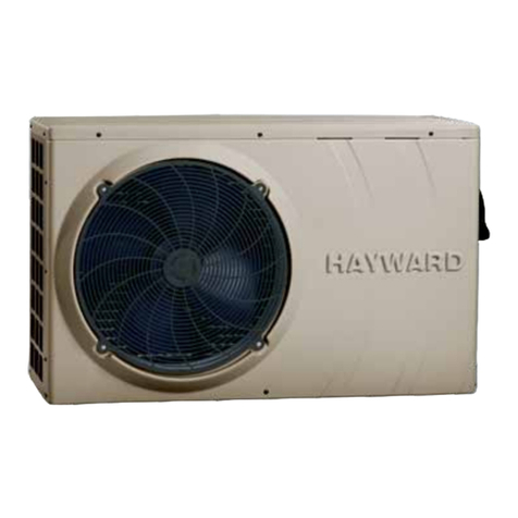
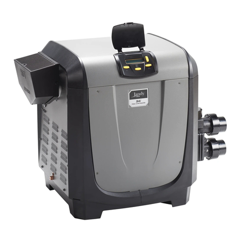
PoolRite PoolTherm PASRW020 Service manual

INSTALLATION & INSTRUCTION MANUAL
www.poolrite.com.au
P-Series
Heat Pump Swimming Pool Heater

CONTeNTS
1. Preface 1
2. Specifications 2
2.1 Performance Data of Swimming Pool Heat Pump Unit 2
2.2 Dimensions for Swimming Pool Heat Pump Unit 3
3. Installation and Connection 4
3.1 Typical Installation 4
3.2 Swimming Pool Heat Pumps Location 5
3.3 How Close to Your Pool? 5
3.4 Swimming Pool Heat Pumps Plumbing 6
3.5 Swimming Pool Heat Pumps Electrical Wiring 7
3.6 Initial Start-up of the Unit 7
3.7 Wiring Diagrams 8
3.7 Wiring Diagrams (Continued) 9
4. Usage and Operation 10
4.1 Quick Start Guide 10
4.2 The Functions of the LCD Controller 11
4.3 How to Set Operation Parameter 11
4.4 To Choose Mode 12
4.5 How to know the Current Status 12
4.6 Operation Data Setting 13
5. Maintenance and Inspection 14
5.1 Maintenance and Inspection 14
5.2 Malfunction Guide 14
5.3 Guide for Poor Heat Gain 15
5.4 Customer Responsibilities 15
6. Appendix 16
6.1 Connection of PCB Illustration 16
6.2 Connections Explanation 16
6.3 Connection of protection PCB Illustration 17
6.4 Connections Explanation 17
6.5 Fault Explanation 18
7. Warranty Conditions 19

1
1. PRefACe
In order to provide our customers with quality and reliability, this product has been made to strict production standards.
This manual includes all the necessary information about installation, debugging, discharging and maintenance. Please
read this manual carefully before you open or maintain the unit.
Poolrite Equipment Pty Ltd will not be held responsible if someone is injured or the unit is damaged, as a result of
improper installation, debugging or unnecessary maintenance. It is vital that the instructions within this manual are
adhered to at all times.
NOTE: The unit must be installed by qualified personnel. Before obtaining access to electrical connections, all supply
circuits must be isolated or disconnected.
THE HEAT PUMP IS NOT INTENDED FOR USE BY YOUNG CHILDREN OR INFIRM PERSONS WITHOUT SUPERVISION.
YOUNG CHILDREN SHOULD BE SUPERVISED TO ENSURE THEY DO NOT PLAY WITH THE HEAT PUMP
WARRANTY CONDITIONS
The warranty must comply with the following terms:
The unit can only be repaired by Poolrite personnel or an authorized dealer
Maintenance must be carried out periodically, or as required
Only genuine Poolrite spare parts should be used
NOTE: Failure to comply with these recommendations will void warranty
HEAT PUMP FEATURES
This type of heat pump has the following features:
1. Durable
The heat exchanger is made of PVC and TITANIUM TUBE which can withstand prolonged exposure to corrosives such as
chlorine.
2. Installation flexibility
The unit can be installed outdoors or indoors.*
(*) Must comply with Australian standards of installation. Indoor installations should not recirculate expelled air.
3. Quiet operation
The unit comprises an efficient rotary/scroll compressor and a low noise fan motor, which guarantees its quiet operation.
4. Advanced controlling
The unit includes a digital programmable controller which allows all operating parameters to be set.

2
2. SPeCIfICATION
2.1 Performance data of Swimming Pool Heat Pump Unit
UNIT (SINGLE PHASE POWER) Model PASRW020 PASRW030 PASRW050
Heating Capacity kW 12 16 26
BTU/h 41,000 54,600 88,700
Heating Power Input kW 1.7 2.6 5.1
Running Current amp 7.8 11.8 21.8
Running Current with Slave Pump amp 17.8 21.8 31.8
Power Supply V/Ph/Hz 220-240/1/50 220-240/1/50 220-240/1/50
Compressor Quantity 1 1 2
Compressor rotary rotary scroll
Fan Quantity 1 1 1
Fan Power Input watts 120 120 200
Fan Rotate Speed RPM 870 850 850
Fan Direction horizontal horizontal upwards
Noise dB(A) 52 54 54
Water Connection mm 40 40 40
Minimum Water Flow Requirements L/min 100 100 150
Water Pressure Drop(max) kPa 10 12 8
Unit Net Dimensions (L/W/H) mm
905/420/650 905/420/650 660/660/880
Unit Shipping Dimensions (L/W/H) mm
990/480/700 990/480/700 900/700/900
Net Weight/Shipping Weight kg 65/70 75/80 130/138
UNIT (3 PHASE POWER) Model PASRW050S-U PASRW060S-U PASRW100S PASRW130S
Heating Capacity kW 26 32 55 62
BTU/h 88,700 109,200 187,700 211,500
Heating Power Input kW 4.6 5.2 9.2 10.4
Running Current amp 8.1 8.8 16.6 17.6
Running Current with Slave Pump amp 18.1 18.8 26.6 27.6
Power Supply V/Ph/Hz 380-415/3/50 380-415/3/50 380-415/3/50 380-415/3/50
Compressor Quantity 1 1 2 2
Compressor scroll scroll scroll scroll
Fan Quantity 2 1 2 2
Fan Power Input watts 200 200 400 400
Fan Rotate Speed RPM 850 850 850 850
Fan Direction upwards upwards upwards upwards
Noise dB(A) 59 59 61 61
Water Connection
mm
40 40 50 50
Minimum Water Flow Requirements L/min 150 160 300 360
Water Pressure Drop (max) kPa 8 10 12 12
Unit Net Dimensions (L/W/H) mm
660/660/880 650/650/880 1450/730/1060 1450/730/1300
Unit Shipping Dimensions (L/W/H) mm
760/700/930 760/700/930 1510/790/1155 1510/790/1450
Net Weight/Shipping Weight kg 125/135 135/145 250/270 265/285

3
2. SPeCIfICATION
2.2 Dimensions for Swimming Pool Heat Pump Unit
Unit Model
PASRW020/030
PASRW050S-U/060S-U
PASRW050-U/060-U
PASRW100S-U/130S-U

4
3. INSTALLATION ANd CONNeCTION
3.1 Typical Installation
Water inlet
Valve
Water supply
Chlorinator cell Water Outlet
Pool
Sand filter
(or other type filter)
3 Way Valve3 Way Valve
In Out
Heat Pump
Water pump
Note: Install on a clean concrete base
Bypass

5
3. INSTALLATION ANd CONNeCTION
3.2 Swimming Pool Heat Pumps Location
The unit will perform well in any outdoor location provided that the following three factors are present -
1. Fresh Air — 2. Electricity — 3. Pool filter piping
The unit may be installed virtually anywhere outdoors. For indoor pools consult the supplier. Unlike a gas heater, it has no
draft or pilot light problem in a windy area.
DO NOT place the unit in an enclosed area with a limited air volume, where the units
discharge air will be re-circulated. DO NOT place the unit close to shrubs which can block the air inlet. These locations
deny the unit of a continuous source of fresh air which reduces its efficiency and may prevent adequate heat delivery.
3.3 How Close To Your Pool?
Normally, the heat pump is installed within 7.5 metres of the pool. The longer the distance from the pool, the greater the
heat loss is from the piping. For the most part, the piping is buried. Therefore, the heat loss is minimal for runs of up to
15 metres (15 metres to and from the pump = 30 metres total), unless the ground is wet or the water table is high. A very
rough estimate of heat loss per 30 metres is 0.6 Kw-hour, (2000 BTU) for every 5˚C difference in temperature between
the pool water and the ground surrounding the pipe, which translates to about a 3% to 5% increase in run time.
A. Side Discharge
B. Top Discharge
(Air Outlet Side > 1500mm)
600mm
600mm
600mm
ROOF

6
3. INSTALLATION ANd CONNeCTION
3.4 Swimming Pool Heat Pumps Plumbing
Poolrite advises that a bypass valve setup, including 2 x 3 way valves be incorporated into the plumbing between the
inlet and outlet pipe work of the heat pump, for servicing requirement’s and winterizing of the heat pump.
PVC connections to the heat pump can either be 40mm or 50mm (class 9 or greater) depending on the requirement’s of
the plumbing provided.
Condensation:
Since the heat pump cools down the air by approximately 4 to 5°C the condenser will gather condensation. If the relative
humidity is very high this could be as much as several litres per hour. The water will run off the condenser into the base
pan and drain out through the drain hole fitting.
NOTE: Condensation can be mistaken for a water leak inside the unit.
A quick way to verify that the water is condensation, is to turn the heat pump off and keep the pump running. If the water
stops running out of the base pan then it is condensation. You could even check the drain water for chlorine. If there is no
chlorine present, then it is condensation.
From Pump
To Pool
PVC COUPLER
RECOMMENDED (Provided)
CONDENSATION DRAIN
BARB FTG PROVIDED

7
3. INSTALLATION ANd CONNeCTION
3.5 Swimming Pool Heat Pump Electrical Wiring
NOTE: Electrical wiring and earthing should comply with local wiring rules, including a means of
isolating all active conductors with air gap contact separation.
3.6 Initial start up of the unit
NOTE: In order for the heat pump to operate, the water pump must be operating to circulate water
through the heat exchanger
Start up procedure – After installation is completed, you should follow these steps:
Caution: Ensure glued pipework is fully cured before running/starting the recirculation water pump.
1. Fully open the bypass valves ensuring that the bypass pipe is closed off
2. Prime the pump
3. Purge air from the heat exchanger by running the pump
4. Start the heat pump. For 3 phase units, the direction of rotation can be checked with a pressure switch error message
EE04 or the phase monitor will indicate “incorrect phase”
5. Adjust bypass flow so that the temperature out is 2 degrees Celsius more than the temperature in
6. After the heat pump has been running a few minutes check that the air leaving the heat pump is cooler than the
ambient temperature.
7. With the heat pump running, turn the water pump off. The heat pump will then go into standby mode after a few
seconds.
8. We recommend that the heat pump runs continually to achieve desired water temp (NOTE:THIS MAY TAKE SEVERAL
DAYS DEPENDING ON CLIMACTIC CONDITIONS AND EXPOSURE TO WEATHER) When the desired temperature is
reached the heat pump will go into standby mode until the temperature drops to 2 degrees below the set temperature
Water Flow Switch –Each heat pump is equipped with a flow switch that turns the unit on when the water pump is
running. The unit turns off automatically when the water pump is stopped
Time Delay – The heat pump software is programmed with a time delay to ensure that the heat exchanger is flooded
before the compressor starts

8
3. INSTALLATION ANd CONNeCTION
3.7 Wiring Diagrams

9
3. INSTALLATION ANd CONNeCTION
3.7 Wiring Diagrams
RK1: Contactor coil of compressor 1
RK2: Contactor coil of compressor 2
RKB: Relay coil of water pump
Temp.
Sensor
Temp.
Sensor Temp.
Sensor
Temp.
Sensor
Temp.
Sensor
RK1: Contactor coil of compressor 1
RK1: Contactor coil of compressor 2
RKB: Relay coil of water pump
RKF: Relay coil of fan motor
To water pump
380VAC/3PH/50H Hz
To power supply
380VAC/3PH/50H Hz

10
4. USAge ANd OPeRATION
4.1 Quick Start Guide
Overview of LCD Remote Panel:
Unit Status – LCD Display Shows:
To Change Desired Temp:
Ensure the unit is in “OFF” Status (above) by pressing Power Button O on far left of LCD remote. Keep pressing “SET”
button until “SET 01” is seen (diagram below). Then change temp settings by using up/down arrows. Press power button
again to turn unit back “ON”.
Press to turn on and
turn off the unit
Press M button to change modes Press SET to set operation parameter
under standby status or check the operation
parameter under running or standby status.
Initialisation
Heating mode.
Standby status. The LCD
displays ambient temp. and
current mode
Off: On:
Parameter 01
To set the entering water temp. Under
heating mode (15-40°C).
Default setting: 40°C

11
Parameter 00
Cooling Set Point Parameter 01
Heating Set Point
Parameter 02
Defrost Function
Start Delay
Parameter 03
Defrost Start
Set Point
Parameter 04
Defrost Stop
Set Point
Parameter 05
Defrost Function
Time Limit
Cooling mode
(‘SNOW’ symbol)
LCD Screen
Heating mode
(‘SUN’ symbol)
water outlet temp.
Parameter valve
Press to start auxiliary
electrical heating only
Press to set and check the
operatation data.
Press button to choose cooling
and heating mode
Press to turn on and
turn off the units
Standby status
The LCD display ambient temp.
and current mode.
4. USAge ANd OPeRATION
4.2 The Functions of the LCD Controller
4.3 To adjust the heat pump operation parameters, the unit must be in “Standby”
The unit is in “Standby” when the LCD displays only the “Room temp”
• When in Standby, use the “SET” button to make adjustments to the parameters
• Keep pressing “SET” to scroll through & make adjustments to the parameters (00–09)
• Note: Parameters 02–09 must be unlocked to make changes. Press & hold both arrow buttons for 3 seconds
to lock & unlock
• Use the arrows “ “ “ “ to change the settings of each parameter
• Check all Parameters re set to correct values (as per table below)
• Press to turn unit on

12
Water temp.
of inlet / outlet Condenser 1 temp. Ambient temp.
Condenser 2 temp.
4.5 How to know the Current Status?
4.4 How To Choose Mode
4. USAge ANd OPeRATION
• Press “M” to choose mode (mode can be changed under running)
• Press “ “ to power on unit. Under running, the LCD displays the water-in temp., water-out temp. and current mode.
• Aux. Elec. Heating – NOT APPLICABLE FOR THESE MODELS.
• Under running, press “ “ “ “ to check the current status of the unit. You
can check water-in / water-out temp, condenser temp. and ambient temp.
If no buttons are depressed within 5 seconds, the LCD will display
water-in/water-out temp. When the unit is switched off, current ambient
temperature is displayed.
Parameter 09
Heat on demand mode
1 (Yes) 0 (No).
Cooling mode Heating mode
Parameter 06
Compressor Number
Parameter 07
Can save setting after power off
or not. 1 (Yes) 0 (No).
Parameter 08
Mode: 0. (Cooling only)
1. (Cooling & heating)
2. (Auxiliary elec. heating)
3. (Heating only)
4.3 (Continued)

13
4. USAge ANd OPeRATION
The unit’s operation data can be set on the wire controllers. Please set according to the table:
Data Description Range Default Adjustable
00 Temperature Setting (cooling mode) 8-28°C 30°C YES
01 Temperature Setting (heating mode) 15-40°C 27°C YES
IMPORTANT: Consult your authorised dealer before making any changes to the following settings.
02 Defrost function start delay 30–90min 45min YES
*03 Defrost start set point -30–0°C -6°C YES
04 Defrost stop set point 0–30°C 13°C YES
05 Defrost Function time limit 0–15min 8min YES
06 Compressor number 1–2 2 YES
07 Status memory 0–1
0 (OFF) - 1 (ON) 1 YES
08
Operating Mode (cooling only/cooling
& heating/auxiliary electrical heating/hot
water/heating only
0 - Cooling
1 - Cool & Heat
2 - Aux Heat
3 - Heating
3 YES
09 Heat On Demand mode 0 (OFF) - 1 (ON) 0 YES
IMPORTANT – Installer please note:
HEAT ON DEMAND WIRING CHANGES
For the 55kw & 62kw unit:
The flow switch from terminals 18 and 20 need’s to be placed into terminal’s
16 and 17. And the jumper wire from terminal’s 16 and 17 need’s to be placed into terminal’s 18 and 20.
NOTE: THIS SHOULD BE DONE ON THE TERMINAL STRIP: LOCATED ON THE RIGHT HAND SIDE
OF THE ELECTRICAL CONNECTION BOX
For all other unit’s: The flow switch from terminals 18 and 20 need’s to be placed into terminals 21
and 22. And the jumper wire from terminals 21 and 22 need’s to be placed into terminal’s 18 and 20
NOTE: THIS CHANGE IS MADE ON THE CHILLER 300 INPUT TERMINALS
NOTE
• Parameter 03:
0–30˚C means from (-30˚C) to (0˚C).
6˚C means (-6˚C)
• To enter parameters 02–09 both “ “ and “ “ must be pushed together for three seconds.
The controller will now unlock these parameters and will except required inputs.
Parameters 02–09 will auto–lock after ten seconds, provided no other buttons are pressed.
• When heat on demand is selected, the unit will operate the pump 10 minutes after the inlet
temperature falls below the set point. The compressor will not start unless the water sample
indicates that the pool water requires heating (or cooling). If heating or cooling is not
required, then the pump will stop after 1 minute.

14
5. MAINTeNANCe ANd INSPeCTION
5.1 Maintenance and Inspection
You should eliminate causes of prime loss and ensure unrestricted water flow. Clear debris from the pool/spa and pump
baskets regularly to avoid damage to the heat pump. Ensure the area around the heat pump is well ventilated and free
from debris and flooding. The evaporator/condenser should be well maintained at all times with no obstructions that will
affect the heat pumps performance.
WARNING: If debris such as leaves accumulate inside the unit, they could block the drain hole and cause corrosion to the
heat pump.
A refrigeration mechanic should be employed to do periodic maintenance to the heat pump, including cleaning the
condenser, checking gas levels and removing debris from inside the unit.
NOTE: Should the heat pump start working abnormally, switch it off and contact your authorized Poolrite technician.
If the heat pump is not to be used for an extended period of time then isolate power to the unit, and empty the heat
exchanger of water. This will avoid internal damage to the heat exchanger. It is advised to flush the heat exchanger with
non chlorinated fresh water or town water.
NOTE: The heat pump must be fully charged with water before power is restored, to avoid any damage to the unit.
5.2 Malfunction Guide
LCD CONTROLLER MALFUNCTION RESOLUTION
PP01 Water inlet temperature sensor failure Check for water contamination or damaged wiring.
Repair or change as necessary
PP02 Water outlet temperature sensor failure Check for water contamination or damaged wiring.
Repair or change as necessary
PP03 Coil 1 sensor 1 failure Check for water contamination or damaged wiring.
Repair or change as necessary
PP04 Coil 2 sensor 2 failure Check for water contamination or damaged wiring.
Repair or change as necessary
PP05 Ambient temp.Sensor failure Check for water contamination or damaged wiring.
Repair or change as necessary
PP06 Temp. Difference between in and out is too great Check water flow rate, eliminate obstructions,clean filters etc.
Adjust bypass flow as necessary
PP07 Anti freezing of heat exchanger Check water flow volume
PP08 Ambient freezing protection Ambient temp. Too low
PP09 Ambient freezing protection Ambient temp. Too low
EE01 Malfunction of system 1 Check protection point of system 1.
Check temperature and gas pressures
EE02 Malfunction of system 2 Check protection point of system 2.
Check temperature and gas pressures
EE03 Flow switch failure or not enough flow Check flow or replace flow switch
EE04 (55 + 62KW) Incorrect phase configuration Reconfigure phase connection
EE04 (12/16/26/32 KW) Gas charge too low or high or system blocked Check pressure switches or gas levels
EE05 Difference between water in and out temp too high Eliminate obstructions. Clean filter etc.
Adjust bypass flow as necessary
EE08 Communication failure Check lcd controller and pcb connection
No Display(26/32 KW) Incorrect phase configuration Reconfigure phase connection

15
5. MAINTeNANCe ANd INSPeCTION
5.3 Guide for Poor Heat Gain
POOL WATER IS NOT HEATING UP:
•Is the heat pump turned on ?
•What is the temperature set too ?
•Is there sufficient water flow ?
•How long is the heat pump set to run for ?
•Are there any water features ?
•Does the pool have a blanket ?
•What is the ambient temperature ?
•Is the condenser covered in ice ?
•Are bypass valves closed off ?
NOTE: IF THE CONDENSER IS COVERED IN ICE
Set the parameter 02 to 30 minutes
Set parameter 03 to 0
Set parameter 05 to 15 minutes
5.4 Customer Responsibilities
BEFORE YOU CALL FOR SERVICE read the following points carefully which are your responsibility.
•A service charge will be made for service as a result of:
•Power not turned on or disrupted
•Heat pump not set to run for a long enough period
•Heat pump installed incorrectly
•Recirculation pump not operating correctly
•Controls incorrectly set
•Poor water chemistry (Salt Level, pH, etc)
•Poor water flow (Check filter is clean/Pump operation/Skimmer free of obstructions and bypass flow is not excessive)
•Heat pump being tampered with by unauthorized persons
• Excessive ambient conditions

16
6. APPeNdIX
6.1 Connection of PCB illustration
6.2 Connections explanation
CHILLER 300
240 VAC 50Hz.12 VDC
Wire No. Port No. Symbol Meaning
11 HEAT Auxillary heater output (220VAC)
10 PUMP Demand pump ouput (220VAC)
9 FAN Fan motor output (220VAC)
8 VAL2 4way valve of system2 (220VAC)
7 VAL1 4way valve of system1 (220VAC)
6 COMP2 Compressor of system2 (220VAC)
5 COMP1 Compressor of system1 (220VAC)
4 AC-L Active power supply
1,2,3 AC-N Neutral wire
21 12 KYOUT GND On/Off switch (output) (not used)
22 13 MDOUT GND Mode output (not used)
26,27,28 14,15,16 NET GND 12V Wire controller
18 18 KYIN On/Off Switch (input)(not used)
19 19 MDIN Model (input) (not used)
16,17 21,22 WATER GND Flow switch (input)( normal close)
24,25 23,24 FROST GND Defrost signal (not used)
29,30,31 25,26,27 SYS GND 12V System protection (input)(normal close)
32 ROOMT Ambient temp. (input)
31 PIPE2 Temp. Of fan coil2 (input) (not used)
30 PIPE1 Temp. Of fan coil 1 (input) (not used for split type)
29 OUTWT Water out temp. (input)
28 INTWT Water in temp. (input)
1
2
3
4
5
6
7
8
9
10
11
12
13
14
15
16
17
18
19
20
21
22
23
24
25
26
27
28
29
30
31
32
WIRE NO.
WIRE COLOUR

17
6. APPeNdIX
6.3 Connection of protection PCB illustration
CT
Current
Transformer
CT
Current
Transformer
CT
Current
Transformer
CT
Current
Transformer
WIRE NO.
WIRE COLOUR
5
6
7
8
9
10
11
12
13
14
15
16
17
12
7
8
10
13
11
6.4 Connection explanation
Wire No. Port No. Symbol Meaning
12,13 5,6 HIGH H2 GND High pressure protection for system 2 (normal close)
14,15 7,8 LOW 2 GND Low pressure protection for system 2 (normal close)
7,8 9,10 HIGH H2 GND High pressure protection for system 1 (normal close)
10,11 11,12 LOW 1 GND Low pressure protection for system 1 (normal close)
29,30,31 13,14,15 SYS GND 12V Protection signal
SW Current setting (handset)
12 CMP2 Exhausting temp. Of compressor 2
7 OUTW2 Refrigerant temp. After tube (system2) NC
8 INW2 Refrigerant temp. Before tube (system2) NC
13 CMP1 Exhausting temp. Of compressor 1
10 OUTW1 Refrigerant temp. After tube (system 1 (NC)
11 INW1 Refrigerant temp. Before tube (system 1) NC

18
6. APPeNdIX
6.5 Fault explanation
Display Failure Cause Unit Action Solution
3Low pressure
protection
Low pressure
switch tripped Stop and alarm 1, Check if low pressure switch is ok/is refrigerant leaking 2, change low pressure
switch or recharge refrigerant and find leak
4
Extra high
exhaust temp.
Protection
Exhaust temp.
Of comp.
Is too high
Stop and alarm 1, Check if there is an obstruction in the gas system/check water flow is ok under
heating mode; 2,change blocked parts and make water flow smoothly
5Over current
protection
Compressor
current draw
too high
Stop and alarm 1, Check if there is loss of power phase/check if the loop of the compressor is short
circuited; 2,examine and repair power supply/change the compressor.
6High pressure
protection
High pressure
switch tripped Stop and alarm
1, Check if high pressure switch is ok/check if there is any obstructions in the gas
system.Check if the fan works well 2,change h-p switch/remove blocked parts
repair fan
9
Temp.Sensor
of compressor
failure
Problem with
the temp sensor Stop and alarm 1, Check if the exhaust temp.Sensor of the compressor is good;2,replace temp sensor
E
Power phase
sequence
protection
Wrong or
loss of power
supply
Stop and alarm 1, Check if there is something wrong with the power supply, 2,swap two of the three
phase of power supply/remove power supply failure
This manual suits for next models
7
Table of contents
Popular Swimming Pool Heater manuals by other brands

Pentair Pool Products
Pentair Pool Products MiniMax NT Series Operation & installation manual
Aqua Comfort
Aqua Comfort Heat pump pool heater owner's manual

Calorex
Calorex AW629AL installation manual

Space-Ray
Space-Ray PTS 40-N7/L7 Installation and operation instructions

Leisure Temp
Leisure Temp LT600 installation manual

Raypak
Raypak 180A Illustrate parts list

Hayward
Hayward H-Series Installation, operation & service procedures

Dimplex
Dimplex XLN operating instructions

Intex
Intex HT30221-1 owner's manual

Rheem
Rheem Raypak XTherm 1005A Installation & operating instructions

Water Furnace
Water Furnace Envision Installation information

Shenbao
Shenbao SBR-50.0H-A-S Installation instructions manual