2
www.HomewerksWW.com
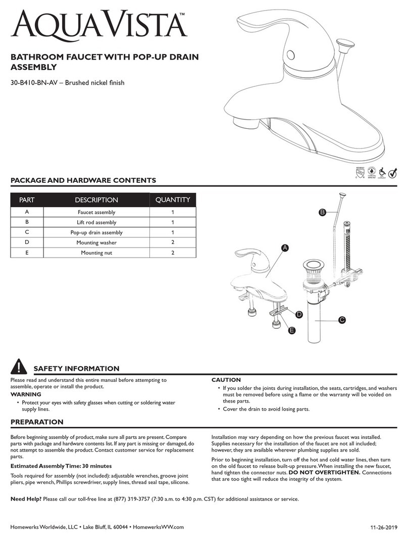
PRODUCT SPECIFICATIONS
Max. Flow Rate: 1.8 GPM (6,814 LPM) at 60 PSI Ceramic cartridge
ASME A112.18.1/CSA B125 Manufactured to include no more than 0.25% weighted average lead content
on wetted surfaces
NSF 61-9
Polished chrome or brushed nickel finish Total weight of item: 3.90 lbs.
ASSEMBLY INSTRUCTIONS
1.
Turn off water at the supply valve
under the sink or at the main water
supply. Disconnect the supply lines
to the faucet and remove the old
faucet.
Clean and dry the surface area
where new faucet will be mounted.
1
5.
From underneath the sink, install
the metal washer (C) onto the
threaded shank (5.
1
) on the
faucet body (A). Secure the lock
nut (B) onto the shank (5.
1
) until
firmly against the bottom of the
sink. Secure the lock nut (B) into
position by tightening the hex
bolts (D). Do not overtighten. 5.1
C
B
D
A
5
2. Before installation, remove the quick
connector (2.1) from the end of the
spray hose (2.2) by turning it in a
counterclockwise direction. Unscrew
the lock nut (B) and remove the
metal washer (C) from the bottom
of the faucet body (A).
2
6.
After inserting the tubes (6.
1
)
through the hole in the sink pull
the hose (6.2) back down through
the faucet body (A), and attach
the quick connetor by screwing it
into the end of the hose (6.2) in a
clockwise direction. Hand tighten
only.
6.2
6.1
6.
A
3
6
3. Pull the hose (3.3) up through the
faucet body (A) until the end of the
hose (3.3) is flush with the bottom
of the shank (3.4) on the faucet
body (A). Do not pull the end of the
hose (3.3) past the bottom of the
shank (3.4) on the faucet body (A).
Insert the faucet body (A) with the
attached flange (3.1) through the
mounting hole in the sink (3.2).
NOTE: Do not feed the hose (3.3)
back down through the faucet body
(A) unitl step 7.
3.4
3.2
3.1
3.3
A
3
7.
Push the quick connector (7.
1
)
firmly upward and attach it to the
receiving block (7.2). Pull down to
ensure the connection is secure. If
necessary to detach the quick
connector (7.
1
), squeeze the tabs
(7.3) and then pull down to
disconnect. After connecting the
hose, attach the weight (E) at the
position on the hose (7.5) marked
“weight here”. 7.2
7.3
7.1
G
Weight
here
7.5
G
7
4.
Optional deckplate installation:
Note: Optional deckplate (E) and
gasket (F) cannot be installed
with the flange (4.1).
Remove the flange (4.
1
) from the
faucet body (A). Apply a thin bead
of silicone sealant to the underside
of the optional gasket (F). Place
the optional gasket (F) and the
optional deckplate (E) over the
three mounting holes in the sink.
Insert the faucet body (A) through
the hole in the deckplate (E) and
the hole in the sink.
48.
To connect the water supply, use
1/2 in. IPS faucet supply lines (8.1)
or coupling nuts (8.2) with 3/8 in.
O.D. ball-nose risers (8.3).These
parts are not included.
To tighten each faucet connector
to the water supply line, place the
first wrench on the faucet
connector (8.4) shank to hold it in
place while tightening the supply
line (8.1) fitting with a second
wrench.This will prevent the
copper tube from twisting when
tightening the faucet connector.
Do not overtighten.
8.2
8.1
8.
8.4
3
8
NOTE: The hot side inlet tube is indicated by a label.When making water
line connections, DO NOT OVERTIGHTEN. Do not use PTFE pipe tape,
plumber's putty, pipe dope, or any other type of sealing compound on the
water inlets or threads.Additional compound is not necessary.A watertight
seal between the threaded inlet and supply line is achieved by compression.


