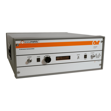
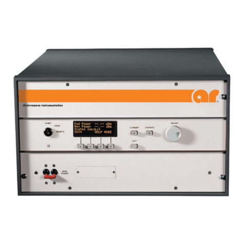
AR 681 Service manual

Operating and
Service Manual
681
Model
10029616
Part Number
Serial Number
EXPORT CONTROLLED DATA.
These commodities, technology or software are controlled for export in accordance with the U.S. Export
Administration Regulations. Diversion contrary to U.S. law is prohibited.
160 School House Road, Souderton, PA 18964 • 215-723-8181 • Fax 215-723-5688 • www.arworld.us

WARNING: EXPORT-CONTROLLED

Declaration of Conformity
Issue Date: July 28, 2009
Model #/s: 681
Type of Equipment: RF broadband amplifier
Function: Designed to be used in a RF immunity test system or for research. The unit is intended
to amplify an RF signal and inject it into a load.
The equipment described above is declared to be in conformity with the following applicable national and
international standards. The conformity is valid only when equipment is used in a manner consistent with the
manufacturer’s recommendations and the reference documents.
EMC Directive 2004/108/EC
Reference standards:
EN 61326:2006 Electrical equipment for measurement, control and laboratory use–EMC requirements
CISPR 11 Edition 4:2003 Conducted Emissions, Group 1, Class B
CISPR 11 Edition 4:2003 Radiated Emissions, Group 1, Class B
IEC 61000-3-2:2000 Harmonics
IEC 61000-3-3:2002 Flicker
EN 61326:2006 Electrical equipment for measurement, control and laboratory use–Immunity
requirements
IEC 61000-4-2:2001 Electrostatic Discharge
IEC 61000-4-3:2002 Radiated Immunity
IEC 61000-4-4:2004 EFT/Burst, Power Leads
IEC 61000-4-5:2001 Surge Immunity
IEC 61000-4-6:2003 Conducted Immunity, Power Leads
IEC 61000-4-11:2004 Voltage Dips and Interrupts
LVD Directive 2006/96/EC
Reference standards:
EN 61010-1:2010 Safety requirements for electrical equipment for measurement, control, and
laboratory use.
Supporting documentation is held by AR RF/Microwave Instrumentation’s quality department in Pennsylvania,
United States.
Place of issue: AR RF/Microwave Instrumentation
160 School House Road
Souderton, Pennsylvania 18964
USA
Authorized officer of the company:
Donald R. Shepherd
President
WARNING: EXPORT-CONTROLLED

WARNING: EXPORT-CONTROLLED

Instructions for European EMC Conformity
WARNING
It is the responsibility of the user of this equipment to provide electromagnetic shielding, filtering and isolation which
is necessary for EMC compliance to Directive 89/336/EEC. The equipment must therefor be operated in a shielded
area which provides a sufficient level of attenuation to meet the radiated emissions and immunity specifications. All
AC, DC and Control lines connected to the equipment and entering or exiting the shielded area must have sufficient
isolation to meet the conducted emissions and immunity specifications. The following minimum levels are suggested
for use in accordance with the rated power of the equipment.
Rated Power
Minimum shielding attenuation
Minimum line isolation
100 watts
50 dB
50 dB
101 - 1000 watts
60 dB
60 dB
1001 - 10,000 watts
70 dB
70 dB
Since this equipment is designed to generate high levels of Radio Frequency energy, it is also essential that the user
read and follow the “Instructions for Safe Operation” in this manual. If other equipment is operated in the shielded
room it may be disturbed by the amplifier.
ACHTUNG
Der Benutzer dieses Gerätes ist dafür verantwortlich, daß die elektromagnetische Abschirmung und Filterung
gewährleistet ist, welche gemäß Richtlinie 89/336/EEC notwendig ist. Das Gerät muß deshalb in einem geschirmten
Raum betrieben werden, welcher eine ausreichenden Schirmung bietet, um die Emissions- und
Störfestigkeitsspezifkation einzuhalten. Alle Wechsel- und Gleichspannungsleitungen sowie Steuerleitungen, die mit
dem Gerät verbunden sind und i n den geschirmten Raum von außen hereingeführt werden, müssen ausreichend
gefiltert sein, um die Emissionsspezifkation einzuhalten. Es werden folgenden Minimalwerte der Schirmdämpfung
und Filterung in den unterschiedlichen Leistungsklassen empfohlen.
Hochfrequenzleistung
min. Schirmdämpfung
min Filterdämpfung
100 Watt
50 dB
50 dB
101-1000 Watt
60 dB
60 dB
1001-10.000 Watt
70 dB
70 dB
Falls andere elektrische oder elektronische Geräte gleichzeitig mit dem Gerät betrieben werden, kann es z u
Beeinflussungen kommen. Da das Gerät zur Erzeugung von Hochfrequenzenergie dient ist es daher auch unbedingt
notwendig, daß der Benutzer die Sicherheitsvorschriften in der Bedienungsanleitung liest und einhält.
AVERTISSEMENT
Il est de la responsabilité de l'utilisateur de cet équipement d'assurer la protection électromagnétique, le filtrage et
l'isolation nécessaires, afin de se co nformer à l a directive 89/336/EEC concernant la C.E.M. Par conséquent, cet
équipement doit être mis en fonctionnement dans une enceinte d'atténuation suffisante pour satisfaire aux
spécifications d'émissivité et de susceptibilité. Toutes les alimentations alternatives, continues ainsi que les liaisons de
contrôle connectées à cet équipement, qui entrent ou sortent de cette enceinte doivent avoir une isolation suffisante
pour satisfaire aux spécifications concernant les émissions conduites et d'immunité. Pour une utilisation conforme, les
niveaux d'atténuation minimums suivants sont suggérés en fonction de la puissance de sortie de l'équipement:
Puissance de sortie
Atténuation minimum de l'enceinte
Isolation minium de la ligne
100 Watts
50 dB
50 dB
101 à 1.000 Watts
60 dB
60 dB
1.001 à 10.000 Watts
70 dB
70 dB
Puisque cet équipement est destiné à générer de forts niveaux R.F., il est essentiel que l'utilisateur se conforme aux
instructions de sécurité indiquées dans ce manuel. Tout autre équipement en fonctionnement dans la cage de Faraday
peut-être perturbé par 1'amplificateur.
WARNING: EXPORT-CONTROLLED

WARNING: EXPORT-CONTROLLED

INSTRUCTIONS FOR SAFE OPERATION
BEFORE APPLYING POWER
Review this manual and become familiar with all safety
markings and instructions.
Verify that the equipment line voltage selection is
compatible with the main power source.
Protection provided by the equipment may be impaired if
used in a manner not specified by Amplifier Research.
INTENDED PURPOSES
This equipment is intended for general laboratory use in a
wide variety of industrial and scientific applications. I t is
designed to be used in the process of generating, controlling,
and measuring high levels of electromagnetic Radio Frequency
(RF) energy. Therefore, the output of the amplifier must be
connected to an appropriate load such as an antenna or field-
generating device. It is the responsibility of the user to assure
that the device is operated in a location which will control the
radiated energy such that it will not cause injury and will not
violate regulatory levels of electromagnetic interference.
HAZARDOUS RF VOLTAGES
The RF voltages on the center pin of the RF output connector
can be hazardous. The RF output connector should be
connected to a load before AC power is applied to the
amplifier. Do not come into contact with the center pin of the
RF output connector or accessories connected to it. Place the
equipment in a non-operating condition before disconnecting
or connecting the load to the RF output connector.
SAFETY GROUND
This equipment is provided with a protective earth terminal.
The main power source to the equipment must supply an
uninterrupted safety ground of sufficient size to the input
wiring terminals, power cord, or supplied power cord set. The
equipment MUST NOT BE USED if this protection is
impaired.
PHYSICAL DAMAGE
The RF amplifier should not be operated if there is physical
damage, missing hardware, or missing panels.
MAINTENANCE CAUTION
Adjustment, maintenance, or repair of the equipment must be
performed only by qualified personnel. Hazardous energy may
be present while protective covers are removed from the
equipment even if disconnected from the power source.
Contact may result in personal injury. Replacement fuses are
required to be of specific type and current rating.
SAFETY SYMBOLS
This symbol is marked on the equipment
when it is necessary for the user to refer to
the manual for important safety information.
Dangerous voltages are present. Use extreme
care.
CAUTION: The caution symbol denotes a
potential hazard. Attention must be given to
the statement to prevent damage, destruction,
or harm.
Indicates protective earth terminal.
RANGE OF ENVIRONMENTAL CONDITIONS
This equipment is designed to be safe under the following
environmental conditions:
•Indoor use
•Altitude up to 2000M
•Temperature of 5°C to 40°C
•Maximum relative humidity 80% for temperatures up to
31°C. Decreasing linearly to 50% at 40°C.
•Main supply voltage fluctuations not to exceed ± 10% of
the nominal voltage or minimum and maximum
autoranging values.
•Pollution degree 2: Normally non-conductive with
occasional condensation. While the equipment will not
cause hazardous condition over this environmental range,
its performance may vary.
COOLING AIR
Care should be exercised not to block the cooling air inlets or
outlets. Cooling air blockage can result in damage to the RF
amplifier or intermittent shut-downs.
WARNING: EXPORT-CONTROLLED

WARNING: EXPORT-CONTROLLED
i
TABLE OF CONTENTS
TABLE OF CONTENTS................................................................................................ iii
1. GENERAL INFORMATION .............................................................................1
1.1 General Description ............................................................................................... 1
1.2 Specifications ......................................................................................................... 1
1.3 Power Supplies ....................................................................................................... 1
1.4 Protection Circuits .................................................................................................. 2
1.5 Installation .............................................................................................................. 2
1.5.1 Location .................................................................................................................. 2
1.5.2 Power ...................................................................................................................... 2
2. OPERATING INSTRUCTIONS ........................................................................5
2.1 General ................................................................................................................... 5
2.2 Control and Indicator Functions............................................................................. 5
2.2.1 Keylock Switch ...................................................................................................... 5
2.2.2 POWER Switch ...................................................................................................... 6
2.2.3 Main Power ............................................................................................................ 7
2.2.4 RF ON/OFF ............................................................................................................ 7
2.2.5 RESET Function (Soft Key) .................................................................................. 7
2.3 Digital Control Panel (DCP) Operations ............................................................... 8
2.3.1 RF GAIN Control ................................................................................................. 10
2.4 Inputs and Outputs ............................................................................................... 10
2.4.1 RF Input ................................................................................................................ 10
2.4.2 RF Output ............................................................................................................. 10
2.4.3 IEEE-488, USB, and RS-232 Interfaces ............................................................... 10
2.4.4 Safety Interlock Connector................................................................................... 11
2.5 Amplifier Operation ............................................................................................. 11
2.5.1 Local Operation .................................................................................................... 11
2.6 Remote Communications ..................................................................................... 11
2.6.1 IEEE-488 (GPIB) Communications ..................................................................... 11
2.6.2 RS-232 Communications ..................................................................................... 12
2.6.3 Fiber-Optic Communications ............................................................................... 13
2.6.4 USB Communications .......................................................................................... 14
2.6.5 Ethernet Communications .................................................................................... 14
2.6.6 Remote Commands .............................................................................................. 15
3. THEORY OF OPERATION.............................................................................23
3.1 Introduction .......................................................................................................... 23
3.2 RF Amplifier Operation ....................................................................................... 23
3.2.1 A1 Pre-Amp (Schematic No. 10025084) ............................................................. 23
3.2.2 A2 Driver Amp (Schematic 10025421) ............................................................... 24
3.2.3 A3, A5, A6, A9 through A16 Quadrature-Coupled Amplifiers
(Schematic 10027753) ......................................................................................... 24
3.2.4 A4 Two-Way Splitter ........................................................................................... 24
3.2.5 A7, A8 Four-Way Splitter .................................................................................... 24
3.2.6 A17 Eight-Way Combiner .................................................................................... 25
3.2.7 A18 Dual Directional Coupler ............................................................................. 25
WARNING: EXPORT-CONTROLLED

Model 681
ii
3.2.8 A19 Detector Assembly ....................................................................................... 25
3.3 Power Supplies (PS1 and PS2) ............................................................................ 25
3.3.1 A20 Regulator Board (Schematic #10027610) .................................................... 25
3.4 Control System ..................................................................................................... 26
3.4.1 A11 Control/Fault Board (Schematic #10021920) .............................................. 26
3.4.2 A14 Interface Board (Schematic #10020073) ..................................................... 26
3.4.3 A21 ALC Board (Schematic #10023927) ............................................................ 26
4. MAINTENANCE ...............................................................................................27
4.1 General Maintenance Information ....................................................................... 27
4.2 Disassembly Procedure ........................................................................................ 27
4.3 Troubleshooting ................................................................................................... 28
4.3.1 General - Reading Faults ...................................................................................... 29
4.3.2 The Unit Cannot Be Operated Remotely ............................................................. 29
4.3.3 Thermal Fault (Schematic Diagram No 10028672) ............................................. 29
4.3.4 Interlock Fault (Schematic Diagram No. 10028672) ........................................... 30
4.3.5 Power Supply Faults (Schematic Diagram No. 10028672) ................................. 30
4.3.6 Amplifier Faults (Schematic Diagram Nos. 10028672 and 10027753) ............... 30
4.3.7 ALC Fault ............................................................................................................. 31
4.3.8 Low or No Power Output (DC Tests) (Schematic Diagram No. 10028672) ....... 31
4.3.9 Low or No Power Output (RF Test) (Schematic Diagram No. 10028672) ......... 32
FIGURES
2-1 Digital Control Panel (DCP) Features ................................................................... 6
2-2 Rear Panel Features ................................................................................................ 7
2-3 LCD Soft Key Screens ........................................................................................... 9
4-1 Typical Response @ 0dBm Input ........................................................................ 32
4-2 Typical Response @ -20 dBm Input .................................................................... 32
4-3 Typical Response: Input A4 Front Panel RF Output ........................................... 33
4-4 Typical Quad Amp Response ............................................................................... 33
4-5 Typical Two-Way Splitter Insertion Loss ............................................................ 34
4-6 Typical Four-Way Splitter Insertion Loss ............................................................ 34
4-7 Typical Eight-Way Combiner Insertion Loss ...................................................... 35
4-8 Typical Eight-Way Combiner Return Loss: Combined Output Port ................... 35
4-9 Typical Quad Amp Response ............................................................................... 35
4-10 Typical A2 Driver Amplifier Response ............................................................... 36
4-11 Typical A1 Preamplifier Response ...................................................................... 36
TABLES
2-1 IEEE-488 Device Address Selection .................................................................... 12
2-2 RS-232 Port Settings ............................................................................................ 12
2-3 RS-232 (DCE) Port Pinout Diagram DB-9 Female ............................................. 13
2-4. Fiber-Optic Port Settings ...................................................................................... 13
2-5. Relationship between Amplifier Controls and Responses ................................... 15
WARNING: EXPORT-CONTROLLED
Rev A 1
1. GENERAL INFORMATION
1.1 GENERAL DESCRIPTION
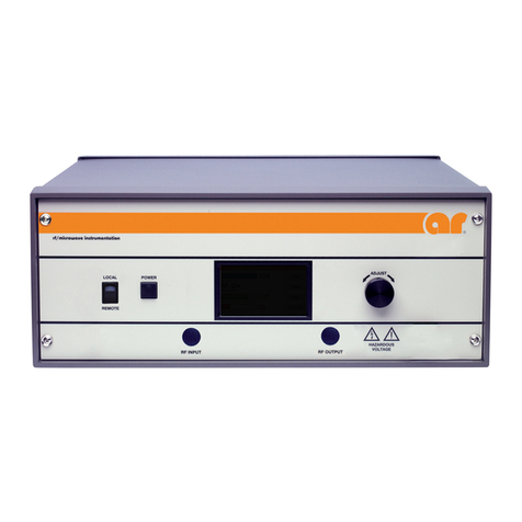
The Model 681 is a self-contained, broadband microwave amplifier designed for laboratory applications
where instantaneous bandwidth, high gain, and moderate power output are required. A GAIN control, which
is conveniently located on the unit’s front panel, can be used to decrease the amplifier’s gain by 20 decibels
(dB) or more. S olid state technology is used exclusively to offer significant advantages in reliability and
cost. A Model 681, used with a frequency-swept signal source, will provide rated power output from 0.7–4.2
gigahertz (GHz) (See Specification Sheet at the end of this section for more details). T ypical applications
include antenna and component testing, wattmeter calibration, and electromagnetic interference (EMI)
susceptibility testing, as well as usage as a d river for frequency multipliers and high-power amplifiers. The
Model 681 can be operated locally by using the unit’s front panel controls, or remotely by using the unit’s
IEEE-488, RS-232 interface, USB, or Ethernet interface.
Special features incorporated into the Model 681 include the following:
•A Digital Control Panel (DCP) that allows both local and remote (via a computer interface) control of
the amplifier (including adjustment of the amplifier’s RF Gain during CW mode operation) and provides
graphical displays of the amplifier’s Forward and Reflected power levels.
•RF output level protection.
•A General Purpose Interface Bus (GPIB)/IEEE-488.2 interface for remote control of the amplifier’s
operating functions.
•RS232 serial communications including both wire and fiber-optic ports for remote control.
•USB Communication port for remote control.
•Ethernet Communication port for remote control.
•Protection is provided by DC current limiting, over-temperature shut down and RF power limiting.
1.2 SPECIFICATIONS
Refer to the AR RF/Microwave Instrumentation Data Sheet at the end of this section for detailed
specifications.
1.3 POWER SUPPLIES
The Model 681 contains two switching power supplies. The input voltage range to the power supplies is 90–
264 VAC, 50-60Hz, selected automatically. T he AC input power, combined for these two supplies is
approximately 900 watts.
PS1 has a +5 volt, standby supply for the A22A1 Control/Fault board and the A23A1 Interface board used for
the remote interfaces. The +5 volt supply is also for operation of the A21 ALC board.
PS1 is a multiple output supply. The main +26.8V, 10A supplies voltage to the RF low level and the first
driver quad amp. The +24V, 7A is for operating the cooling fans and the –24 volts DC is supplied to the
(A20) Regulator board and the A1 preamplifier.
WARNING: EXPORT-CONTROLLED
Model 681
2 Rev A
PS2 is a single output supply. The main +26.8V, 27A supplies voltage to the RF final stages. Primary AC
circuit protection is provided by the circuit breaker in the Power Entry Module.
1.4 PROTECTION CIRCUITS
Features incorporated into this unit include RF output level protection circuits, thermal protection circuits,
and internal DC level sensing and monitoring circuits that sense the voltage on each of the final and driver
amplifier modules. There is protection for the AC main circuit. B oth switching supplies are short circuit
protected. Reaching a threshold of either of the RF forward (incident) or reverse (reflected) power limit
adjustments, which are adjusted to approximately 225 watts and 200 watts respectively, will initiate limiting,
or smooth drive level fold-back, in a low-level stage of the amplifier chain. If the limiting circuits cannot
keep the amplifier’s levels below the limit threshold, the protection circuits will invoke a shutdown of the
main power supplies and low-level driver in the amplifier. Power amplifier modules are monitored for both
over-current and under-current. A RESET function is provided to permit re-powering of the amplifier in case
of transient or temporary activation of the amplifier’s protection circuitry. The low-level driver and output
amplifier subassemblies are thermally monitored.
The digital control panel monitors all fault signals, stores and displays any that are invoked and asserts the
required action.
1.5 INSTALLATION
Before proceeding, thoroughly inspect the amplifier for signs of physical damage that may have been
incurred during shipment and completely read the following installation and operating instructions, paying
special attention to all CAUTION notes.
1.5.1 Location
Select an operating location that will permit air to circulate freely around the amplifier’s cabinet. T he
Model 681 utilizes air cooling and should be located where the normal flow of air into or exiting from the
unit will not be restricted, diverted, or re-circulated through the unit itself; in particular, the flow of warm air
exiting the rear of the amplifier should not be impeded.
Do not position the unit next to a wall or other equipment that would restrict the flow of air into the bottom
of the unit or out of the rear of the unit.
1.5.2 Power
The Model 681 is designed to operate using AC primary power of 90–264 Volts Alternating Current (VAC),
47–63 Hz single phase, 900 watts maximum.
CAUTION:
Dangerous voltages are present in the Model 681 whenever the unit is
plugged into an AC outlet. Always disconnect the unit from the main
power line when servicing it. Please note that neither the Keylock Switch
nor the POWER switch will completely shut off the unit’s AC power.
WARNING: EXPORT-CONTROLLED
Approved for public release by AR RF/Microwave Instrumentation 091212
160 School House Road Souderton, PA 18964-9990 • 215-723-8181 • www.arworld.us Page 1 of 2
Model 681, M1
180-200 Watts CW
0.7GHz–4.2GHz
The Model 681 is a portable, self-contained, air-cooled, broadband, completely solid-state amplifier designed for
applications where instantaneous bandwidth, high gain and linearity are required. Push-pull circuitry is utilized in all
high power stages in the interest of lowering distortion and improving stability. The Model 681, when used with a sweep
generator, will provide 180-200 watts minimum over frequency range.
The Model 681 is equipped with a Digital Control Panel (DCP) which provides both local and remote control of the
amplifier. The DCP uses a digital display, menu assigned softkeys, a single rotary knob, and four dedicated switches
(POWER, STANDBY, OPERATE and FAULT/RESET) to offer extensive control and status reporting capability. The display
provides operational presentation of Forward Power and Reflected Power plus control status and reports of internal
amplifier status. Special features include a gain control and RF output level protection.
All amplifier control functions and status indications are available remotely in GPIB/IEEE-488 format, RS232 hardwire
and fiber optic, USB and Ethernet. The buss interface connector is located on the back panel and positive control of local
or remote operation is assured by a keylock on the front panel of the amplifier.
The low level of spurious signals and linearity of the Model 681 make it ideal for use as a driver amplifier in testing
wireless and communication components and subsystems. It can be used as a test instrument covering multiple
frequency bands and is suitable for a variety of communication technologies such as CDMA, W-CDMA, TDMA, GSM etc.
It is also suitable for EMC Test applications where undistorted modulation envelopes are desired.
The export classification for this equipment is 3A001. These commodities, technology or software are controlled for
export in accordance with the U.S. Export Administration Regulations. Diversion contrary to U.S. law is prohibited.
120
130
140
150
160
170
180
190
200
210
220
230
240
250
260
270
280
Power (Watts)
Freq. (GHz)
MODEL681 TYPICALPOWEROUTPUT
P1dB
P3dB
Psat

Page 2 of 2
SPECIFICATIONS, 681
RATED POWER OUTPUT ...............................................200 watts typical
190 watts minimum, 0.7-3.0 GHz; 180 watts minimum, 3.0-4.2 GHz
200 watts minimum, 728–960 MHz
1475–1559 MHz
1805–1990 MHz
2010–2170 MHz
2570–2690 MHz
INPUT FOR RATED OUTPUT..........................................1.0 milliwatt maximum
POWER OUTPUT @ 3dB COMPRESSSION
Nominal ................................................................190 watts
Minimum ...............................................................160 watts minimum
POWER OUTPUT @ 1dB COMPRESSION
Nominal ................................................................165 watts
Minimum ...............................................................125 watts minimum
FLATNESS.....................................................................±1.5 dB typical
±2.0 dB maximum
FREQUENCY RESPONSE ...............................................0.7–4.2 GHz instantaneously
GAIN (at maximum setting) ...........................................52.6 dB minimum
GAIN ADJUSTMENT......................................................(Continuous Range), 15 dB minimum, (4096 steps remote)
INPUT IMPEDANCE.......................................................50 ohms, VSWR 2.0:1 maximum
RF POWER DISPLAY ......................................................0–250 Watts
OUTPUT IMPEDANCE ...................................................50 ohms, nominal
MISMATCH TOLERANCE...............................................100% of rated power without foldback. Will operate without damage or
oscillation with any magnitude and phase of source and load impedance. (See
Application Note #27)
MODULATION CAPABILITY...........................................Will faithfully reproduce AM, FM, or pulse modulation appearing on the input
signal
THIRD ORDER INTERCEPT .............................................60 dBm typical
HARMONIC DISTORTION.............................................Minus 20 dBc, maximum at 175 watts
SPURIOUS ....................................................................Minus 73 dBc typical.
PRIMARY POWER (Selected Automatically) ......................90-132, 180-264 VAC, 50/60 Hz, single phase, 1050 watts maximum
CONNECTORS
RF Input .................................................................N female, See Model Configurations
RF Output ..............................................................N female, See Model Configurations
REMOTE INTERFACES
IEEE-488.........................................................24 pin
RS-232 ...........................................................9 pin Subminiature D
RS-232(fiberoptic)..........................................Type ST
USB 2.0 ..........................................................Type B
Ethernet ..........................................................RJ-45
SAFETY INTERLOCK ......................................................15 pin Subminiature D
COOLING....................................................................Forced air (self contained fans)
Maximum Operating Temperature ..........................32°C
WEIGHT .......................................................................
34.5 kg (76 lbs)
SIZE (W x H x D)............................................................48.3 x 26.7 x 61cm (19.0 x 10.5 x 24in)
EXPORT CLASSIFICATION .............................................3A001
MODEL CONFIGURATIONS
Model RF Input Connector RF Output Connector
681 Front Panel Front Panel
681M1 Rear Panel Rear Panel

Rev A 5
2. OPERATING INSTRUCTIONS
2.1 GENERAL
Operation of the Model 681 broadband amplifier is quite simple. The amplifier’s input signal, whether swept
or fixed in frequency, is fed into the jack marked RF INPUT, and the amplifier’s output signal is taken from
the jack labeled RF OUTPUT. The unit is turned on by activating the front panel POWER switch. In the
event of a major malfunction, protection is provided by a circuit breaker located on the unit’s rear panel.
CAUTION:
The Model 681 Amplifier is typically not critical in regard to source and
load Voltage Standing Wave Ratio (VSWR) and will remain
unconditionally stable with any magnitude and phase of source and load
VSWR. However, placing the amplifier in the operate mode without a load
connected to the output connector is not recommended. It has also been
designed to withstand, without damage, RF input power levels up to
twenty (20) times its rated input of 1mW. However, signal levels higher
than 20mW or transients with high peak voltages can damage the
amplifier. Also, accidental connection of the Model 681’s output to its
input (either through direct connection or parasitic feedback paths) will
cause oscillations that may permanently damage the unit’s input
transistors.
The 681 Amplifier is protected from input overdrive by an automatic level control circuit which will limit the
maximum RF level to the first gain stage (U2) of the RF Amplifier to approximately 0 dB m. The 681 RF
power transistors are protected from over temperature by sensing the chassis temperature near the RF output
transistors. In the event of a cooling fan failure or an airflow blockage, the DC voltage will be removed from
the RF stages, when the chassis temperature reaches approximately 70°C.
Normal operation can be resumed after the chassis temperature drops below 70° C.
2.2 CONTROL AND INDICATOR FUNCTIONS
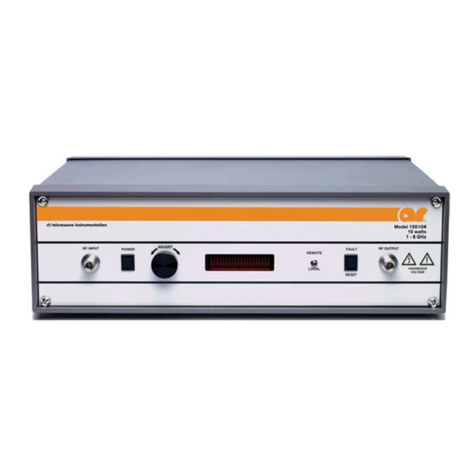
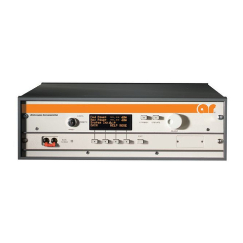
The Model 681’s front panel is shown in Figure 2-1; the unit’s rear panel features are detailed in Figure 2-2.
2.2.1 Keylock Switch
The Keylock Switch is provided for protection from unauthorized use or unexpected remote control of the
amplifier. The amplifier can only be turned on locally when the Keylock Switch is in the LOCAL position.
Likewise, the unit can only be turned on or controlled remotely when the Keylock Switch is in the REMOTE
position. P lacing the Keylock Switch in the INHIBIT position places the amplifier in the off mode and
prohibits any control of the amplifier.
WARNING: EXPORT-CONTROLLED
Model 681
6 Rev A
2.2.2 POWER Switch
The momentary POWER switch turns the main power to the amplifier on and off. The status of the green
light-emitting diode (LED) in the switch indicates whether the amplifier’s power is on or off. The main
power supply fans are active when power is on. The graphic display is active as long as the main power
circuit breaker of the amplifier power entry module is on.
1
2 3 4
5
6
7
8
9
10
11
Figure 2-1 Digital Control Panel (DCP) Features
Item Title Function
1 INHIBIT, LOCAL, REMOTE Keylock Switch, 3-position; key removal in INHIBIT position only
2 POWER POWER control with indicator LED
3 DISPLAY Numerous parameter values and fault messages
4 SOFT-KEYS Soft-keys 1–4 (#1 top, #4 bottom) (Function varies with menu)
5 ADJUST Adjust knob to change selected variables
6 RF ON/OFF RF Control button
7 USER Access User screen
8 BACK Returns user to previous menu
9 MAIN MENU Returns user to the main menu
10 RF INPUT Type N female connector
11 RF OUTPUT Type N female connector

Model 681
Rev A 7
2.2.3 Main Power
The Main Power circuit breaker is located on the rear panel of the amplifier.
Figure 2-2. Rear Panel Features
2.2.4 RF ON/OFF
The RF ON/OFF button toggles the amplifier from a Standby to an Operate mode. The status of the function
is indicated on t he display as RF ON or RF OFF. In the RF ON state, RF output is enabled according to
control settings and amplifier RF input. Main cooling fans will operate. In the RF OFF state, there will be
no RF output.
2.2.5 RESET Function (Soft Key)
The RESET function is a soft key menu selection that will cause the amplifier to attempt to reset. Selecting
Reset may clear the fault, depending upon the type of fault that has occurred. If the amplifier is in an over-
driven condition, lowering the amplifier’s gain or RF input level should enable the function to reset the
amplifier.
WARNING: EXPORT-CONTROLLED

Model 681
8 Rev A
2.3 DIGITAL CONTROL PANEL (DCP) OPERATIONS
The operations described in this section assume that the user is performing these operations from the
amplifier’s front panel with the Keylock Switch in the LOCAL position. Computer access to command and
status functions is also available when the Keylock Switch is set to REMOTE. Refer to section 2.5.5 for
information on remote operation.
Amplifier functions are visually monitored on the front panel display. POWER is controlled by a dedicated
push-button switch to the left of the display. The safety Keylock Switch is located to the lower left of the
display.
To the immediate right of the display are eight buttons in two columns. The four buttons in the right column
are dedicated functions. The MAIN MENU sets the panel display and the associated circuitry to control the
most basic functions of the amplifier, as identified on the display. The BACK button is for navigation within
the various menus presented on the display, changing the display to the previously shown menu. The USER
button initiates a set of menus used to set up various control functions. The RF ON/OFF button causes the
power amplifier sections to produce RF output power from the rear output connector, based on the various
settings and the input level to the amplifier. The main amplifier fans will be heard when this function is
active. The four buttons in the left column are soft keys whose function changes according to the menu
choices on the display to their immediate left.
To the far right is an ADJUST knob. This knob is used to adjust most of the variables shown on the display.
Many variables can also be fine-adjusted by soft keys when corresponding up/down arrows appear on the
display.
The display is active and illuminated whenever A.C. power is supplied to the unit and the main circuit
breaker is on.
Each menu display is arranged according to a si milar pattern. To the right of the display a label is shown
which is used to designate both the name of the adjacent soft-key and the variable that is being adjusted.
Most displays include the Forward and Reflected power levels on the two bottom-most lines of the display.
These indications are developed using a dual-directional coupler located within the amplifier near the RF
output port, and should be used as uncalibrated indicators of approximate power level.
General Display Navigation is shown in Figure 2-3, LCD Soft Key Screens.
WARNING: EXPORT-CONTROLLED
Model 681
Rev A 9
Figure 2-3. LCD Soft-Key Screens
WARNING: EXPORT-CONTROLLED
Model 681
10 Rev A
2.3.1 RF GAIN Control
The RF GAIN control, which has a minimum of 15dB of range, is used to adjust the input attenuator of the
preamplifier-leveler module. This control simply adjusts the output power level for a fixed input power
level.
To adjust the RF Gain, press the RF GAIN soft-key. A djust the value using the adjust knob or the
UP/DOWN scroll keys. Please note that the display panel is limited in resolution compared to the control
signals, which are generated and sent to the leveler electronics module. A quick press of the UP or DOWN
keys that may not show any change on the display may, in fact, cause very small, precise changes in the
amplifier’s RF output.
2.4 INPUTS AND OUTPUTS
The input and output connectors described in the following sections are located on the unit’s front or rear
panels; refer to the Front and Rear Panel Features drawings (Figure 2-1, Figure 2-2).
2.4.1 RF Input
This Type N connector is the RF input to the amplifier. It should be connected to a RF signal generator or
sweep generator.
2.4.2 RF Output
This Type N connector is the RF output of the amplifier.
CAUTION:
Do not connect or disconnect any loads or cables from the amplifier’s RF
Output when the amplifier is in the Operate mode. Dangerous voltages
that could cause serious injury to the user exist at the RF Output when
the amplifier is under power.
2.4.3 IEEE-488, USB, and RS-232 Interfaces
The Model 681’s remote interfaces allow remote control, via a computer, of all amplifier functions (except
for the Keylock Switch position) that can be controlled from the front panel. When the amplifier is in the
Remote mode (as determined by the position of the Keylock Switch), a special Remote display is shown (see
Figure 2-3). Front panel controls are deactivated, except for the Keylock Switch, which can be rotated to
LOCAL or INHIBIT in order to prevent remote control commands from being executed.
Refer to section 2.6 for information on remote operation of the amplifier.
WARNING: EXPORT-CONTROLLED
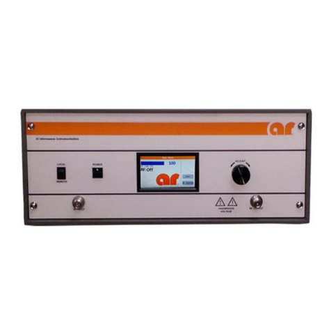
Table of contents
Other AR Amplifier manuals

AR
AR AA26G40-20 Service manual

AR
AR 750W1000B Series Service manual

AR
AR 500T2G8 Service manual

AR
AR 500A250D Service manual

AR
AR AA18G26-20 Service manual

AR
AR 500S1G2z5A Service manual

AR
AR 150W1000B Service manual

AR
AR 40S6G18-L Service manual

AR
AR 250U1000 Service manual

AR
AR 800A3B Series Service manual