arboga E 308 User manual

ARBOGA
Industrivej 3-9 · DK-9460 BROVST · DENMARK
TEL.: +45 98 23 60 88 · FAX: +45 98 23 61 44
Manual
E 308 - EP 308 –EPB 308 –POP 308
Industrial grinding machine

2
EC declaration of conformity
hereby declares that
ARBOGA Double Ended Grinders are manufactured in accordance with the provisions
of the European Parliament and Council Directive 2006/42 / EC of 17 May 2006
And also in accordance with:
•Low Voltage
•EUROPEAN PARLIAMENT AND COUNCIL DIRECTIVE 2014/35 / EU of
26 February 2014
•EMC
•EUROPEAN PARLIAMENT AND COUNCIL DIRECTIVE 2014/30 / EU of
26 February 2014
ARBOGA A/S
Industrivej 3-9
DK-9460 Brovst, Denmark
www.scantool-group.com
Tel. + 45 98 23 60 88
Fax: + 45 98 23 61 44

3
Table of Content
1. TRANSPORT & HANDLING 4
1.1 TRANSPORT 4
1.2 HANDLING 4
1.3 PLACING 4
2. OPERATOR’S GUIDE 5
2.1 OPERATION 5
2.2SAFETY RULES FOR STATIONARY POWER TOOLS. 5
2.3 MAINTENANCE 7
3. BELT ARM 8
3.1 ASSEMBLING AND MOUNTING OF THE BELT ARM 8
3.2 CHANGING THE GRINDING BELT 9
3.3 MAINTENANCE OF BELT ARM 10
3.4 OPERATING THE BELT ARM 10
4. POLISHING MACHINE 11
4.1 ADJUSTMENT THE POLISHING MACHINE. 11
5. KU 8-EXHAUST SYSTEM 12
5.1 ASSEMBLING AND MOUNTING OF KU 8-EXHAUST SYSTEM 12
5.2 MAINTENANCE OF THE KU 8-EXHAUST SYSTEM 12
6. SPARE PARTS 13
6.1 MACHINE VIEW OF E308 13
6.2 E308 BASIC MODEL 14
6.3 E308 COVER 15
6.4 E308 BELT ARM 17
6.5 KU 8-EXHAUST SYSTEM FOR E308 19
6.6 EX-16-EXHAUST UNIT FOR EPX 308 21
6.7 POP 308 W/SPINDLE 22
6.8 POP 308 W/FLANGE 23
7. TECHNICAL DATA 24
7.1 TECHNICAL SPECIFICATIONS 24
7.2 DIMENSIONS 24
7.2 WIRING DIAGRAM 25
7.3 DISASWITCH W/EMERGENCYSTOP 26
7.4 GUARANTEE 26

4
1. Transport & handling
1.1 Transport
E 308 Industrial grinding machine is delivered mounted to a pallet wrapped in protective
packing.
1.2 Handling
E 308 industrial grinding machine can easily be transported in the packing in which it is
delivered. If the grinding machine is delivered on a pedestal you must make sure that the
pedestal is secured to the transport pallet.
1.3 Placing
Placing of the industrial grinding machine must take place on a firm and level surface.
Now tighten the grinding machine to the floor or the working table by using the four bolt
holes used for securing the machine to the pallet.
The electrical voltage must be within the given ranges shown on the motor label.
The machine must be wired according to the wiring diagram (please see section 7.3).
The wiring must be performed by an authorised installer. Please make sure that the motor
has the correct direction of rotation (please see the arrow on the cover).
Fig.: 1.1
Before operating the machine please control that the outer cover (A) (see fig.: 1.1) is
secured to the inner cover. The outer cover must be mounted during use of the machine
and can only be dismounted during maintenance. The grinding wheel (B) must be able to
rotate freely without being loose. The tool rest (C) must be adjusted to a distance of appr.
2mm from the grinding wheel.
The eye shield (D) must be kept clean and adjusted to the correct position and the spark
arrester (E) must also be adjusted to a distance of 5mm from the grinding wheel and
lightly fastened.
All these checks and adjustments can only be made while the machine is disconnected
from the power source. First time you start up the machine please let it run at maximum
speed for appr. 5 minutes before start grinding. Make sure you are positioned in a safe
distance while doing the running test.

5
2. Operator’s guide
2.1 Operation
After adjustment and connection of the grinding machine it is ready for use. Lead the work
piece to the grinding wheel with a firm and level pressure to avoid destroying the grinding
wheel and overloading the motor. Avoid excessive pressure or uneven grinding. Let the
machine run at max speed before start grinding. Grind at max speed if possible. Clamp
the work piece if possible as this is safer than holding the work piece in your hands.
Avoid grinding on the side of the grinding wheel unless you grind on a cup wheel.
Do not stop the rotation of the grinding wheel by pressing the work piece against it. Let the
grinding wheel stop by itself. It is important to have the work place well-lighted.
2.2 Safety rules for stationary power tools.
Follow them to achieve best results and full benefit from your new
machine
The very good craftsman respects the tools with
which he works. He knows they represent years
of constantly improved design. He also knows
that they are dangerous if misused.
This is the theme of a new safe-use program for
stationary power tools. The safety rules are
based on approved practices in industrial and
home shops.
1. Know your power tool. Read
the owner’s manual carefully.
Learn its applications and
limitations, as well as the
specific potential hazards
peculiar to this tool.
2. Keep guard in place
and in working order.
3. Ground all tools. If tool is equipped
with three-prong plug, it should be
plugged into a three-hole electrical
receptacle. If an adapter is used to
accomodate a two-prong receptacle,
the adapter wire must be attached to
a known ground. Never remove the
third prong.
4. Remove adjusting keys
and wrenches. Form habit of
checking to see that keys
and adjusting wrenches is
removed before turning it on.
5. Keep work area clean.
Cluttered areas and benches
invite accidents.
6. Avoid dangerous
environment. Don’t use
power tools in damp or wet
locations or expose them to
rain. Keep your work area
well lighted.
7. Keep children away. All
visitors should be kept in a
safe distance from work
area.
8. Make workshop kidproof with
padlocks, master switches, or by
removing starter keys.

6
9. Don’t force tool. It will do the job
better and be safer at the rate for
which it was designed.
10. Use right tool. Don’t force
tool or attachment to do a job it
was not designed for.
11. Wear proper apparel. Wear no
loose clothing, gloves, neckties,
rings, bracelets, or other jewelry
which may get caught in moving
parts. Non-slip footwear is
recommended. Wear protective
hair covering to contain long hair.
12. Always use safety
glasses. Also use face or
dust mask if cutting
operation is dusty. Everyday
eyeglasses only have impact
resistant lenses. They are
NOT safety glasses.
13. Secure works. Use clamps
or vise to hold works, when
pratical. It’s safer than using
your hands and it frees both
hands to operate tool.
14. Don’t overreach. Keep proper
footing and balance at all times.
16. Disconnect tools before servicing and when
changing accessories such as grinding wheels,
polishing mops, grinding belts, blades, bits,
cutters, etc.
18. Use recommended accessories.
Consult owner’s manual for
recommended accessories. Use of
improper accessories may cause risk
of injury to persons.
17. Reduce the risk of
unintentional starting. Make sure
switch is in off position before
plugging in.
15. Maintain tools with
care. Keep tools sharp and
clean for best and safest
performance. Follow
instructions for lubricating
and changing accessories.

7
2.3 Maintenance
The grinding machine must be placed on a dry place to avoid the grinding wheels
from getting wet by damp or rain.
The grinding wheel often gets uneven during use and therefore we recommend
that you make it even occasionally. We recommend that you replace the grinding
wheel when it is worn about 25%. An uneven grinding wheel causes vibrations
which with time destroys the bearings in the machine.
Damaged tool rests, eye shields and covers must be replaced immediately to
avoid personal injuries or material damage.
When the grinding wheel must be replaced first dismount the spark arrester (A)
(see fig.: 2.1), then dismount the outer cover (B). The nut (C) is unscrewed and
now the outer flange and the grinding wheel can be taken off. The new grinding
wheel is not allowed to exceed the measures given on the motor sign on the
machine. It is very important that the hole dimension is correct.
The grinding wheels are supplied with labels (discs made of pressed material),
which are placed around the holes on both sides of the grinding wheel. If these
labels are damaged or missing they must be replaced by new ones of the same
dimension.
The new grinding wheel is mounted between the two flanges (D) and the lock nut
(C) is screwed on and tightened. The lock nut (C) must be tightened enough to
hold tight the grinding wheel but not too tight as this will result in unwanted tension
in the grinding wheel.
Fig.: 2.1
8
3. Belt arm
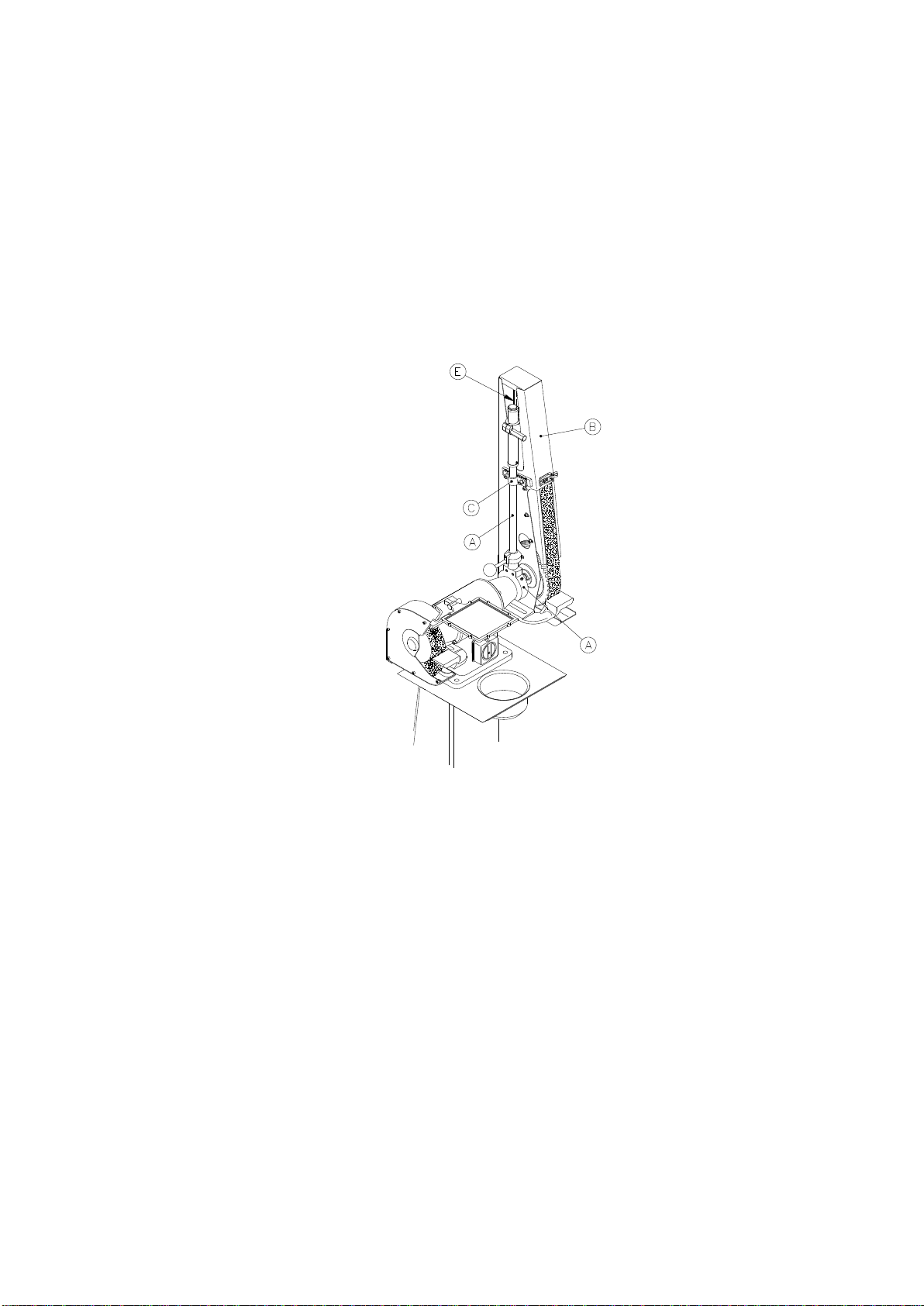
3.1 Assembling and mounting of the belt arm
If the grinding machine is equipped with a grinding cover or a trimming cover,
these must be dismounted completely before mounting the belt arm.
Mount the telescope arm (A) to the cover (B) by using the fittings for the telescope
arm (C) and by securing the cover (B) by screwing a screw through the side plate
into the holder for the telescope arm (D). The top roll (E) must be inside the cover
(B).
Fig.: 3.1
The fittings for the telescope arm (C) may not be tightened more than it is still
possible to adjust the direction of rotation of the grinding belt.
The belt arm can be adjusted to the wanted inclination and then the holder for the
telescope arm (D) must be tightened by tightening the two screws placed in the
ring on the holder.
The flanges, contact wheel and the lock nut is mounted (see split drawing of the
belt arm for order). Please control that the top roll (E) and the contact wheel run
parallel. The position of the contact wheel can be adjusted by using the enclosed
distance rings.
The top roll (E) can be loosened and adjusted to the wanted grinding belt length.
In the same way you can tighten the grinding belt.

9
3.2 Changing the grinding belt
When the grinding belt is worn out it must be replaced which is done as follows:
Open the lid plate (A) (see fig.: 3.2) on the cover and pull down the handle (B).
This way the grinding belt (C) will be loosened, and now it can be dismounted and
replaced by a new belt in reverse order. Control that the arrows at the back of the
grinding belt correspond to the direction of rotation. When the new grinding belt is
mounted it is necessary to adjust so that the grinding belt runs straight. This is
done by using the handle (D), which is loosened so the telescope arm (E) and the
top roll (F) can be turned along until the grinding belt runs straight. Now tighten the
handle (D).
This adjustment of the grinding belt may only be performed by pulling the
grinding belt with your hands and with the POWER OFF.
Fig.: 3.2
There are many kinds of grinding belts and therefore it is very important to choose
the correct type of grinding belt. You need to consider the material, grit size,
grinding belt material and glue.
In this connection we can inform that there are different kinds of contact wheels
with various softness and shapes for different purposes.

10
3.3 Maintenance of belt arm
Empty the spark arrester (A) regularly (see fig.: 3.3) to prevent warm sparks in
destroying or deforming grinding belts or contact wheel. If the machine is
equipped with a VFCB-exhaust system please control if the suction hoses need
cleaning. The dust bag must be emptied or changed whenever necessary. The
contact wheel (B) should be changed when the edges have been worn round or if
the lane is defective. Change the graphite pad (C) on the grinding surface when
needed.
Fig.: 3.3
When changing the contact wheel first dismount the grinding belt (D), as
described above.
The nut (E) is unscrewed and the flange (F) is taken off together with the contact
wheel (B). Mount the new contact wheel (B) in reverse order.
3.4 Operating the belt arm
Grinding on the belt arm can be done at the contact wheel or on the grinding
surface. It is also possible to dismount the grinding surface and grind freely on the
grinding belt. Lead the work piece slowly towards the grinding belt and avoid
uneven grinding to prevent destroying the grinding belt or overloading the motor.

11
4. Polishing machine
4.1 Adjustment the polishing machine.
Placing of the machine must take place on a firm and level surface. Now secure
the polishing machine to the work table or the floor by using the four holes in the
base used for mounting the machine to the pallet.
Please wire the machine according to the given voltages stated in this manual and
on the motor sign. Check for correct direction of rotation on the motor. All wiring
must be performec by an authorized electrician.
Fig.: 4.1
Before start operating please check if the polishing discs (A) (see fig.: 5.1) are
firmly secured to the rotor. The polishing disc is mounted when the machine is
disconnected. The polishing disc (A) must rotate freely without being loose.
Checks and adjustments are only to be performed when the machine is
disconnected.
Make sure to be in a safe distance from the machine while it is running for the first
time.

12
5. KU 8-exhaust system
5.1 Assembling and mounting of KU 8-exhaust system
The following description on assembling and mounting of KU 8-exhaust system is
valid for whether it is a KU 8 or if it is a VFCB-121. The mounting order is the
same for both models.
The clamp (A) (see fig.: 4.1) is first mounted at the back of the E 308 and then as
shown on the KU 8-motor. Dismount the blind stop at the back of the E 308 and
mount the connector (B). Dismount the switch on the E 308 without unscrewing
the wires. Lead the wire (C) through the connector (B) and screw the protection
hose (D) onto the connector (B). Mount the wires from the KU 8-exhaust system
on the switch (see wiring diagram). Mount switch again. Dismount the blind stops
on the cover or the belt arm and instead mount the lid (E) with the exhaust
connecting pipe. To the last fit the suction hoses (G) and mount them with the
straps (H).
Before use the KU 8-exhaust system must be mounted with suction hoses on the
exhaust connecting pipe (I), which then is connected to the central exhaust
system. If the central exhaust system is not connected to a cyclone the exhaust
from the KU 8-exhaust system must be connected to a cyclone and then
connected to the central exhaust system. If there is no central exhaust system
dust bags (J) must be mounted on the exhaust connecting pipe (I).
In case the KU 8-exhaust system is mounted on a E 308 double grinder the cast
bends (K) can be used to mount the KU 8-exhaust system to the grinding machine
so that the clamp (A) and the suction hoses (G) with accessories can be left out.
Fig.: 5.1
5.2 Maintenance of the KU 8-exhaust system
Nothing on the KU 8-exhaust system needs maintenance except for it is
necessary regularly to check that the suction hoses are in goods condition and
that the channels are free of grinding dust.

13
6. Spare parts
6.1 Machine view of E 308
In the following we have illustrated split drawings and spare parts lists.
Fig.: 6.1 (A) Motor part, (B) Grinding cover, (C) Belt arm, (D) KU 8-exhaust system.
14
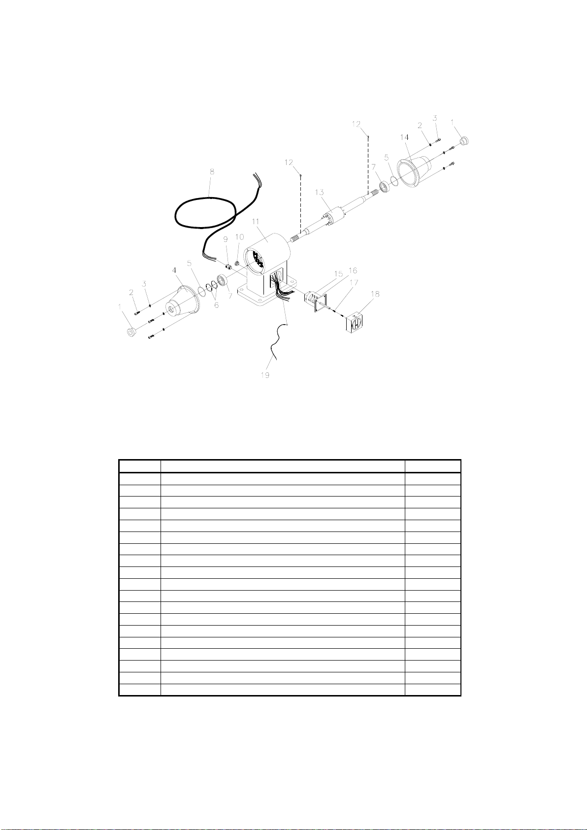
6.2 E 308 basic model
Fig.: 6.2 Split drawing of E 308 basic model
6.2.1 Spare parts list for E 308
Pos.no.
Description
Item No.
1
Collar bushing E 308
0995681
2
Screw M6x20 CH Z
0331686
3
Spring disc DIM 6 Z
1323060
4
Bearing end shield V
0187860
5
O-ring 50x45x3 mm
1385259
6
Wave spring 50x44x0.6
0100331
7
Bearing 6205 2Z/C3
0104221
8
Cable 4x0.75mm² sort
0129420
9
Cable lead-in PG11
0105154
10
Blind stop PG11
2112512
11
Stator housing
1313700
12
Split pin ø4x8
0711179
13
Rotor cpl.
0766917
14
Bearing end shield H
1461142
15
DISA switch 230 V
0188807
16
DISA switch 440 V
0188814
17
Skrew M4x10
0100427
18
Switch for DISA switch
0110049
19
Earth cable
1461327

15
6.3 E 308 cover
Fig.: 6.3 Split drawing of E 308 cover

16
6.3.1 Spare parts list for E 308 cover
Pos.no.
Description
Cover
LEFT
Cover
RIGHT
1
Machine screw M4x10 CHJ Z
0100425
0100425
2
Frame f/ eye shield
0111807
0111807
3
Rubber disc ARBOGA eye shield
0112535
0112535
4
Glass 150x150x6mm LEXAN clear
0110389
0110389
5
Wing nut M6 DIN 315
0741663
0741663
6
Disc ø6.4x11x1.6 DIN 433
0737631
0737631
7
Holder f/frame f/eye shield
0111808
0111808
8
Frame w/holder
0111806
0111806
9
Machine screw M6x30
0331694
0331694
10
Nut M 5
0207927
0207927
11
Bend for ARBOGA eye shield
0110012
0110012
12
Auto disc ø5.2x12.7x0.8
0112700
0112700
13
Shaft f/eye shield ARBOGA
0114351
0114351
14
Clamp for eye shield new model
0110010
0110010
15
Spring 5x10mm
0112911
0112911
16
Machine screw M5x25 PHJX Z
0112732
0112732
17
Screw M5x10 CH Z
0120628
0120628
18
Spring disc DIM 5 Z
0102555
0102555
19
Lock nut M8
0928640
0928640
20
Mounting plate f/cover ARBOGA 308
0318522
0318522
21
Cover ARBOGA 308, ext.
1003109
1003110
22
NutM20x1.5
0744824
0744816
23
Flange ext.
1105183
1105183
24
Pap labels
0920080
0920080
25
Grinding wheel 200x38x20 NK 60
1100329
1100328
26
Flange int.
0921572
0921572
27
Cover ARBOGA 308. int.
1003009
1003010
28
Screw M8x25 Steel set screw
0920025
0920025
29
Fittings f/cover 308
0114974
0114974
30
Holder f/spark arrester
0725719
0725719
31
Tool rest
0744409
0744425
32
Disc 3/8” Z
0101491
0101491
33
Screw M10x30 Z
0120707
0120707

17
6.4 E 308 belt arm
Fig.: 6.4 Split drawing of E 308 belt arm

18
6.4.1 Spare parts list for E 308 belt arm
Order number
Pos. No.
Description
RIGHT
LEFT
1
Top screw
2078212
2078212
2
Adjusting pipe for belt frame
9480687
9480687
3
Machine screw M4x4 Z
0737618
0737618
4
Lock ring DIM 42, DIN 472
7655123
7655123
5
Bearing 6302 2Z
1462846
1462846
6
Distance pipe ø22/15x10
2155002
2155002
7
Top roll
9480681
9480681
8
Shaft for top roll
2078200
2078200
9
Disc for top roll
9480693
9480693
10
Screw M6x16 CH Z low headed
3316860
3316860
11
Pointed screw M5x10
0737605
0737605
12
Holder for top roll
9480679
9480679
13
Spring for telescope arm
9480694
9480694
14
Pipe for telescope arm
9480682
9480682
15
Spring holder for telescope arm
2078202
2078202
16
Belt release handle M8x30
2078204
2078204
17
Pipe bushing for telescope arm
2078206
2078206
18
Pipe holder for telescope arm
9480692
9480692
19
Split pin ø5x25
2078208
2078208
20
Handle for belt adjustment
2188010
2188010
21
Fittings for telescope arm
1533813
1533813
22
Spring disc DIM 8 Z
0132594
0132594
23
Screw M8x25 CH Z
0120620
0120620
24
Middle ring
4318001
4318001
25
Pointed screw M8x16
2078210
2078210
26
Holder for telescope arm
2078211
2078211
27
Tool rest
0744425
0744409
28
Disc 3/8” Z
0101491
0101491
29
Screw M10x30 Z
0120707
0120707
30
Cover box for belt arm
1533780
1533781
31
Spring disc DIM 5 Z
0102555
0102555
32
Screw M5x10 CH Z
0120628
0120628
33
Felt packing
1533816
1533816
34
Cover plate
1533812
1533812
35
Distance ring ø30/20x6mm
1551176
1551176
36
Collar bushing E 308
0995681
0995681
37
Star handle ø40 M8 DIN 6335
1443593
1443593
38
Auto disc 5/16” Z
0132310
0132310
39
Spark arrester
1533808
1533808
40
Nut M5 Z
0737623
0737623
41
Flange int.
0921572
0921572
42
Contact wheel 200x50x20
1532170
1532170
43
Plan table
1533807
1533818
44
Flange ext.
1105183
1105183
45
Tap
2004899
2004899
46
Graphite pad 50x270
2004898
2004898
47
Nut M20x1.5
0744824
0744816
48
Grinding belt 50x1600 K80
0215080
0215080
49
Screw M8x16 Z
0120510
0120510
50
DN-Bearing ring for belt arm
0747329
0747329

19
6.5 KU 8-exhaust system for E 308
Fig.: 6.5 Split drawing of KU 8-exhaust system for E 308

20
6.5.1 Spare parts list for KU 8-exhaust system for E 308
Pos.no.
Description
KU 8
KU 8-121
1
Fan house LEFT ext.
0781266
0781266
2
Screw M5x16 CH Z
0120626
0120626
3
Spring disc DIM 5 Z
0102555
0102555
4
Screw ø5.5x26,5x2.5
0920026
0920026
5
Fan wheel KU 8 alu.
0995703
0995703
6
Screw M6x16 Z
0110134
0110134
7
Spring disc DIM 6 Z
1323060
1323060
8
Fan housing LEFT int.
0785628
0785628
9
V-Ring 16A
0654329
0654329
10
Feather 5x5x14
0100609
0100609
11
Screw M8x16 Z
0120510
0120510
12
Auto disc 5/16” Z
0132310
0132310
13
Clamp for KU 8 holder
1065297
1065297
14
Fan housing RIGHT int.
0781258
0781258
15
Fan housing RIGHT ext.
0785636
0785636
16
Electric motor
1043072
1043064
17
Threaded rod PG11
0920011
0920011
18
Protection hose 18x13 400mm
0920400
0920400
19
Dust bag
0811793
0811793
20
Screw M4x16 m/pan headed
2006480
2006480
21
Cork washer 120x9
2006728
2006728
22
Exhaust connecting pipe
1444190
1444190
23
Screw M5x10 CH Z
0120628
0120628
24
Spring disc DIM 5 Z
0102555
0102555
25
Strap 68/85
1944266
1944266
26
Suction hose
2006731
2006731
27
Exhaust connecting pipe
0318525
0318525
29
Bend for KU 8 left
0111729
0111729
29
Bend for KU 8 right
0111730
0111730
30
Pedestal for E 308
1065550
1065550
31
Table E 308*
0771317
0771317
32
Water cup
0771333
0771333
33
Disc ø13x24x2.5
0101494
0101494
34
Screw M12x40 Z
0120839
0120839
35
Union
0820210
0820210
* Table for E 308 w/belt arm or trimmer has no.: 0771316
This manual suits for next models
3
Table of contents


