Felker ST15E Use and care manual

OPERATING INSTRUCTIONS AND PARTS LIST
INSTRUCCIONES DE OPERACION Y LISTA DE PIEZAS
Surface Trac Grinder
Electric & Gasoline Models
MODELS: ST15E (1-1/2 HP Electric)
ST11H (11 HP Honda Gasoline)
Effective With Serial No. 308084 and Later
Model: _____________
Serial Number: _______________
Engine / Motor Serial No.: _______________
Purchase Date: _______________
0AF04087
© October 3, 2000
Printed in U.S.A.
Corporate Office
17400 West 119th Street
Olathe, Kansas 66061, USA
Western Division Center
17311 South Edwards Road
Cerritos, CA 90703-2427
Customer Service .............800-365-4003
Corporate. Office ............. 913-928-1000
Customer Service-FAX .... 800-825-0028
Corporate Office FAX ...... 913-438-7951

2
BEFORE YOU BEGIN: Read and understand all warnings and instructions before operating the Machine described in
this manual. WARNINGS AND CAUTIONS IN THIS MANUAL MUST BE UNDERSTOOD AND FOLLOWED!
FAILURE TO OBEY WARNINGS MAY RESULT IN SERIOUS INJURY OR DEATH. IT IS YOUR RESPONSIBILITY
to make sure persons who use this machine have read this manual.
CONTENTS Page
Symbol Definitions (English & Spanish)............................................................................................. 3 - 4
Hearing Hazard Warnings (English & Spanish)................................................................................. 5
Decals -Descriptions and Locations (English & Spanish).................................................................. 6
Figures: FIG. 1 - FIG. 33 (English and Spanish)................................................................................ 7 - 10
Parts Identification (English and Spanish) ......................................................................................... 11
English Language Section:
SAFETY WARNINGS - DO’s & DO NOT’s..................................................................................... 12 - 13
Specifications & Power Sources..................................................................................................... 14
Unit Dimensions.............................................................................................................................. 15
Tool Application Guide.................................................................................................................... 16
Pre-Operation Checklist & Scheduled Maintenance Quick Reference........................................... 17
English Instructions:
1 - Features, 2 - Assembly.................................................................................................... 18
3 - Check before Operating................................................................................................... 18 - 20
4 - Tool Installation................................................................................................................ 20 - 22
5 - Operating Instructions...................................................................................................... 22 - 23
6 - Incidents During Operation.............................................................................................. 23
7 - Maintenance .................................................................................................................... 23 - 24
8 - V-Belt Tension ................................................................................................................. 24
9 - Important Advise.............................................................................................................. 24 - 25
10 - Accessories, 11 - Repairs, 12 - Spare Parts................................................................ 25 - 26
Spanish Language Section (Not Available at This Time)................................................................... xx - xx
Parts List: Figures 1 - 14 (Text In English Only) ................................................................................ 27 - 49
Wiring Diagram for 1.5 hp Electric Model –Diagram 14 (Text In English Only)................................ 49

3
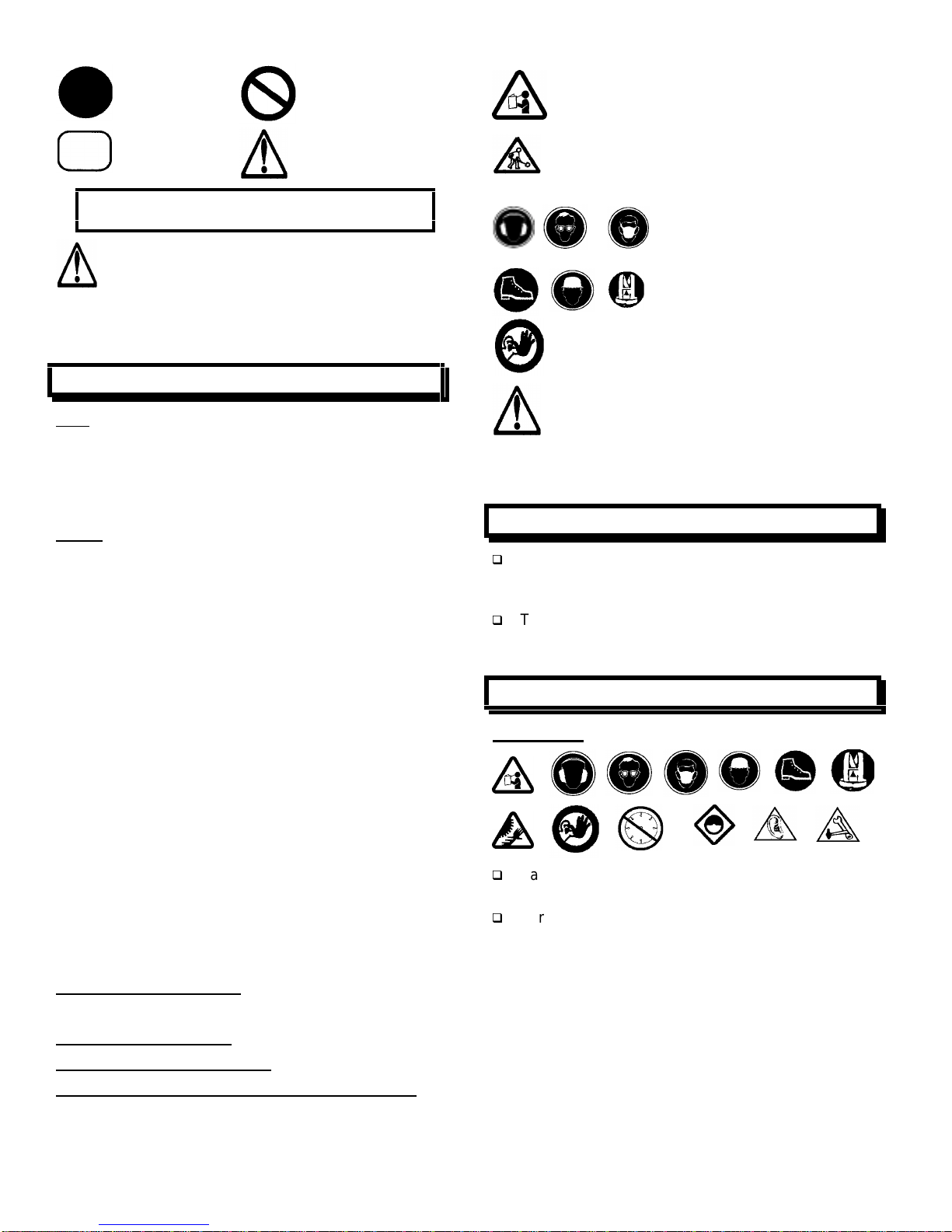
SYMBOL DEFINITIONS
DEFINICIÓN DE SIMBOLOS
____________________________________________________________________________________________
•Please read the instructions for use prior to operating the machine for the first time.
•Antes de la puesta en marcha, lea detenidamente las instrucciones y familiaricese con la máquina.
•Mandatory
•Obligatorio
•Indication
•Indicación
•Prohibition
•Prohibición
•Warning Triangle
•Triángwulo De Advertencia
•Wear Eye Protection
•Usar Gafas De Protección
•Wear Head Protection
•Usar Casco De Protección
•Wear Breathing Protection
•Usar Máscara De Protección
•The Use Of Ear Protection Is Mandatory
•Es Obligatorio El Uso De Protección Auditiva
•Wear Safety Shoes
•Usar Zapatos De Seguridad
•Wear Appropriate Clothing
•Usar Ropa Adecuada
•Motor Off
•Parar El Motor
•Use In Well Ventilated Area
•Usar En Una Área Bien Ventilada
•Do Not Use In Flammable Areas
•No Usar In Áreas Inflamables
•Machinery Hazard, Keep Hands And Feet Clear.
•Máquina Peligrosa - Mantenga Manos Y Pies Alejados De La Máquina

4
•Danger, Poison Exhaust Gas
•Peligro, Gases De Escape Tóxicos
•No Non-working Personnel In Area
•Prohibido Para Personas Ajenas A La Obra
•No Smoking
•No Fumar
•Do Not Operate Without All Guards In Place
•No Operar Sin Todas Las Protecciones In Su Sitio
•Always Keep the Blade Guards In Place
•Mantenga Siempre Las Protecciones De La Hoja En Su Sitio
•Keep Work Area Clean/Well Lit, Remove All Safety Hazards
•Mantenga Limpio El Sitio De Trabajo/Bien Iluminado, Elimine Todos Los Riesgos De Seguridad
•Dangerously High Noise Level
•Nivel De Ruido Elevadamente Peligroso
•Pay Extreme Attention To The Care And Protection Of The Machine Before Starting Up
•Ponga Extrema Atención Al Cuidado Y Preparación De La Máquina Antes De Ponerla En Marcha
•Remove Tools From Area and Machine
•Elimine Las Herramientas Del Área Y De La Máquina
•Oil Required
•Necesita Aceite
•Dipstick, Maintain Proper Oil Level
•Varilla De Control, Mantenga El Nivel De Aceite Correcto
•Lubrication Point
•Punto De Lubrication
•Unleaded Fuel Only
•Solamente Combustible Sin Plomo
•Repairs Are To Be Done By An Authorized Dealer Only
•Las Reparaciones Deben Ser Efectuadas Únicamente Por Un Distribuidor Autorizado
•Diamond Blade
•Sierra Diamantada
•Blade Diameter
•Diámetro De La Hoja

5
WARNING
HEARING HAZARD
DURING NORMAL USE OF THIS MACHINE, OPERATOR MAY BE EXPOSED TO A NOISE
LEVEL EQUAL OR SUPERIOR TO 85 dB (A)
ATENCION
RIESGO DE DAÑO AUDITIVO
EN CONDICIONES NORMALES DE UTILIZACIÓN, EL OPERADOR DE ESTA MÁQUINA PUEDE
ESTAR EXPUESTO A UN NIVEL DE RUIDO IGUAL O SUPERIOR A 85 dB (A)

6
DECAL DESCRIPTIONS AND LOCATIONS
DESCRIPCIÓN DE CALCAMONIAS Y UBICACIONES
P/N: 187053
Decal: Surface Trac Grinder
Location: Handle Sides (2)
Top of Adjustable Handle (1)
Quantity: 3 (All Models)
P/N: 177857
Decal, Operating Instructions
Location: Top Of Adjustable Handle
Quantity: 1 (All Models)
P/N: 187052
Decal, Felker (Since 1924)
Location: Front Of Gearbox Cover (1),
Rear Of Adjustable Handle (1)
Quantity: 2 (All Models) P/N:169065
Decal, Muffler Hot
Location: On Engine
Quantity: 1(Gasoline Model)
P/N: 176223
Decal, Warning
Location: On Frame Behind Front Shield (1),
Under Gearbox Cover On Top Of Gearbox (1)
Quantity: 2 (All Models)

Figures / Figuras
J
V1
PP
QQ 1 V1
LH
FIG. 2
A
C
FIG. 1
RH
F
LL
K
FF
QQ 1
QQ 3
QQ 2
QQ 4
D
B
W
V1
V1
FIG. 6
H
FIG. 7
MM
FIG. 8
V
FIG. 4
K
RH
FIG. 5
J
115 V
230 V
LH
TT
H
FIG. 3
V1
BA
W
ZZ
7
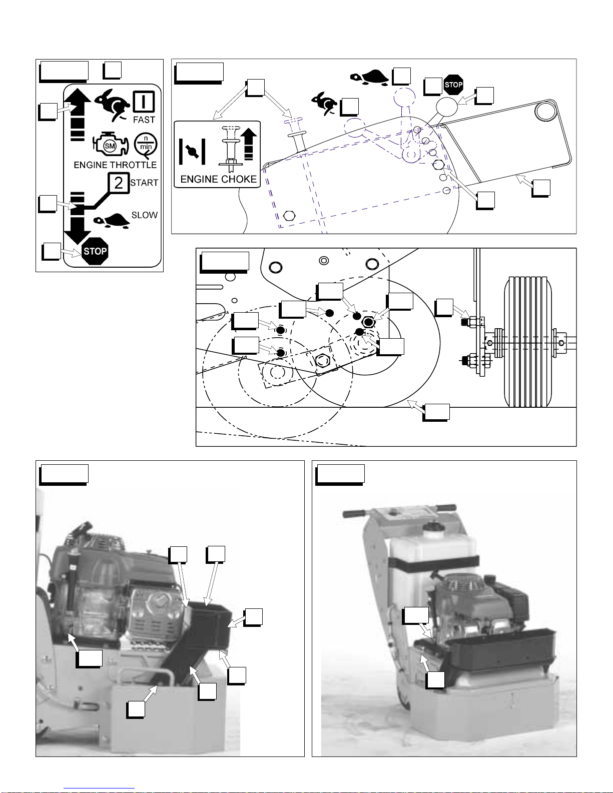
FIG. 11
F
E2
E1 F1
F2
F3
F4 G
L
FIG. 9
M
N
NN
O
N
M
L
C
NN
FIG. 10
D
FIG. 13
VV
WW
FIG. 12
EE DD
BB
CC
WW
AA
Z
Figures / Figuras
8
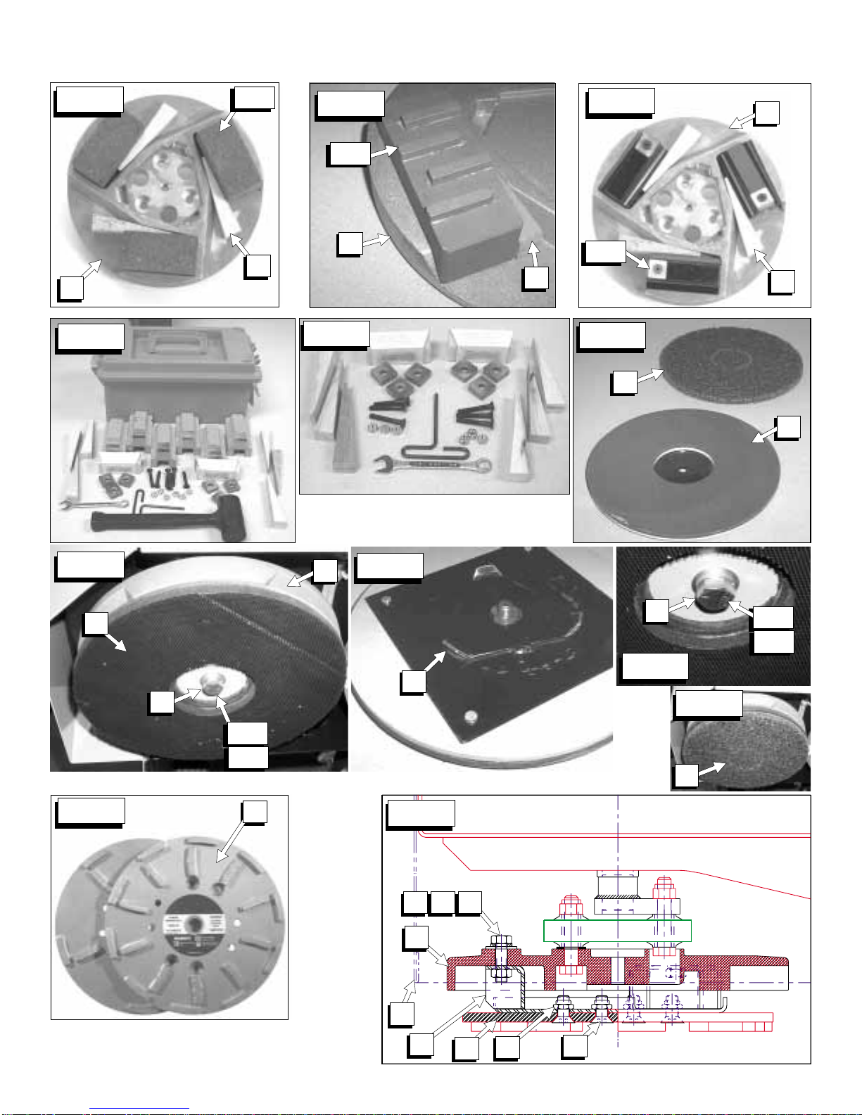
FIG. 16
P
U
GG 2
FIG. 17
GG 1
FIG. 14
U
P
P
U
GG 3
FIG. 15
FIG. 18
FIG. 24
Q
FIG. 25
P
QS1
FIG. 19
HH
JJ
FIG. 21
HH
T1T3 T2
A
RS2
Figures / Figuras
JJ
FIG. 23
FIG. 22
SS 1
SS 2
V1
FIG. 20
HH
SS 1
SS 2
V1
P
9
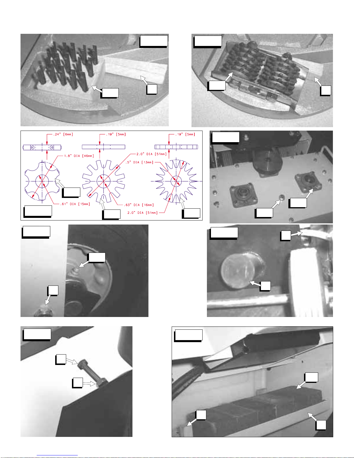
FIG. 29
RR 3
RR 1
FIG. 30
RR 2
G
FIG. 32
UU
YY
FIG. 28
GG5A
GG5C
GG5B
FIG. 26
GG 4 U
FIG. 27
U
GG 5
FIG. 31
XX
QQ
Figures / Figuras
FIG. 33
U
X
GG
10

11
Parts Identification:
A. Front Shield [FIG. 1].
B. Front Shield Bolts [FIG. 1, FIG. 3].
C. Adjustable Handle [FIG. 1].
D. Handle Bolts [FIG. 1].
E. Axle In Transport Position [FIG. 11].
F. Axle In Operation Position [FIG. 11].
G. Axle Stop Bolt [FIG. 11, FIG. 30].
H. Electrical ON / OFF Switch (Electric Model Only)
[FIG. 6].
I. ------
J. Voltage Change Switch (Electrical Model Only)
[FIG. 5].
K. Reset Button (Electrical Model Only) [FIG. 4].
L. Throttle Lever (Gasoline Model Only) [FIG. 10].
M. Engine STOP Position (Gasoline Model Only)
[FIG. 10].
N. Engine START Position (Gasoline Model Only)
[FIG. 10].
O. Engine Choke (Gasoline Model Only) [FIG. 10].
P. Accessory Disks [FIG. 20, FIG. 14, FIG. 15, FIG.
16].
Q. Multi-Segmented Diamond Disks [FIG. 24, FIG.
25].
R. Diamond Disk Adapter [FIG. 25].
S. Diamond Disk Attaching Hardware [FIG. 25].
S1. Flat Head Screws.
S2. Locknuts.
T. Diamond Disk Adapter Attaching Hardware [FIG.
25].
T1. Capscrew, 3/8-16UNC x 1-1/2”Long.
T2. Lockwasher 3/8”, Split Type.
T3. Washer, .3/8 SAE.
U. Wooden Wedges [FIG. 14, FIG. 15, FIG. 16].
V. Wrench, ½” (13 mm) x ¾” (19 mm) [FIG. 8]
V1. Wrench Can Be Used On Items Marked “V1”
[FIG 2, FIG. 3, FIG 20].
W. Lifting Eye (Electrical Model Only) [FIG. W].
X. Tool Storage Area: Holds 6 Extra 2 x 2 x 4”Tools
[GG], & 9 Extra Wooden Wedges [U]. [FIG. 33].
Y. Lifting Bail –Standard Equipment for Gas Model.
Z. Weight Tray (FIG. 12)
AA. Weight Tray Hardware –With Optional Weight Kit
[FIG. 12]
BB. Weight Box –With Optional Weight Kit [FIG. 12]
CC. Hold Down Bolts (Weight Box) [FIG. 12].
DD. Weight Bar [FIG. 12].
EE. Weight Bar Attaching Hardware [FIG. 12].
FF. Lifting Handles [FIG. 1].
GG. Tool (2 x 2 x 4”Type):
GG1. Grinding Block [FIG. 14].
GG2. Tungsten Carbide Segment Block [FIG. 16].
GG3. Diamond Blocks [FIG. 15].
GG4. Wire Brushes [FIG. 26].
GG5. Scarifier Wheels [FIG. 27].
GG5A. Star Wheel [FIG. 28].
GG5B. Beam Wheel [FIG. 28].
GG5C. Tungsten Carbide Wheel [FIG. 28].
HH. Tool Holding Pad [FIG. 19, FIG. 20, FIG. 21].
II. ------
JJ. Scrubbing Pad [FIG. 19].
KK. ------
LL. Electrical Plug [FIG. 1].
MM. Ground Fault Circuit Interrupter (GFCI) [FIG. 7].
NN. Engine “Fast”Speed (Gas Model Only) [FIG. 10].
OO. ------
PP. Gearbox Cover [FIG. 2].
QQ. Water Tank Kit [FIG. 2].
QQ1. Tank with Lid [FIG. 1].
QQ2. Water Tank [FIG. 1].
QQ3. Water Tank Bracket [FIG. 1].
QQ4. Hose Clamps [FIG. 1].
RR. Lubrication Points:
RR1. Spindle Bearings [Six (6) Places] [FIG. 29].
RR2. Rear Wheels [FIG. 30].
RR3. Gearbox Grease Port [FIG. 29].
SS. Tool Holding Pad Attaching Hardware [FIG. 20,
FIG. 22, FIG. 25].
SS1. Capscrew, Hex Hd, .500-20UNC x 1.25”.
SS2. Lockwasher, .500”, Split Type.
TT. Voltage Change Lock Bolt [FIG. 5].
UU. Belt Tensioning Drawbolt [FIG. 32].
VV. Serial Number Plate [FIG. 13].
WW.Oil Drain Hose [FIG. 12, FIG. 13].
XX. Dust Port Cap [FIG. 31].
YY. Belt Tensioning Jam Nut [FIG. 32].
ZZ. Motor Platform Capscrews [FIG. 3].
AAA. Hose Port Cover [FIG. 31].

12
SAFETY WARNINGS FOR OPERATION OF THIS MACHINE
DO read this entire operator’s manual before operating this machine. Understand all warnings, instructions, and controls.
DO keep all guards in place and in good condition.
DO wear safety-approved hearing, eye, head and respiratory protection.
DO read and understand all warnings and instructions on the machine.
DO read and understand the symbol definitions contained in this manual.
DO keep all parts of your body away from the grinding disks and all other moving parts.
DO know how to stop the machine quickly in case of emergency.
DO shut off the engine and allow it to cool before refueling.
DO inspect the accessory disk, and tool adapters for damage before installing the tools.
DO use only tools manufactured for use on surface grinders.
DO verify grinder drive configuration by checking engine / motor RPM, and spindle shaft RPM, pulley diameters.
DO read all safety materials and instructions that accompany any tool used with this machine.
DO inspect each tool carefully before using it. If there are any signs of damage or unusual wear, DO NOT USE THE
TOOL!
DO mount the tool solidly and firmly.
DO make sure the tool and accessory disk are clean and free of dirt and debris before mounting the tool on the saw.
DO use the correct tool for the type of work being done. Check with tool manufacturer if you do not know if tool is correct.
DO operate this machine only in well ventilated areas.
DO instruct bystanders on where to stand while the machine is in operation.
DO establish a training program for all operators of this machine.
DO clear the work area of unnecessary people. Never allow anyone to stand in near the machine while the engine is
running.
DO always tie down the machine when transporting.
DO use caution and follow instructions when setting up or transporting the machine.
DO have all service performed by competent service personnel
DO verify that the tool size is compatible with the machine before mounting the tool.
DO make sure the fuel caps of the machine and the fuel can are properly tightened before starting the engine. Move fuel
can at least 10 feet from machine after fueling.
DO clean the machine after each day’s use.
DO remove adjusting tool and wrenches from machine before turning it on.
DO keep the handles dry, clean and free of oil and dirt.
DO carefully maintain and clean for better and safer performance. Follow instructions for changing accessories. Inspect
tool cords periodically and, if damaged, have repaired by authorized service facility.
DO use caution when handling fuel.
DO always give a copy of this manual to the equipment user. If you need extra copies, call TOLL FREE 1-800-288-5040.
DO Determine the nature and volatility of any material that will come in contact with the grinding action of the tools used by
this machine.
DO operate the machine only in areas where the material in contact with the grinding tools is known.
DO use only non-flammable and proper substances to improve the material removal from the work area.

13
DO NOT operate this machine unless you have read and understood this operator’s manual.
DO NOT operate this machine without all guards in place.
DO NOT leave this machine unattended while the engine or motor is running.
DO NOT work on this machine while the engine or motor is running.
DO NOT operate this machine when you are tired or fatigued.
DO NOT operate the machine if you are uncertain of how to run the machine.
DO NOT use damaged equipment or tool.
DO NOT touch or try to stop a moving tool with your hand.
DO NOT transport a machine with the tools mounted on the machine.
DO NOT use a tool that has been dropped or damaged
DO NOT touch the tools immediately after use. These tools require several minutes to cool after operation.
DO NOT use damaged or worn accessory disk.
DO NOT allow other persons to be near the machine when starting, refueling, or when the machine is in operation.
DO NOT operate this machine in an enclosed area unless it is properly vented.
DO NOT operate this machine in the vicinity of anything that is flammable. Sparks could cause a fire or an explosion.
DO NOT operate this machine while under the influence of drugs or alcohol.
DO NOT operate this machine with any of the guards removed.
DO NOT operate this machine unless you are specifically trained to do so.
DO NOT start operation of the machine until you have a clear work area and secure footing.
DO NOT use flammable substances, unsecured loads or people as extra weight. Injury to the operator or other persons
could result!
DO NOT use flammable, or improper substances to improve the material removal from the work area.
DO NOT operate the machine if unknown substances are on or near the work area.
DO NOT operate the machine before you determine the nature and volatility of any material that will come in contact with
the grinding tools used by this machine.
*****************
This machine was designed for certain applications only. DO NOT modify this machine or use for any application
other than for which is it was designed. If you have any questions relative to its application, DO NOT use the
machine until you have written Diamant Boart, Inc. and we have advised you.
Diamant Boart Inc.
17400 West 119th Street
Olathe, Kansas 66061, USA

14
FELKER®Surface Trac SPECIFICATIONS
FEATURE MODEL
Model Number: ST15E ST11H
Item Number: 173366 173367
Power Source: Electric Gasoline
Maximum Horsepower: 1-1/2 (1,1 kw) 11 (8,2 kw)
Motor / Engine Rated RPM: 1725 3600
Brand: Baldor Honda
Model / Specification: TEFC GXV340
Voltage: 115 / 230 -----
Phase: Single -----
Full Load Current @ 115V: 19 -----
Full Load Current @ 230V: 9.5 -----
Displacement: ----- 20.6 cubic inches (338 cc)
Bore: ----- 3.2 inch (82 mm)
Stroke: ----- 2.5 inch (64 mm)
Cylinders: ----- 1
Fuel Capacity: ----- .61 US Gallon (2,3 Liter)
Oil Capacity: ----- 1.16 US Quart (2.32 US Pints) (1,09 Liter)
Air Filter: ----- Dual Element: Pleated Paper & Foam Pre Cleaner
Starter: Capacitor Recoil
Coolant: Air Air
Spindle Shaft RPM: 230 279 –560 (Variable Speed Using Engine Throttle)
Clutch Engagement RPM: N/A 1800
Nominal Weight: 309 Lb. (140 kg) 328 Lb. (149 kg)
Operating Weight
(With Tools, Fuel, Oil, Etc): 320-350 Lb.
(145-159 kg) 340-370 Lb.
(154-168 kg)
Grinding Width: 22.2 inches (56,4 cm)
Gearbox Ratio: 4.48 : 1
Handle: Six (6) Position Adjustment with Rubber Grips
Dust Port: 3.0”(76,2 mm) Outside Diameter will accept 3”(76mm) Inside Dia. Flex Hose
Tires & Wheels: 8”Diameter, ¾” Bore, Semi-Pneumatic,
Steel Wheel with Roller Bearings & Grease Fitting
Axle: ¾” Diameter, Zinc Plated with One Transport & Four (4) Operation Positions
Tool Storage Area (See FIG. 33):Holds Six (6) Extra Tools (2 x 2 x4”) and Nine (9) Extra Wooden Wedges
OPTIONS:
Water Tank Kit (P/N 177855): Plastic, 7.5 Gallon (28.4 Liter), Quick-Connect ON/OFF Valve, Brass Fittings &
Spray Nozzle, Weight 6.5 Lbs. (2,9 kg) Less Water
Weight Kit (P/N 177856): Includes Weight Tray, Removable Weight Box, & 58 Lbs. (26 kg) of Steel
Weights. Can Hold an additional Nine (9) Weight bars (Sold Separately)
[58 Lbs (26 kg)] for a Total Maximum Weight of 117 Lbs. (53 kg)
Lift Bail Kit (P/N 177901):
(For Gas/Electric Models) One Point Lifting, 7 Ga. x 1.5”(38 mm) Steel, Weight 14 Lbs. (6,3 kg)
Gas Model: Standard Equipment Beginning Spring 2000.
Electric Model: Has Lifting Eye (Standard Equipment), but this Kit Will Fit.
Diamond Disk Adapter Kit
(P/N 177861):
Attaches Two (2) 10”(254mm) Diameter Diamond Disks To the Machine. Kit
Includes adapter disks and all attaching hardware. Diamond Disks must be
purchased separately.

15
(DT15_dims.tif)
Dimensions (Note 1)
Item Length (cm) Description
A 50.2”(127.5) Length –Maximum (With Handle In Low Position)
B 25.12”(63.8) Width
C 37.6”(95.5) Operating Height (Maximum –Note 1)
D 37.0”(94.0) –31.5”(80.0) Handle Height (Maximum –Minimum)
E 24.2”(61.5) Handle Width
F 35.0”(88.9) Water Tank Height
G1.50”(3.8) Grind To Wall (Front and Side)
H 41.9 (106.5) Transport Height (Maximum –Note 2)
J 10.2”(25.8) Front Height
K 11.0”(27.9) Disk Diameter
L 22.2 (56.4) Grinding Width
M 11.200 (28.45) Spindle Center Distance
N9.6”(24.4) Width Inside Tires
O 14.6”(37.0) Width Outside Tires
Notes:
1. Dimensions are for the machine with the axle in “operation”position unless otherwise specified.
2. Dimension “H”is for the machine with the axle in “Transport”position.

16
Tool Application Guide
Tool Attachment To
Machine Task Surface Material
Grinding Stones
(See FIG. 14)
See Current
Product Catalog for
Part Numbers of
these Items.
Accessory Disk and
Wooden Wedges
(Section 4.1)
Light Grinding of Rough Areas
Available In Different Silicon Carbide “Grit”Sizes, such as:
TC-10 Coarse Grit: Maximum material removal, General grinding &
removal of trowel marks, high spots, and rough sections of concrete. Life
4-10 hours.
TC-24 Medium Grit: Lower material removal rate, Finer finish grinding of
concrete, and rough grinding of Terrazzo and other stone type. Life 6 –10
hours.
TC-80 Fine Grit: Still lower material removal rates. For polishing of
concrete and medium grinding on Terrazzo and stone type floors. Life 8 –
20 hours.
(The larger the number, the finer the grain structure, and the smoother the
surface material finish, and the longer the grinding stone life)
Concrete
Terrazzo
Other Stone Types
Diamond
Segment Blocks
(See FIG. 15)
See Current
Product Catalog for
Part Numbers of
these Items.
Accessory Disk and
Wooden Wedges
(Section 4.2)
Remove High Spots, Trowel & Rain Marks, Paints, Sealers & Mastics,
Uneven Joints, Aggressive Grinding of Large Rough Areas, Removal of
epoxies, paints and many thin film coatings, or Final Preparation for new
coating.
Available In Different “Grit”Sizes:
GB-10 General Purpose, GB-20 Abrasive Materials
GB-30 Epoxy & Non-Abrasive Materials.
Removal Rates: Up to five (5) times the material removal rate of Coarse
Grinding Stones.
Life: Up to 15 times the life of Grinding Stones.
Concrete
Terrazzo
Other Stone Types
Tungsten
Carbide Blocks
(FIG. 16, FIG. 17,
FIG. 18)
Accessory Disk and
Wooden Wedges
(Section 4.3)
Removal of Thick Paint Coatings, Not Recommended for Thin (< 5 mil)
Films of Materials. Not Recommended for adhesive, rubber deposits and
mastics which have a tendency to extrude or smear rather than “shear”
loose from the floor surface –however water or a water / sand mixture can
be added on the surface to reduce this problem.
Concrete, Epoxy,
Coatings, & Mastics
Scarifier Wheels
(FIG. 27, FIG. 28)
See Current
Product Catalog for
Part Numbers of
these Items.
Accessory Disk and
Wooden Wedges
(Section 4.4)
Remove Fiberglass, Ice, Oil-Dry, Foam-Fill Packing Material & Floor
Buildups. Lightly Texture Surface.
Star Wheel: Hardened Carbon Steel material. For removal of thin coatings
and encrusted accumulations of material. Cleaning concrete of asphalt
surfaces. Removing thick build-up of grease, paint, and some resins.
Light scarifying before application of coatings or sealer. Creates a swept,
or “broomed”type of finish.
Beam Wheel: Medium duty, for concrete and asphalt scarifying. De-
scaling steel decks. Removing thick material build-up of grease, paint, and
some resins. Twice the life, near the same cost as a star wheel.
Tungsten Carbide Wheel: Heavy Duty asphalt or concrete scarifying, or
de-scaling of steel decks. 10 times the life of a star wheel.
Concrete, and Tile
Wire Brushes
(FIG. 26)
Accessory Disk and
Wooden Wedges
(Section 4.5)
Light Scarifying & cleaning.
Notes: Should be rotated end for end in accessory disk every hour to avoid
the wire taking a set (flat wire will bend in one direction). External weight
added to machine will NOT normally increase production rates, but only
accelerate the wire brush wear rates.
Concrete, Asphalt,
Steel, and Tile
Diamond Disks
(FIG. 25)
See Current
Product Catalog for
Part Numbers of
these Items.
Adapter Plates
(Section 4.6)
Remove High Spots, Trowel & Rain Marks, Paints, Sealers & Mastics,
Uneven Joints, Aggressive Grinding of Large Rough Areas, Removal of
epoxies, paints and many thin film coatings, or Final Preparation for new
coating.
Available In Different “Grit”Sizes and 10 or 20 Diamond Segments (per
disk):
TDGH-10C for Cured Concrete (10 Segments)
TDGH-20C for Cured Concrete (20 Segments)
TDGH-20A for Asphalt or Abrasive Surfaces (20 Segments)
Removal Rates: Up to five (5) times the material removal rate of Grinding
Stones.
Life: Up to 15 times the life of Grinding Stones.
Concrete
Terrazzo
Other Stone Types
Scrubbing Pads
(FIG. 19) Tool Holder Pad
(Section 4.7)
Remove mildew, rust, or discoloration from concrete, clean concrete forms,
strip scale and rust from steel plate surfaces, remove fins or marks on
underlayment materials. Concrete, Steel

17
PRE-OPERATION CHECKLIST
Before leaving our factory, every machine is thoroughly tested. Follow our instructions strictly
and your machine will give you long service in normal operating conditions.
Before starting the machine, make sure that you read this entire Operations Manual and are
familiar with the operation of the machine.
WITH MACHINE COLD AND SETTING LEVEL:
Gasoline Models: Check engine oil. Fill to the full mark on dipstick with 10W30 oil, class MS, SD, SE or better.
Electric Models: Verify that all electrical connections are intact.
1-2 HOUR OPERATION CHECK LIST:
ALWAYS place the machine on a level surface with the engine / motor “OFF”, the ignition switch
set in the “OFF” position and disconnected from the power source before performing any
maintenance. Let the machine cool down!!
1. Check the engine air cleaner hose clamps. Tighten as required.
2. Tension the drive V-belts. DO NOT over tension!
SCHEDULED MAINTENANCE QUICK REFERENCE
Before performing any maintenance, ALWAYS place the machine on a level surface with the
engine / motor “OFF”, the ignition switch set in the “OFF” position and disconnected from the
power source!
SERVICE DAILY:
1. Check engine oil level.
2. Check all guards for damage.
3. Check hoses and clamps for damage or looseness. Tighten or replace as
necessary.
4. Check air cleaner. Clean or replace as required.
5. Clean the machine at the end of the day.
SERVICE EVERY 50 HOURS:
1. Replace engine oil and oil filter.
2. Clean engine air fins.
3. Check V-belt tension. DO NOT over tension!
4. Clean Engine fuel bowl.
18
•Mandatory
•Obligatorio •Prohibition
•Prohibición
•Indication
•Indicación•Warning Triangle
•Triángwulo De
Advertencia
These signs will give advice for your safety
Before leaving our factory every machine
is thoroughly tested.
Follow our instructions strictly and your machine
will give you long service in normal operating
conditions.
1. Features
Use: Surface grinding of concrete or other types of
flooring. For repairing horizontal surfaces that
have been damaged by the weather, or by
improper finishing methods, or that require
removal of deteriorated coatings, overlays, or
buildups.
Tools:
1) 2 x 2 x 4”(50 x 50 x 100 mm) size, Six (6) per unit.
In any of the types shown below:
a) Grinding Stones [FIG. 14]
b) Tungsten Carbide Segment Block [FIG.
16].
c) Tungsten Carbide Impregnated Grinding
Block (Not Shown)
d) Scarifier Blocks (Star, Beam, TC wheels)
[FIG. 27 & FIG. 28].
e) Wire Brushes [FIG. 26].
f) Diamond Blocks [FIG. 15].
2) Multi-Segmented Diamond Disks: Two (2) disks per
unit, 10”(250 mm) diameter, 10 or 20 diamond
segments on each disk [FIG. 24 & FIG. 25].
3) Tool Holding Pad, with “hook-and-loop”type of tool
attachment, holds the following [FIG. 19]:
a) Scrubbing Pad [JJ] [FIG. 19]: Two (2) pads
per unit, 10”(250 mm) diameter, Nylon
mesh Impregnated with Silicon Carbide.
(For information contact your Dealer)
Depth of Cut (Maximum):
See Section 4 (Tool Installation & Application)
Maximum material Size: N/A
Nominal & Operating Weight: See “Specifications”.
Dimensions, Grinding Width, Spindle Shaft RPM:
See “Saw Dimensions”.
Before starting up machine make sure you
read these instructions and are familiar
with the operation of this machine.
The working area must be completely clear,
well lit and all safety hazards removed (no
water or dangerous objects in the vicinity)
The operator must wear
protective clothing
appropriate to the work he
is doing.
We recommend hearing,
respiratory and eye
protection.
Any persons not involved in the work,
should leave the area.
Only work of flat horizontal areas.
Working on steep slopes or hills could
cause the operator to lose control of the
machine. This could result in injury or
death to the operator or other persons in
or near the work area!
2. Assembly
q
When unpacked, this unit is fully assembled,
except for installation of the grinding “tools”. For
tool installation See Section 4 of this document.
q
The dealer or end user must do the installation of
optional or accessory items, such as a water tank
kit.
3. Check Before Operating
All Models:
q
Take into account the working conditions from a
health and safety point of view.
q
For start up refer to the engine, or motor manual.
19
Electric Models:
The applicable national and local electrical
codes and enforcement bodies will be the
determining authority on the proper
connections and use of this machine. In all
cases it the operator/owner’s responsibility to
ensure that this equipment is in full
compliance with these codes.
All machine adjustments & maintenance shall
only be done after the machine’s power switch
has been put in the “OFF”position & the
power supply cord completely disconnected.
q
Make sure that the extension cord length is
properly sized for the motor used on this saw. See
the chart in Section 2 of this document.
q
Single phase 1-1/2 hp motors are factory wired for
115 volt service and furnished with the correct
NEMA configuration Plug (LL) [See FIG. 1] on the
motor pigtail. See Table 1 below for the proper
matching connectors:
Table 1
Electric Motor Plugs & Connectors
Motor Wired For
Voltage
Motor Pigtail
Plug
(NEMA No.)
Connector
Required
(NEMA No.)
1-1/2 HP 115 V L5-20P L5-20R
1-1/2 HP 230 V L6-15P L6-15R
q
For operator convenience, the 1-1/2 hp motor has
a Voltage Change Switch (J) [See FIG. 5] that
allows operation on a 115 VAC or a 230 VAC
power source. The voltage change switch (J) is
mounted on the terminal box of the motor and must
be set to either 115, or 230 Volt, to match the
voltage supply. Make sure that the Voltage Change
Lock Bolt (TT) is in position. It will prevent the
Voltage Change Switch [See FIG. 5] from being
accidentally moved into the wrong position.
WARNING: The Voltage Change Switch (J)
position is never to be changed while the motor
is running. Make sure that the Voltage Change
Lock Bolt (TT) is in position. It will prevent the
Voltage Change Switch from being accidentally
moved into the wrong position.
q
Local electrical codes may require changing the
plug on the motor to the proper NEMA connector to
match the voltage supply.
q
The operator must use plug and receptacle
connectors on all power cords (machine and
extension), designed and approved for the selected
motor voltage and equal to or greater than the
rated motor full load current.
q
The service receptacle, branch circuit conductors,
and overcurrent protection shall have an ampere
rating equal to or greater than the motor full load
current. According to the National Electrical Code
if the branch circuit has two or more receptacles,
each receptacle has a maximum load ampere
rating equal to 80% of the receptacle’s rating.
When this machine is set up to operate on 115
VAC, the motor has a full load rating of 19
amperes. This means that when operating this
machine on 115VAC, it can only be used on a
branch circuit with ONE 20-ampere rated
receptacle. If the circuit has two or more 20-
ampere receptacles, they each have load rating of
16 amperes and cannot be used by this machine.
WARNING: Always make sure the unit in
connected to a properly grounded electrical
outlet. Failure to comply with this warning
could result in serious bodily injury or death!
WARNING: DO NOT operate on low voltage!
Low voltage causes loss of power, motor
overheating, and possibly motor winding
burnout. Voltage should be checked at the
motor while it is operating.
q
The extension cord(s) used must have a voltage
rating greater than the selected voltage (115 or
230) and be sized for the rated motor full load
amps (as marked on motor specification plate).
q
Good motor performance depends on proper
voltage. Extension cords that are too long and / or
too small reduce the voltage to a motor under load.
Operating below this minimum voltage will cause
an increase in motor current resulting in slow
startup, and overheating in the motor and controls.
Sustained operation under these conditions will
result in permanent damage to the motor and
controls.
q
Long extension cords will probably have to be
oversized to minimize the voltage drop to the
machine. The size of the extension cord is
dependent on the total conductor length (all
extension cords) & the quality of the power source.
The power cord size shall be capable of supplying
a minimum of 90% of the motor nameplate
voltage at the motor, when the motor is running
rated full load.
q
Make sure that the extension cord length is
properly sized for the motor used on this machine.
Use extension cords NO SMALLER than the sizes
indicated in Table 2 below:
Table 2
EXTENSION CORD SIZE (Minimum)
MOTOR 50 ft Long 75 ft Long 100 ft Long
HP 120 V 230 V 120 V 230 V 120 V 230 V
1-1/2 # 12 # 14 # 10 # 14 # 8 # 14
q
The branch circuit must have overcurrent
protection in the form of a circuit breaker or fuses.
The purpose of the overcurrent protection is to limit
the current in the branch circuit conductors and
connections to an amount equal to or less than
their ratings. This is to prevent overheating that
can lead to damage or a fire. The overcurrent

20
protection will not protect the operator from an
electrical shock due to improper grounding
practice, frayed or cracked extension cords, or
other defective electrical components. This
exposure to electrical shock increases greatly
whenever the equipment is used around water or
other conductive fluids. The operator will be
provided with electrical shock protection whenever
the machine is connected to a circuit that has a
Ground Fault Circuit Breaker. The Ground Fault
Circuit Breaker will open the circuit whenever it
senses a fault current, greater than a few
milliamps, in the ground path. If a receptacle with a
Ground Fault Circuit Breaker is not available, a
Portable Ground Fault Circuit Interrupter [MM] [See
FIG. 7] can be used at the branch receptacle to
provide the same level of protection.
Gasoline Model:
q
Engine Fuel: Check the engine operation manual.
Unleaded gasoline is recommended.
q
Engine Oil: Put the AXLE in the OPERATION
POSITION [F] [See FIG. 11] so that the engine is in
a horizontal position, then, check that the engine oil
level is correct. Check the oil level frequently to
ensure that the level never falls below that
specified in the engine operation manual. If the oil
level is low, add SAE 10W30, service classification
SF or SG oil (for normal conditions) as
recommended in the engine operation manual. DO
NOT overfill engine with oil!
q
Before starting the engine verify that the Throttle
Lever [L] is between the START [N] and STOP [M]
position. This will allow the engine to be started
while the clutch is disengaged. NOTE: The engine
clutch will engage at 1800 RPM, and the Accessory
Disks [P] will begin to rotate.
q
Before starting the engine, verify that the engine
does NOT exceed 20 degrees angle of inclination
when the unit is in operation.
WARNING: Run the machine only if the
grinding heads are on the ground. Raising the
front of the machine with the engine or motor
running could cause injury or death to by-
standers or the operator. Also, engine
inclination angles greater than 20 degrees
could cause severe engine damage and void
your engine warranty!
4. Tool Installation
TOOL INSTALLATION:
1) Rear Axle Position (See FIG. 11): Make sure the
Axle is in the Transport Position [E]. Using TABLE
3 (below) install the Axle Stop Bolts [G] in the
proper position for the tool being mounted. The
Axle Stop Bolts [G] are factory installed in the F2
position.
Table 3 shows the tools specified by our
company. Tools from other manufactures
may fit onto this machine. Measure “Tool
Height”to determine the proper axle position
(See TABLE 4) for these tools.
TABLE 3
Rear Axle Positions (See FIG. 11)
Tool Tool Height Axle Position
Grinding Stones 2.0”(51 mm) F2
Tungsten Carbide
Block 2.1”(53 mm) F2
Diamond Segment
Block 2.1”(53 mm) F2
Star wheels 2.25”(57 mm) F2
Beam Cutter Wheels 2.25”(57 mm) F2
TC Wheels 2.15”(54 mm) F2
Diamond Disks 2”(51 mm) F2 or E2
Scrubbing Pad
(with Adapter) 1.7”
(43.2mm) F3
If the tool to be installed is not listed in TABLE 3:
a) Measure the “Tool Height”.
TABLE 4
Tool Height for Axle Positions (See FIG. 1)
Axle Position Minimum Tool Height
F1 2.44”(62 mm)
F2 2.00”(50.8 mm)
F3 1.69”(42.9 mm)
F4 1.00”(25.4 mm)
b) Using TABLE 4, find a “Minimum Tool Height”
equal to, or greater than, the measured tool height.
c) Referencing FIG. 11, install and tighten the Axle
Stop Bolts [G] in the Axle Position (F1, F2, etc)
determined from step b) above.
2) Raise Front Shield (A): Loosen the three (3)
Capscrews [B] that hold the Front Shield [A] in
position. Raise the Front Shield to its upper
position, then tighten the Capscrews [B] to hold it in
place.
3) Tilt Machine Backwards: When on a flat surface,
tilt the machine backward until the Handles [FF]
rest on the ground. If you are not sure the machine
will stay in this position, add a weight or other
device to the handle to secure them to the ground.
WARNING: Make sure the machine is stable
when the front end is raised into the air!
Secure the machine in this position if you are
not sure about its stability. Secure machine
BEFORE starting attachment of the tools to
the accessory disks!
4) Tool Installation on Accessory Disk [P]:
See FIG. 14, FIG. 15, FIG. 16, FIG. 26, FIG. 27
a) Place the Tool [GG 1] so that it rests against the
back and outside of the tool holding area of the
This manual suits for next models
1
Table of contents
Popular Grinder manuals by other brands

Makita
Makita 9527PB Parts Breakdown

Universal Tool
Universal Tool UT8754 Operator instructions

Haybuster
Haybuster H-1135 operating instructions

King Tools & Equipment
King Tools & Equipment 1080-0 Operators instructions & parts list

Hitachi
Hitachi G 12STA Handling instructions

Hitachi
Hitachi G 10SD2 Handling instructions

GRAPHITE PRO
GRAPHITE PRO 59GP002 manual

MaxPro PROFESSIONAL
MaxPro PROFESSIONAL MPAG680/100 manual

Dexter Power
Dexter Power AG230-4.1 user manual

Bunn
Bunn G Series Installation & operating guide

EINHELL
EINHELL 44.305.83 Original operating instructions

Black & Decker
Black & Decker BDEG400 instruction manual


