Archmeter PS1000 User manual

PS1000 Evaluation Board
User Guide
V1.0
Preliminary datasheet
Arch Meter Corporation
4F, No.3-2, Industry E. Rd. 9, Science -Based Industrial Park,
Hsinchu, Taiwan 310, R.O.C.
Tel: 886-3-563-1359 Fax: 886-3-5631663
E-mail : sales@archmeter.com.tw http://www.archmeter.com

Arch Meter Corporation PS1000 Evaluation Board User Guide V1.0
PS1000Rev. 1.1 Mar.2006 1/ 22 www.archmeter.com
Index

Arch Meter Corporation PS1000 Evaluation Board User Guide V1.0
PS1000Rev. 1.1 Mar.2006 2/ 22 www.archmeter.com
1. PS1000 EVB Hardware
This evaluation board is designed for PS1000 test. Users could download MCU
program and watch debug message through USB interface. Users also could use LCD
to display messages. There are three sets of ADC inputs (Va, Ia, and Ib) in this EVB.
V1
I1
I2
Voltage
Sensor
Current
Sensor
PS1000
LCD
Key Pad
Battery
FRAM
Comm *3
I2C
Battery
control
Circuit
Flash Memory
kWh Pulse
Output
RTC Power
I/O
I/O
Power
2.5V3.3V
5V
I/O
I/O
Main Power
I/O
Push bottom
UART
SPI
Fig : Block Diagram
Fig : EVB board

Arch Meter Corporation PS1000 Evaluation Board User Guide V1.0
PS1000Rev. 1.1 Mar.2006 3/ 22 www.archmeter.com
Fig : EVB board with LCD
zPower
-Users could use 5V power supply by connecting 5V Power Connector or
USB power (5V) by switching USB Power Source.
-The EVB can powered by external 5V power supply or from USB. When this
EVB would like to powered by USB interface. Please turn-on one of USB
power source switch which USB port already connected to computer.
zProgram Download / Debug Message
-Users could use USB interface to download program and watch debug
message.
zMCU Mode Switch
-Users could change MCU operation mode by controling this switch.
-The configuration list is shown in the table below. (ON: 0, OFF:1)
-
OFF:1 S2 ON:0

Arch Meter Corporation PS1000 Evaluation Board User Guide V1.0
PS1000Rev. 1.1 Mar.2006 4/ 22 www.archmeter.com
Switch
[4321] MCU ROM RAM Notes
0001 Internal Shadow RAM (Power On) XDATA+ I/O Memory Normal Operation 1 (1)
0011 Internal Internal 2K ROM Shadow RAM + I/O Memory Download Mode (2)
0111 Internal Shadow RAM XDATA+ I/O Memory Normal Operation 2 (3)
(1) After CPU reset, program will be duplicated from flash to the shadow RAM, and starting the exe file on the shadow RAM.
(2) Upon running download program, select download program to SPI flash or to shadow.
(3) After reset CPU, the exe. File will be executed on the shadow RAM mode. If electricity been removed, then the shadow
RAM data will be cleared. If under running download, please select the download program to shodow.
zFor the external interface definition, please check the below description.
1. SSP I/F (JP9) Pin definition
1: CLK
2: FSX
3: DX
4: FSR
5: DR
6: GND
2. Debug Pin (J10) Definition
Users could debug easier by probing these debug pins in J10.
1 SPI_CS (Internal SPI Flash) 2 X
3 SPI_CS (External SPI Flash) 4 X
5 SPI_SCK 6 X
7 SPI_SI 8 X
9 SPI_SO 10 X
11: I2C_SCL 12 X
13 I2C_SDA 14 X
15 UART1_RXD 16 X
17 UART1_TXD 18 X
19 UART0_RXD 20 X
21 UART0_TXD 22 X
3. ADC Connector Definition
Follow the step below to measure voltage:
1) Connect input voltage to pin 1 (VAP) and input ground to pin 3 (VAM)
in JP1.

Arch Meter Corporation PS1000 Evaluation Board User Guide V1.0
PS1000Rev. 1.1 Mar.2006 5/ 22 www.archmeter.com
2) Connect pin 2 with pin 1 (GND) or pin 3 (VCM2) in JP2 based on users
requirement.
Va I/F (JP1) Pin definition
1: Voltate Input (VAP)
2: NC
3: VAM
Va Reference I/F (JP2) Pin definition
1: GND
2: VAM
3: VCM2 (VDD33/2)
Follow the step below to measure current:
1) Connect differential input current to pin 1 (IAP) and pin 2 (IAN) or pin
3 (IBP) and pin 4 (IBN) in JP3.
2) Connect pin 2 with pin 1 (VCM1) and connect pin 3 with pin 4(GND) in
J1 or J2 based on users requirement.
Ia/Ib I/F (JP3) Pin definition
1: Differential Current Input (IAP)
2: Differential Current Input (IAN)
3: Differential Current Input (IBP)
4: Differential Current Input (IBN)
Ia Reference I/F (J1) Pin definition
1: VCM1 (VDD33/2)
2: IA Reference
3: Jump to Pin4
4: GND
Ib Reference I/F (J2) Pin definition
1: VCM1 (VDD33/2)
2: IB Reference
3: Jump to Pin4
4: GND

Arch Meter Corporation PS1000 Evaluation Board User Guide V1.0
PS1000Rev. 1.1 Mar.2006 6/ 22 www.archmeter.com
2. PS1000 EVB Firmware
Main Program
Provides memory_mapping.h , Basic.h , Basic.obj for users’ application ;
among then , memory_mapping.h defines PS1000 internal register and I/O ,
Basic.h defines Basic.obj subroutine and Parameters , Basic.obj also include DSP
initialization , Timer0 initialization , UART0 initialization , Timer0 interrupt
subroutine , UART0 interrupt subroutine , Modbus communication subroutine ,
and calculation subroutine for measuring parameters .
Start
Initial DSP
Initial Timer0
Initial UART0
Initial 8051
EA=1
CALL
Modbus_Sub
DSPStatus.7=1
CALL
Calc_Sub
CALL
Self_Sub2
CALL
Self_Sub1
Y
N

Arch Meter Corporation PS1000 Evaluation Board User Guide V1.0
PS1000Rev. 1.1 Mar.2006 7/ 22 www.archmeter.com
Basic.obj include
Sub name Description
Init_DSP Download DSP ROM code , initial DSP register
Init_Timer0 initial Timer0 register
Init_UART0 initial UART register (Baud Rate , Stop bit …etc)
Init_8051 initial 8051 register , parameter
Modbus_Sub Communication(Modure) Procedure
Calc_Sub Calcuation V , I , Watt , VA ,Var , PF …….
kWh Pulse Output Procedure
Calibration Procedure
Measurement
Voltage ∑
=
=N
kakAArms vVGV
0
2
*
Current ∑
=
=N
kakAArms iIGI
0
2
*
Watt
∑
=
=N
kakakAAA ivIGVGP
0
)*(**
VA ArmsArmsA IVS *=
Var AAA PSQ −=
Power Factor
A
A
AS
P
pf =
Phase Angle )(cos 1AArmsArms pfIV −
=∠
Watt Sum BAtotal PPP +=
Var Sum BAtotal QQQ +=
VA S u m 22 totaltotaltotal QPS +=

Arch Meter Corporation PS1000 Evaluation Board User Guide V1.0
PS1000Rev. 1.1 Mar.2006 8/ 22 www.archmeter.com
kWh Pulse Output
kWh Pulse Output time calculated by Timer0 , and pulse outputted at p1.0
Calculation for kWh pulse output time
Let meter constant as Kh (wh/pulse) ,
Current usage as a watt
then time interval of two pulse outputs will be
a
Kh
t6060 ××
=sec
Ex : meter constant is 20 wh/pulse , Current conditions are 110V , 5A , PF=0.8
the time interval between two pulse can be found as
6363.163
8.05110
606020 =
×× ××
=tsec
Communication
Potocol : Modbus
Transmission Modes : RTU mode
The format for each byte in RTU mode is:
Coding System: 8–bit binary, hexadecimal 0–9, A–F
Two hexadecimal characters contained in each
8–bit field of the message
Bits per Byte: 1 start bit
8 data bits, least significant bit sent first
2 stop bits
Error Check Field: Cyclical Redundancy Check (CRC)
Function Codes
The function code part of a Modbus message defines the action to be taken by the
slave.
The Integral products support the following function codes:
Code MODBUS_ name Description
03 Read Holding Registers Read the contents of read/write location
04 Read Input Registers Read the contents of read only location
16 Pre-set Multiple Registers Set the contents of read/write location

Arch Meter Corporation PS1000 Evaluation Board User Guide V1.0
PS1000Rev. 1.1 Mar.2006 9/ 22 www.archmeter.com
Holding Register:
Modbus start
address (HEX) Parameter Format FRAM address
0000h Calibration Step Unsigned int 0800h
0001h Calibration Time Unsigned int 0802h
0002h 0804h
0003h
Reference Voltage #1 IEEE 754
Floating Point 0806h
0004h 0808h
0005h
Reference Current #1 IEEE 754
Floating Point 080ah
0006h 080ch
0007h
Reference Phase Angle #1 IEEE 754
Floating Point 080eh
0008h 0810h
0009h
Reference Voltage #2 IEEE 754
Floating Point 0812h
000ah 0814h
000bh
Reference Current #2 IEEE 754
Floating Point 0816h
000ch 0818h
000dh
Reference Phase Angle #2 IEEE 754
Floating Point 081ah
000eh 081ch
000fh
Reference Voltage #3 IEEE 754
Floating Point 081eh
0010h 0820h
0011h
Reference Current #3 IEEE 754
Floating Point 0822h
0012h 0824h
0013h
Reference Phase Angle #3 IEEE 754
Floating Point 0826h
0014h 0828h
0015h
Reference Voltage #4 IEEE 754
Floating Point 082ah
0016h 082ch
0017h
Reference Current #4 IEEE 754
Floating Point 082eh
0018h 0830h
0019h
Reference Phase Angle #4 IEEE 754
Floating Point 0832h
001ah 0834h
001bh
Reference Voltage #5 IEEE 754
Floating Point 0836h
001ch 0838h
001dh
Reference Current #5 IEEE 754
Floating Point 083ah
001eh 083ch
001fh
Reference Phase Angle #5 IEEE 754
Floating Point 083eh
0020h 0840h
0021h
Reference Voltage #6 IEEE 754
Floating Point 0842h
0022h Reference Current #6 IEEE 754 0844h

Arch Meter Corporation PS1000 Evaluation Board User Guide V1.0
PS1000Rev. 1.1 Mar.2006 10/ 22 www.archmeter.com
Modbus start
address (HEX) Parameter Format FRAM address
0023h Floating Point 0846h
0024h 0848h
0025h
Reference Phase Angle #6 IEEE 754
Floating Point 084ah
0026h 084ch
0027h
Reference Voltage #7 IEEE 754
Floating Point 084eh
0028h 0850h
0029h
Reference Current #7 IEEE 754
Floating Point 0852h
002ah 0854h
002bh
Reference Phase Angle #7 IEEE 754
Floating Point 0856h
002ch 0858h
002dh
Reference Voltage #8 IEEE 754
Floating Point 085ah
002eh 085ch
002fh
Reference Current #8 IEEE 754
Floating Point 085eh
0030h 0860h
0031h
Reference Phase Angle #8 IEEE 754
Floating Point 0862h
0032h Modbus Address Unsigned int 0864h
0033h Baud Rate 0:9600 , 1:19200 0866h
0034h Kh value 30 – 4320
(0.3 – 43.2 Wh) 0868h
0035h Year 00-99 086ah
0036h Month 1-12 086ch
0037h Date 1-31 086eh
0038h Hour 0-23 0870h
0039h Minute 0-59 0872h
003ah Second 0-59 0874h
003bh Day of Week 0(Sun) – 6(Saturday) 0876h
Input Register:
Modbus start
address (HEX) Parameter Format FRAM address
0000h 0c00h
0001h
Voltage 1 IEEE 754
Floating Point 0c02h
0002h 0c04h
0003h
Current 1 IEEE 754
Floating Point 0c06h
0004h Current 2 IEEE 754 0c08h

Arch Meter Corporation PS1000 Evaluation Board User Guide V1.0
PS1000Rev. 1.1 Mar.2006 11/ 22 www.archmeter.com
Modbus start
address (HEX) Parameter Format FRAM address
0005h Floating Point 0c0ah
0006h 0c0ch
0007h
Watt 1 IEEE 754
Floating Point 0c0eh
0008h 0c10h
0009h
Watt 2 IEEE 754
Floating Point 0c12h
000ah 0c14h
000bh
VA 1 IEEE 754
Floating Point 0c16h
000ch 0c18h
000dh
VA 2 IEEE 754
Floating Point 0c1ah
000eh 0c1ch
000fh
Var 1 IEEE 754
Floating Point 0c1eh
0010h 0c20h
0011h
Var 2 IEEE 754
Floating Point 0c22h
0012h 0c24h
0013h
Power Factor 1 IEEE 754
Floating Point 0c26h
0014h 0c28h
0015h
Power Factor 2 IEEE 754
Floating Point 0c2ah
0016h 0c2ch
0017h
Phase Angle 1 IEEE 754
Floating Point 0c2eh
0018h 0c30h
0019h
Phase Angle 2 IEEE 754
Floating Point 0c32h
001ah 0c34h
001bh
Watt Sum IEEE 754
Floating Point 0c36h
001ch 0c38h
001dh
VA Sum IEEE 754
Floating Point 0c3ah
001eh 0c3ch
001fh
Var Sum IEEE 754
Floating Point 0c3eh
0020h 0c40h
0021h
Wh IEEE 754
Floating Point 0c42h
0022h 0c44h
0023h
VAh IEEE 754
Floating Point 0c46h
0024h 0c48h
0025h
Varh IEEE 754
Floating Point 0c4ah

Arch Meter Corporation PS1000 Evaluation Board User Guide V1.0
PS1000Rev. 1.1 Mar.2006 12/ 22 www.archmeter.com
IEEE 754 Format
The bits in an IEEE 754 format have the following significance:
Data Hi Word,
Hi Byte
Data Hi Word,
Lo Byte
Data Lo Word,
Hi Byte
Data Lo Word,
Lo Byte
SEEE EEEE EMMM MMMM MMMM MMMM MMMM MMMM
Where:
S represents the sign bit where 1 is negative and 0 is positive
E is the two’s complement exponent with an offset of 127 i.e. an exponent of zero
is represented by 127, an exponent of 1 by 128 etc.
M is the 23-bit normal mantissa. The highest bit is always 1 and, therefore, is not
stored.
For each floating point value requested two MODBUS_ registers or points (four
bytes) must be requested. The received order and significance of these four bytes for
the Integral products is shown below:
Data Lo Word,
Hi Byte
Data Lo Word,
Lo Byte
Data Hi Word,
Hi Byte
Data Hi Word,
Lo Byte
Calibration
1. filling measuring time required for calibration
2. determining external voltage and current sources
3. after reaching steady , filling calibration step to Modbus Holding Register 0000h
4. when Modbus Holding Register 0000h = 0 being detected , filling the external
voltage and current reference values to respective Modbus Holding Registers
5. repeating 2-4 for 8 times
6. filling Modbus Holding Register 0000h = 9 , Calibration parameters will be
calculated by PS1000
Calibration Step
1 Calibration Pointer #1 for Current Gain x8
2 Calibration Pointer #2 for Current Gain x8
3 Calibration Pointer #3 for Current Gain x4
4 Calibration Pointer #4 for Current Gain x4
5 Calibration Pointer #5 for Current Gain x2
6 Calibration Pointer #6 for Current Gain x2
7 Calibration Pointer #7 for Current Gain x1
Arch Meter Corporation PS1000 Evaluation Board User Guide V1.0
PS1000Rev. 1.1 Mar.2006 13/ 22 www.archmeter.com
8 Calibration Pointer #8 for Current Gain x1
9 Calculate Calibration Parameter
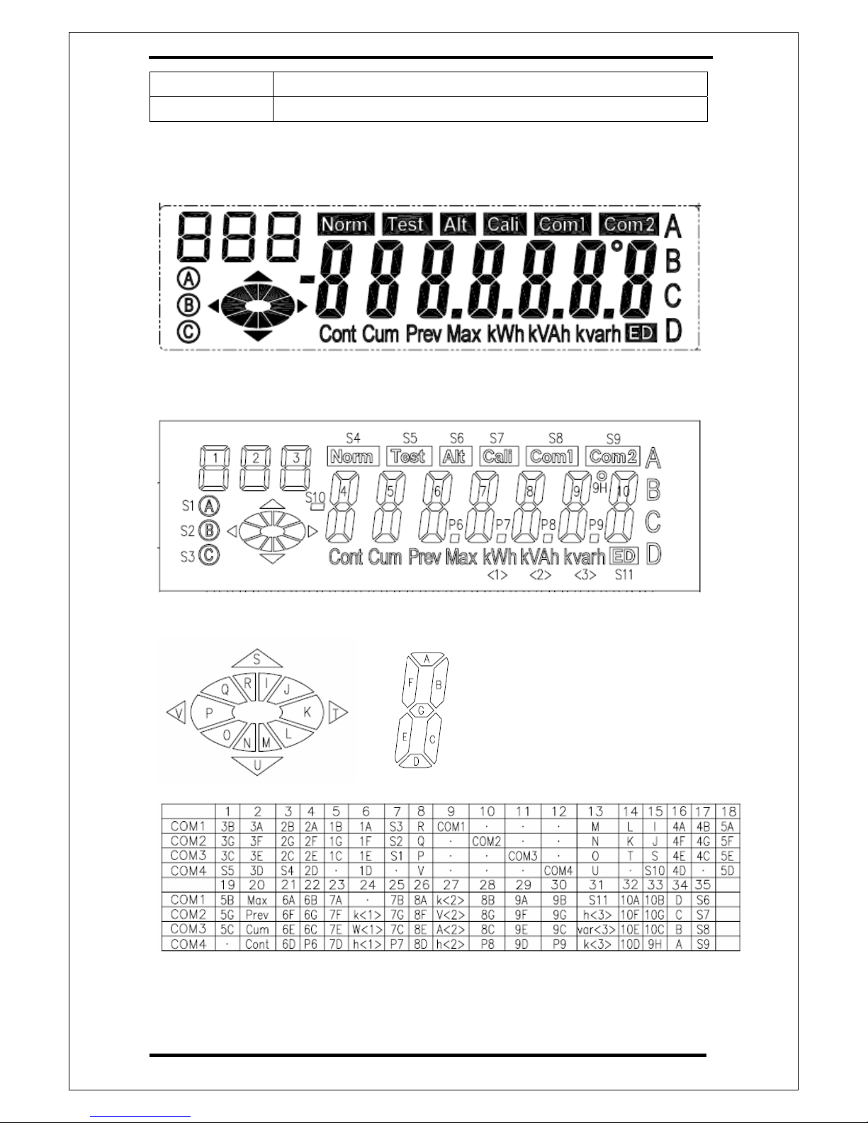
Display

Arch Meter Corporation PS1000 Evaluation Board User Guide V1.0
PS1000Rev. 1.1 Mar.2006 14/ 22 www.archmeter.com
3.PS1000 Download Program
Download Program
For PL0311 application, users need this application program to download MCU
program. The graphic interface is shown in the diagram below.
zRS232 Port Selection
-The selection of RS232 port for user uses to download program.
-The selection could be set from COM1 to COM6.
zRS232 BaudRate
-The baudrate of RS232 communication with PC.
-The baudrate is fixed to 19200 in PL0311 IROM.
-For feature use, the baudrate in this AP could be set to 4800, 9600, 19200,
38400, 57600(For PS1000),115200
zDownload Program to
-Memory in which user wants the program downloaded.
-The memory could be set to SHADOW or SPI FLASH.
zFlash Type
-Flash type that user wants to use.
-The flash type could be set to ATMEL, PMC, MXIC(For PS1000), and SST.

Arch Meter Corporation PS1000 Evaluation Board User Guide V1.0
PS1000Rev. 1.1 Mar.2006 15/ 22 www.archmeter.com
zFilename
-The name of file to load.
zProgress Bar
-The progress of download.
zMessage Window
- The message of download.
Operation Procedure
When start using this AP, please make sure the COM port connection first and
follow the correct procedure.
1. Choice the correct COM port and baud rate
2. Select the download Location (Shadow or SPI Flash)
3. If choice the SPI Flash, please choice the flash type (MXIC, PMC, ATMEL
or SST)
4. Select the download program
5. Press the download button and start download the program
6. Check the message box output. If down fail please re-try again.
Trouble Shooting
1. If EVB loss power during the download operation, it may cause the program
hang-up. So, please terminate the program and re-start again.
During CPU reset, the debug port of PS1000 will printout a string to show you it is in
the status of current download mode.

Arch Meter Corporation PS1000 Evaluation Board User Guide V1.0
PS1000Rev. 1.1 Mar.2006 16/ 22 www.archmeter.com
APPENDIX

Arch Meter Corporation PS1000 Evaluation Board User Guide V1.0
PS1000Rev. 1.1 Mar.2006 17/ 22 www.archmeter.com

Arch Meter Corporation PS1000 Evaluation Board User Guide V1.0
PS1000Rev. 1.1 Mar.2006 18/ 22 www.archmeter.com

Arch Meter Corporation PS1000 Evaluation Board User Guide V1.0
PS1000Rev. 1.1 Mar.2006 19/ 22 www.archmeter.com
Table of contents


