Quectel L89 EVB User manual

L89 EVB User Guide
GNSS Module Series
Rev. L89_EVB_User_Guide_V1.0
Date: 2019-12-10
Status: Released
www.quectel.com

GNSS Module Series
L89 EVB User Guide
L89_EVB_User_Guide 1 / 26
Our aim is to provide customers with timely and comprehensive service. For any
assistance, please contact our company headquarters:
Quectel Wireless Solutions Co., Ltd.
Building 5, Shanghai Business Park Phase III (Area B), No.1016 Tianlin Road, Minhang District, Shanghai,
China 200233
Tel: +86 21 5108 6236
Email: info@quectel.com
Or our local office. For more information, please visit:
http://www.quectel.com/support/sales.htm
For technical support, or to report documentation errors, please visit:
http://www.quectel.com/support/technical.htm
Or email to: support@quectel.com
GENERAL NOTES
QUECTEL OFFERS THE INFORMATION AS A SERVICE TO ITS CUSTOMERS. THE INFORMATION
PROVIDED IS BASED UPON CUSTOMERS’ REQUIREMENTS. QUECTEL MAKES EVERY EFFORT
TO ENSURE THE QUALITY OF THE INFORMATION IT MAKES AVAILABLE. QUECTEL DOES NOT
MAKE ANYWARRANTY AS TO THE INFORMATION CONTAINED HEREIN, AND DOES NOT ACCEPT
ANY LIABILITY FOR ANY INJURY, LOSS OR DAMAGE OF ANY KIND INCURRED BY USE OF OR
RELIANCE UPON THE INFORMATION. ALL INFORMATION SUPPLIED HEREIN IS SUBJECT TO
CHANGE WITHOUT PRIOR NOTICE.
COPYRIGHT
THE INFORMATION CONTAINED HERE IS PROPRIETARY TECHNICAL INFORMATION OF
QUECTEL WIRELESS SOLUTIONS CO., LTD. TRANSMITTING, REPRODUCTION, DISSEMINATION
AND EDITING OF THIS DOCUMENT AS WELL AS UTILIZATION OF THE CONTENT ARE
FORBIDDEN WITHOUT PERMISSION. OFFENDERS WILL BE HELD LIABLE FOR PAYMENT OF
DAMAGES. ALL RIGHTS ARE RESERVED IN THE EVENT OF A PATENT GRANT OR
REGISTRATION OF A UTILITY MODEL OR DESIGN.
Copyright © Quectel Wireless Solutions Co., Ltd. 2019. All rights reserved.

GNSS Module Series
L89 EVB User Guide
L89_EVB_User_Guide 2 / 26
About the document
Revision History
Revision
Date
Author
Description
1.0
2019-12-10
Gobber HU
Initial

GNSS Module Series
L89 EVB User Guide
L89_EVB_User_Guide 3 / 26
Contents
About the document ...................................................................................................................................2
Contents.......................................................................................................................................................3
Table Index...................................................................................................................................................4
Figure Index.................................................................................................................................................5
1Introduction..........................................................................................................................................6
1.1. Safety Information.......................................................................................................................6
2General Overview.................................................................................................................................7
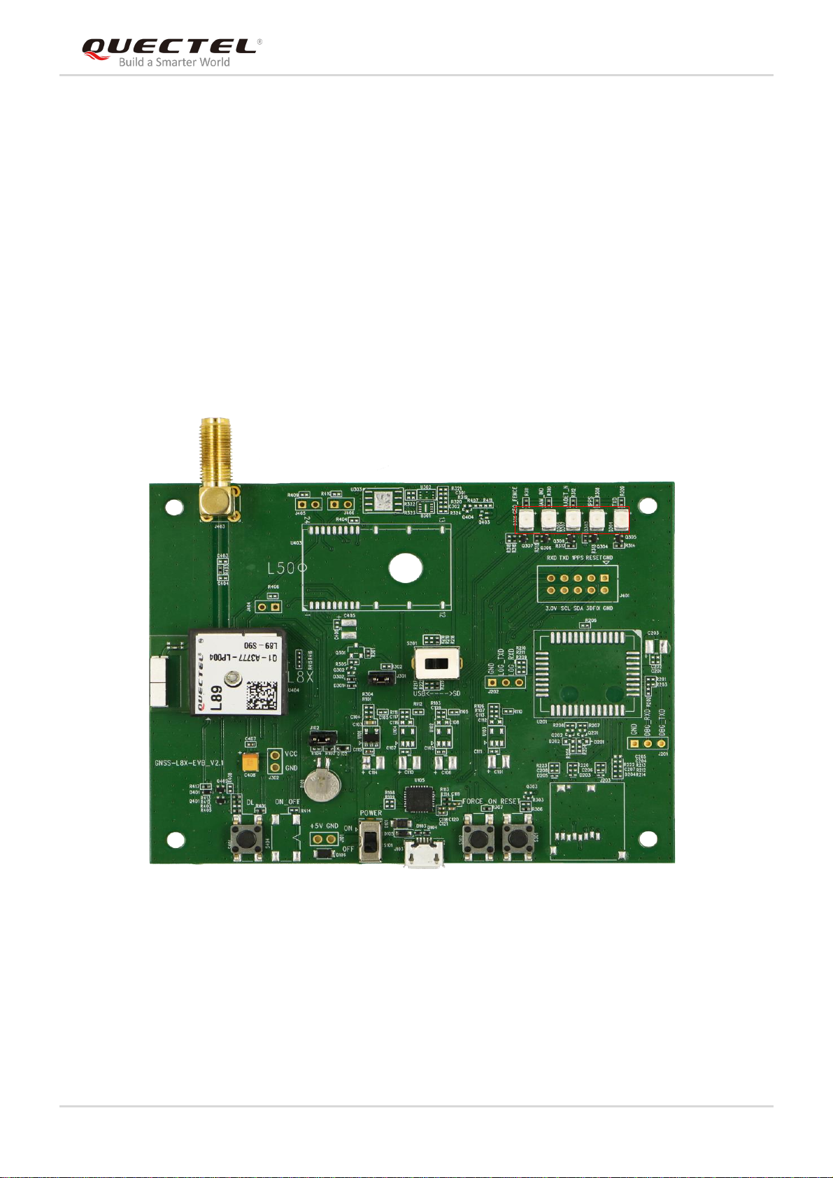
2.1. Top View......................................................................................................................................7
2.2. Key Features...............................................................................................................................8
2.3. EVB Kit Accessories....................................................................................................................9
2.4. EVB and Accessories Assembly...............................................................................................10
3Interface Applications .......................................................................................................................11
3.1. Micro-USB Interface.................................................................................................................. 11
3.2. Antenna Interface......................................................................................................................12
3.3. Switches and Buttons ...............................................................................................................12
3.4. Operation Status Indication LEDs.............................................................................................13
3.5. Test Points.................................................................................................................................14
4EVB Operation Procedures...............................................................................................................15
4.1. Communication through Micro-USB Interface..........................................................................15
4.2. Firmware Downloading.............................................................................................................17
4.2.1. Firmware Downloading in Normal Working Mode .........................................................17
4.2.2. Firmware Downloading in Boot Download Mode...........................................................18
5Usage of Teseo-Suite Pro Tool.........................................................................................................19
5.1. View GNSS Receiver Status.....................................................................................................19
5.1.1. COM Port and Baud Rate Setting..................................................................................19
5.1.2. Explanations of Views and Windows.............................................................................21
5.2. Sending of PSTM Commands ..................................................................................................23
5.3. Support Setting for IRNSS Satellite Histogram ........................................................................23
5.3.1. Opening of the $PSTM Statement Output.....................................................................23
5.3.2. Configuration of the NMEA Protocol for the Teseo-Suite Pro Tool ................................24
6Appendix A Reference.......................................................................................................................26

GNSS Module Series
L89 EVB User Guide
L89_EVB_User_Guide 4 / 26
Table Index
TABLE 1: INTERFACES OF L89 EVB............................................................................................................ 8
TABLE 2: KEY FEATURES OF L89 EVB........................................................................................................ 8
TABLE 3: LIST OF ACCESSORIES ............................................................................................................... 9
TABLE 4: L89 EVB SWITCHES AND BUTTONS.......................................................................................... 13
TABLE 5: OPERATION STATUS INDICATION LEDS................................................................................... 13
TABLE 6: PIN DESCRIPTION OF J106 ....................................................................................................... 14
TABLE 7: TERMS ANDABBREVIATIONS.................................................................................................... 26

GNSS Module Series
L89 EVB User Guide
L89_EVB_User_Guide 5 / 26
Figure Index
FIGURE 1: TOP VIEW OF L89 EVB............................................................................................................... 7
FIGURE 2: EVB KITACCESSORIES............................................................................................................. 9
FIGURE 3: L89 EVB ANDACCESSORIES ASSEMBLY............................................................................... 10
FIGURE 4: MICRO-USB INTERFACE...........................................................................................................11
FIGURE 5: L89 EVB ANTENNA INTERFACE............................................................................................... 12
FIGURE 6: L89 EVB SWITCHESAND BUTTONS....................................................................................... 12
FIGURE 7: OPERATION STATUS INDICATION LEDS................................................................................. 13
FIGURE 8: L89 EVB TEST POINTS............................................................................................................. 14
FIGURE 9: USB PORTS.............................................................................................................................. 15
FIGURE 10: COM PORT SETTING INTERFACE OF QCOM....................................................................... 16
FIGURE 11: STA808X/9X FIRMWARE UPGRADE TOOL CONFIGURATIONS FOR FIRMWARE UPGRADE
............................................................................................................................................................ 17
FIGURE 12: TESEOIII XLOADER TOOL CONFIGURATIONS FOR FIRMWARE UPGRADE....................... 18
FIGURE 13: TESEO-SUITE PRO TOOL INTERFACE.................................................................................. 19
FIGURE 14: MANUAL CONFIGURATION OF THE COM PORT................................................................... 20
FIGURE 15: SIGNAL LEVEL........................................................................................................................ 21
FIGURE 16: SKY VIEW............................................................................................................................... 22
FIGURE 17: MODULE POSITIONING FORM.............................................................................................. 22
FIGURE 18: COMMAND SENDING USING TESEO-SUITE PRO TOOL...................................................... 23
FIGURE 19: PLAYBACK NMEA LOG........................................................................................................... 24
FIGURE 20: NMEALOG PLAYBACK STEP 1.............................................................................................. 24
FIGURE 21: NMEALOG PLAYBACK STEP 2.............................................................................................. 25
FIGURE 22: GENERATED IRNSS SATELLITE HISTOGRAM...................................................................... 25

GNSS Module Series
L89 EVB User Guide
L89_EVB_User_Guide 6 / 26
1Introduction
This document defines and specifies the application of L89 EVB (Evaluation Board) which is a type of
assistant tool used by engineers to develop and test Quectel L89 modules.
1.1. Safety Information
The following safety precautions must be observed during all phases of operation, such as usage, service
or repair of any cellular terminal or mobile incorporating L89 module. Manufacturers of the cellular
terminal should send the following safety information to users and operating personnel, and incorporate
these guidelines into all manuals supplied with the product. If not so, Quectel assumes no liability for
customers' failure to comply with these precautions.
Ensure the use of the product conforms to the local safety and environment
regulations, and is allowed in the country and the environment required.
Keep away from explosive and flammable materials. The use of electronic
products in extreme power supply conditions and locations with potentially
explosive atmospheres may cause fire and explosion accidents.
The product must be powered by a stable voltage source, and the wiring shall
conform to security precautions and fire prevention regulations.
Proper ESD handling procedures must be followed throughout the mounting,
handling and operation of any application that incorporates the module to avoid
ESD damages.

GNSS Module Series
L89 EVB User Guide
L89_EVB_User_Guide 7 / 26
2General Overview
2.1. Top View
The top view of L89 EVB is shown below.
·
B
C D
EF
·
G
H
I
J
K
A
Figure 1: Top View of L89 EVB

GNSS Module Series
L89 EVB User Guide
L89_EVB_User_Guide 8 / 26
Table 1: Interfaces of L89 EVB
2.2. Key Features
The following table shows the detailed features of L89 EVB.
Table 2: Key Features of L89 EVB
SN.
Reference Number
Description
A
S301
RESET button
B
S201
Toggle switch
C
S401
Download button
D
S302
Wake_UP button
E
S101
POWER switch
F
J103
Micro-USB interface
G
D303, D304, D305, D306, D307
Indication LEDs
H
J101
Antenna interface
I
U101
L89 module
J
J106
Test points
Features
Implementation
Power Supply
DC power supply (J103): 4.5V to 5.5V, typically 5.0V
Micro-USB Interface
Power supply and NEMA sentence output
Signal Indication
5 LEDs are available for signal indication
Switches and Buttons
POWER Switch (S101)
RESET (S301)
Physical Characteristics
Size: 100mm ×80mm

GNSS Module Series
L89 EVB User Guide
L89_EVB_User_Guide 9 / 26
2.3. EVB Kit Accessories
Figure 2: EVB Kit Accessories
Table 3: List of Accessories
Items
Description
Quantity
EVB
L89 EVB
1
Cable
USB cable
1
Antenna
Active GNSS antenna
1
USB Flash Drive
USB flash drive (including L89 related
documents, tools, drivers, etc.)
1
Instruction Sheet
Asheet of paper providing instructions for EVB
connection, details of EVB accessories, etc.
1
Others
Bolts and coupling nuts
4 pairs

GNSS Module Series
L89 EVB User Guide
L89_EVB_User_Guide 10 / 26
2.4. EVB and Accessories Assembly
The following figure shows the assembly of L89 EVB and its accessories.
Figure 3: L89 EVB and Accessories Assembly

GNSS Module Series
L89 EVB User Guide
L89_EVB_User_Guide 11 / 26
3Interface Applications
3.1. Micro-USB Interface
The main power is supplied through the Micro-USB interface. The Micro-USB interface is configured to
transfer electrical energy and output NMEAdata to the L89 EVB.
Micro-USB
Interface
Figure 4: Micro-USB Interface

GNSS Module Series
L89 EVB User Guide
L89_EVB_User_Guide 12 / 26
3.2. Antenna Interface
The L89 module can be connected to a dedicated passive or active GNSS antenna, and the L89 module
includes a built-in LNA for improving sensitivity. The antenna interface is configured to connect an
external antenna.
Antenna
Figure 5: L89 EVB Antenna Interface
3.3. Switches and Buttons
The following figure illustrates the switches and buttons of the EVB.
S401
S201
S301S101 S302
Figure 6: L89 EVB Switches and Buttons

GNSS Module Series
L89 EVB User Guide
L89_EVB_User_Guide 13 / 26
Table 4: L89 EVB Switches and Buttons
3.4. Operation Status Indication LEDs
Figure 7: Operation Status Indication LEDs
Table 5: Operation Status Indication LEDs
Part No.
Name
I/O
Description
S301
RESET
DI
When the button is pressed and then released,
the module will be reset.
S302
FORCE_ON
DI
Configured to exit Backup mode of L89 EVB.
S401
DL
DI
Please refer to Chapter 4.2.2 for details.
S101
POWER
PI
Configured to control power supply by using
Micro-USB interface.
S201
USB↔SD
IO
Please keep the switch on USB side
Part No.
Name
I/O
Description
D304
TXD
DO
Flash: The module is started successfully, and either
Micro-USB or SD card interface can be used to
output messages.
Extinct: The module fails to be started.
D303
1PPS
DO
Flash: Successful position fix. The frequency is 1Hz.
Extinct: No position fix.
D307
AADET_N
DO
High: The module has no external active antenna.
Low: The module works by using an internal antenna.

GNSS Module Series
L89 EVB User Guide
L89_EVB_User_Guide 14 / 26
3.5. Test Points
The following figure illustrates the test points of the EVB.
1234
5
6 7 8 9 10
Figure 8: L89 EVB Test Points
Table 6: Pin Description of J106
D305
JAM_IND
DO
High: No signal is interfered when the module works.
Low: Signal is interfered when the module works.
D306
Reserved
DO
Reserved
Pin No.
Signal
I/O
Description
1
GND
-
Ground
2
RESET
DI
System reset
3
1PPS
DO
1 pulse per second
4
TXD
DO
Transmit data
5
RXD
DI
Receive data
6
3.0V
PI
I2C pull up power input
7
SCL
DI
I2C serial clock
8
SDA
IO
I2C serial data
9
3D_FIX
IO
3D-FIX instructions signal

GNSS Module Series
L89 EVB User Guide
L89_EVB_User_Guide 15 / 26
4EVB Operation Procedures
L89 module is upgraded through the UART port (UART_TX/UART_RX) in two methods: firmware
downloading in normal working mode and firmware downloading in boot download mode.
4.1. Communication through Micro-USB Interface
Step 1: Connect the EVB to the PC by using a Micro-USB cable through Micro-USB interface, and then
switch POWER pin to ON state to power on the EVB.
Step 2: Run the USB flash drive on the PC to install the USB driver, where the USB port numbers can be
viewed through the PC Device Manager, as shown below.
Figure 9: USB Ports
Step 3: Install and then use the QCOM tool provided by Quectel to implement the communication
between L89 module and the PC.

GNSS Module Series
L89 EVB User Guide
L89_EVB_User_Guide 16 / 26
The following figure shows the COM Port Setting interface of the QCOM tool. The customers can select
the correct “COM Port” (USB Port shown in the foregoing figure) and set the correct “Baudrate” (the
default value: 9600bps). For more details of usage of the QCOM tool, please refer to
Quectel_QCOM_User_Guide.
Figure 10: COM Port Setting Interface of QCOM

GNSS Module Series
L89 EVB User Guide
L89_EVB_User_Guide 17 / 26
4.2. Firmware Downloading
L89 module supports the firmware downloading in both normal working mode and boot download mode
by using the tools of STA808x/9x Firmware Upgrade and TeseoIII XLoader respectively.
4.2.1. Firmware Downloading in Normal Working Mode
Steps of firmware downloading in normal working mode are as follows:
Step 1: Connect the EVB to a PC by using the USB cable.
Step 2: Switch the POWER pin to ON state to power on the EVB.
Step 3: Run the STA808x/9x Firmware Upgrade Tool and configure the tool as shown below.
Figure 11: STA808x/9x Firmware Upgrade Tool Configurations for Firmware Upgrade
Step 4: Click button and then reset the module to upgrade the firmware.

GNSS Module Series
L89 EVB User Guide
L89_EVB_User_Guide 18 / 26
4.2.2. Firmware Downloading in Boot Download Mode
Steps of firmware downloading in boot download mode are as follows:
Step 1: Connect the EVB to a PC by using the USB cable.
Step 2: Long press DL button (the 3D-FIX/BOOT pin of L89 will be pulled up to connect the VCC pin by
using a 10kΩ resistor), and switch POWER pin to ON state to power on the EVB. Once the high
voltage level of 3D-FIX/BOOT pin has been detected during power-up, the module will enter
bootloader download mode.
Step 3: Release DL button to enable 3D-FIX/BOOT pin of L89 to return to normal floating.
Step 4: Run the TeseoIII XLoader tool and configure the tool as shown below.
a
c
d
b
Figure 12: TeseoIII XLoader Tool Configurations for Firmware Upgrade
Step 5: Click button to upgrade the module.

GNSS Module Series
L89 EVB User Guide
L89_EVB_User_Guide 19 / 26
5Usage of Teseo-Suite Pro Tool
After EVB accessories are assembled, please start the module and the Teseo-Suite Pro tool. The tool can
help users to view the status of GNSS receiver and monitor module calibration result conveniently. For
more details about the tool, please click “Help” and select “User Manual” in the tool interface.
5.1. View GNSS Receiver Status
5.1.1. COM Port and Baud Rate Setting
After the tool is started, the following interface will be displayed.
Figure 13: Teseo-Suite Pro Tool Interface
UART port can be automatically identified by Teseo-Suite Pro tool when the tool is started. If manual
modification is required, steps a to d illustrated in the following figure need to be performed.
Table of contents
Other Quectel Motherboard manuals

Quectel
Quectel LG69T AA User manual

Quectel
Quectel L76 User manual

Quectel
Quectel SC20 User manual

Quectel
Quectel UC20 User manual

Quectel
Quectel LC29D EVB User manual

Quectel
Quectel L30 User manual

Quectel
Quectel LG69T AM User manual

Quectel
Quectel GNSS Module Series User manual

Quectel
Quectel BC95-TE-B User manual

Quectel
Quectel L76C User manual

Quectel
Quectel BC66-TE-B User manual

Quectel
Quectel L10 EVB User manual

Quectel
Quectel LC98S User manual

Quectel
Quectel L80 User manual

Quectel
Quectel Smart EVB G2 User manual

Quectel
Quectel L26-LB User manual

Quectel
Quectel Mini PCIe EVB User manual

Quectel
Quectel HC06U EVB User manual

Quectel
Quectel L86 User manual

Quectel
Quectel UMTS<E EVB User manual