Argal ASTRA Evo DDE Series Installation instructions

OPERATIONS & MAINTENANCE MANUAL
DEALER
For Maintenance
Date of commissioning:
………………………………………………
Position / system reference:
………………………………………………
Service:
………………………………………………

Operations & maintenance manual – ASTRA evo (DDE)
ARGALAIR 2020 | Rev. 6
2
TABLE OF CONTENTS
0. GENERAL DESCRIPTION
0.1 PUMP IDENTIFICATION
0.2 CONNECTIONS CONFIGURATION
0.3 PUMP LABELING
0.4 STANDARDS REFERENCE
0.5 MANUAL INTRODUCTION
0.6 GENERAL NOTES
1. SAFETY: WARNINGS FOR TRANSPORT – INSTALLATION – USE – STOP OF THE PUMP
1.0 TRANSPORT
1.1 RECEIVING INSPECTION
1.2 STORAGE
1.3 FOUNDATION
1.4 BEFORE STARTING THE PUMP
1.5 SUCTION AND DISCHARGE PIPING
1.6 RECOMMENDED INSTALLATION
1.7 FIRST START UP
1.8 OPERATION
1.9 STOP OF THE PUMP
2. SAFETY RISKS
2.0 GENERAL PRESCRIPTIONS
3. MAINTENANCE
3.1 OPERATORS FOR INSTALLATION AND START-UP
3.2 OPERATORS FOR OPERATION AND MAINTENANCE
3.3 OPERATORS FOR REPAIR
3.4 PUMP INSPECTION
3.5 COMPLETE INSPECTION
3.6 TROUBLESHOOTING AND POSSIBLE CAUSES
3.7 PARTS LISTS & RECOMMENDED SPARE PARTS: DDE 030
3.8 PARTS LISTS & RECOMMENDED SPARE PARTS: DDE 060 – 100 – 160
3.9 PARTS LISTS & RECOMMENDED SPARE PARTS: DDE 400 – 650
3.10 RECOMMENDATIONS
3.11 PUMP DISASSEMBY
3.12 PUMP ASSEMBLY
4. SPARE PARTS
5. TECHNICAL DATA
5.1 TECHNICAL DATA
5.2 CAPACITY CURVES
5.3 DIMENSIONS
6. PUMP DISPOSAL
7. WARANTY & REPAIR
8. MANUFACTURER DATA

Operations & maintenance manual – ASTRA evo (DDE)
ARGALAIR 2020 | Rev. 6
3
0. GENERAL DESCRIPTION
If you have purchased an ARGAL pump, follow below instructions and local/national rules for a safe use.
The personnel in charge of installation, operation and maintenance of ASTRA evo pumps must be qualified
to carry out the operations described in this manual.
ARGAL shall not be held responsible for the training level of personnel and for the fact that they are not fully
aware of the contents of this manual.
(**) commercial designation: Santoprene® (ExxonMobil), Geolast® (ExxonMobil) (*1) not recommended
(***) commercial designation: Keyflex® (LG Chem Ltd.), Hytrel® (LG Chem Ltd.)
0.2 CONNECTIONS CONFIGURATION
You can get different options for ASTRA evo pump connections. The standard configuration of the ASTRA
evo series is with the suction placed to the left of the air connection, while the discharge is positioned in the
upper part of the pump, on the left side of the air connection.
0.3 PUMP LABELING
RANGE MODEL MATERIALS CONNECTIONS CONFIGURATION
CHAMBERS VERSION DIAPHRAGM BALLS SEATS O-RING TYPE SUCTION DISCHARGE
DDE
160
WR
N
Y
T
P
V
G
L
L
030
G 1/2"
WR
PP+GFR
N
STD
M
TPV (**)
T
PTFE
P
PP
D
EPDM
G
BSP THREADS
L
SX
L
SX
060 G 1/2" FC PVDF+CF X ATEX H TPE (***) S AISI 316L K PVDF V FKM N NPT THREADS R DX R DX
100 G 1" AL AL F FREE L TPV+PTFE D EPDM S AISI 316L T PTFE I ISO FLANGE F
FRONT
CENTER
F
(*1)
FRONT
CENTER
160 G 1" SS AISI 316L Y TPE+PTFE N NBR A AL N NBR A ANSI FLANGE B
BACK
CENTER
B
BACK
CENTER
400 G 1”1/2 SP
AISI 316L
ELECTROPOLISHED
D EPDM
Z
PE
UHMW
K FFKM C CLAMP (*) V
TOP
CENTER
V
TOP
CENTER
650 G 2"
N NBR
X SPLITTED X SPLITTED
V FKM
Standard configurations:
030÷650 WR_/FC_ : G LL
030÷650 AL_ : G LL
030÷160 SS_/SP_ : G LL / C LL
400÷650 SS_/SP_ : G FB / C FB
AIR
CONNECTION

Operations & maintenance manual – ASTRA evo (DDE)
ARGALAIR 2020 | Rev. 6
4
Each pump is supplied with one or two labels (depending on the pump size) containing the manufacturer’s
data, the model, the descriptive code, the year of manufacture, the serial number and the ATEX
classification (see the paragraph 0.4.1).
Check these data upon receiving the goods. Any discrepancy between the order and the discharge must
be communicated immediately.
In order to be able to trace data and information, the descriptive code, model and serial number of the
pump must be quoted.
The label is placed on the center block:
0.4 STANDARDS REFERENCE
MODEL
MANUFACTURER
DATA
DESCRIPTIVE
CODE
SERIAL NUMBER
ATEX RATING
MANUFACTURING
YEAR

Operations & maintenance manual – ASTRA evo (DDE)
ARGALAIR 2020 | Rev. 6
5
0.4.1 ENVIRONMENTS IN DANGER OF EXPLOSION - ATEX DIRECTIVE
ASTRA evo pumps (ATEX version) fulfill the requirements of ATEX Directive 2014/34/EU with the following
rating:
II 2/2 GD IIB cT4
Equipment group II: machines intended for use on the surface (not in mines).
Category group 2: equipment that guarantee a high level of protection.
II 2/2 GD The first number indicates that the internal space of the equipment is intended to be used to transfer potentially
explosive fluids (see characteristics zone 1 / zone 21). The second number indicates that the external surface of the
equipment is suitable for use in areas where during normal activities the formation of an explosive atmosphere
consisting in a mixture of air and flammable substances in the form of gas, vapor or mist is likely (ZONE 1). The explosive
atmosphere may also be in the form of cloud of combustible dust in the air (ZONE 21: area in which the formation of
an explosive atmosphere is likely to occur occasionally during normal activities).
IIB Group related to fluids classified with IIB excluding the following products (Hydrogen, Acetylene, Carbon Disulfide).
c Non-electrical equipment intended for use in explosive atmospheres, designed according to the criterion of
constructional safety c:
UNI CEI EN ISO 80079-37:2016: Explosive atmospheres - Part 37: Non-electrical equipment for
explosive atmospheres - Non-electrical type of protection constructional safety “c”.
T4 Class of assigned temperature (maximum surface temperature 135°C). The processed fluid temperature must fall
within such class range and the user must comply with the instructions containing in the manual and with the current
laws. Furthermore, the user must take into account the ignition point of the gases, vapors and mists in addition to
clouds of combustible powder in the air existing in the area of use.
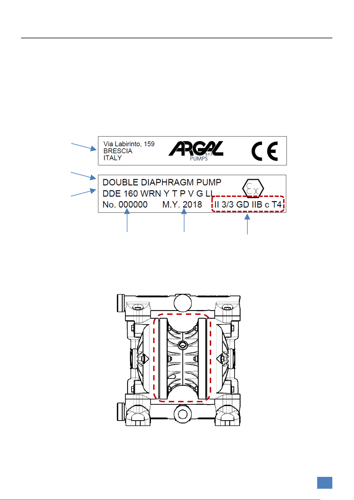
ASTRA evo pumps (STANDARD version) fulfill the requirements of ATEX Directive 2014/34/EU with the following
rating:
II 3/3 GD IIB cT4
Equipment group II: machines intended for use on the surface (not in mines).
Category group 3:equipment that guarantee a normal level of protection.
II 3/3 GD The first number indicates that the internal space of the equipment is intended to be used to transfer potentially
explosive fluids (see characteristics zone 2 / zone 22). The second number indicates that the external surface of the
equipment is suitable for use in areas where during normal activities the formation of an explosive atmosphere
consisting in a mixture of air and flammable substances in the form of gas, vapor or mist is unlikely (ZONE 2) and - if it
occurs - is only of short duration. The explosive atmosphere may also be in the form of cloud of combustible dust in the
air (ZONE 22: area in which the formation of an explosive atmosphere is unlikely to occur during normal activities).
IIB Group related to fluids classified with IIB excluding the following products (Hydrogen, Acetylene, Carbon Disulfide).
c Non-electrical equipment intended for use in explosive atmospheres, designed according to the criterion of
constructional safety c:
UNI CEI EN ISO 80079-37:2016: Explosive atmospheres - Part 37: Non-electrical equipment for
explosive atmospheres - Non-electrical type of protection constructional safety “c”.
T4 Class of assigned temperature (maximum surface temperature 135°C). The processed fluid temperature must fall
within such class range and the user must comply with the instructions containing in the manual and with the current
laws. Furthermore, the user must take into account the ignition point of the gases, vapors and mists in addition to
clouds of combustible powder in the air existing in the area of use.
So it’s specified that the WRN - FCN - ALN - SSN - SPN pumps, according to the ATEX Directive, belong to
category 3, for which they are intended to operate in potentially explosive environments classified as
zone 2. Also available are WRX - FCX - ALX - SSX - SPX pumps, suitable to operate in potentially explosive
environments classified as zone 1.

Operations & maintenance manual – ASTRA evo (DDE)
ARGALAIR 2020 | Rev. 6
6
All ATEX version pumps are covered by the Declaration of Compliance to the Directive 2014/34/EU for use in
potentially Explosive Atmospheres.
CLASSIFICATION VERSION DESCRIPTION SIZE MARKING
“ASTRA evo”
ATEX
ZONE 1
WRX – FCX – ALX
SSX – SPX
Pump made in conductive materials:
•
WRX :
Center Block/ Fluid Chambers/ Manifolds
= PP + Carbon Fiber (PP CFF20);
•
FCX:
Fluid Chambers/ Manifolds = PVDF + Carbon
Fiber (PVDF CFF15);
Center Block = PP + Carbon Fiber (PP CFF20);
•
ALX:
Fluid Chambers/ Manifolds = ALUMINIUM (AL EN
AC46100);
Center Block:
1.
PP + Carbon Fiber (PP CFF20): for model 30,
60, 100, 160;
2.
ALUMINIUM (AL): for model 400, 650.
•
SSX:
Fluid Chambers/ Manifolds
= STAINLESS STEEL (AISI 316L);
Center Block:
1.
PP + Carbon Fiber (PP CFF20): for model 30,
60, 100, 160;
2.
ALUMINIUM (AL): for model 400, 650.
•
SPX:
Fluid Chambers/ Manifolds
= STAINLESS STEEL (AISI 316L electro polished);
Center Block = PP + Carbon Fiber (PP CFF20);
G 1/2"
G 1"
G 1 1/2"
G 2”
II 2/2GD c IIB T4
“ASTRA evo”
STANDARD
ZONE 2
WRN – FCN – ALN
SSN – SPN
Pump made in conductive materials:
•
WRN:
Center Block/ Fluid Chambers/ Manifolds
= PP + Glass Fiber (PP GF30);
•
FCN:
Fluid Chambers/ Manifolds = PVDF + Carbon
Fiber (PVDF CFF15);
Center Block = PP + Glass Fiber (PP GF30);
•
ALN:
Fluid Chambers/ Manifolds = ALUMINIUM (AL EN
AC46100);
Center Block:
1.
PP + Glass Fiber (PP GF30): for model 30, 60,
100, 160;
2.
ALUMINIUM (AL): for model 400, 650.
•
SSN:
Fluid Chambers/ Manifolds
= STAINLESS STEEL (AISI 316L);
Center Block:
1.
PP + Glass Fiber (PP GF30): for model 30, 60,
100, 160;
2.
ALUMINIUM (AL): for model 400, 650.
•
SPN:
Fluid Chambers/ Manifolds
= STAINLESS STEEL (AISI 316L electro polished);
Center Block = PP + Glass Fiber (PP GF30);
G 1/2"
G 1"
G 1 1/2"
G 2”
II 3/3GD c IIB T4
Table 1
0.4.2 MACHINERY DIRECTIVE 2006/42/EC
The
ASTRA evo
is in conformity with the essential health and safety requirements and technical construction
file requirements of the
Machinery Directive 2006/42/EC
. Therefore these pumps are not dangerous for the
operators if used according to the instructions contained within this Manual.

Operations & maintenance manual – ASTRA evo (DDE)
ARGALAIR 2020 | Rev. 6
7
For safety purposes please be sure to read and follow the instructions, particularly the “warnings and
cautions” contained within this Manual before pump installation and operation.
The manufacturer assumes no responsibility for any modification and/or incorrect applications that may
cause damage to the security, the health of people or things in the vicinity of the pump.
All technical data are referred to a “
STANDARD PUMP”
(see TECHNICAL FEATURES) but we remember that -
for a constant technological innovation and quality research - the characteristics reported in this Manual
may change without notice.
The drawings and all the other documents delivered with the machine are the property of the
manufacturer, which reserves all rights and forbids making them available to third parties without his written
consent.
All ARGAL pumps are covered by the following Declaration of Conformity to Machinery Directive
2006/42/EC.

Operations & maintenance manual – ASTRA evo (DDE)
ARGALAIR 2020 | Rev. 6
8

Operations & maintenance manual – ASTRA evo (DDE)
ARGALAIR 2020 | Rev. 6
9
0.5 MANUAL INTRODUCTION
This Use Manual is an integral part of the pump, it is a
“Safety Device”
and contains important information so
that the buyer and his staff can install, use and maintain the pump in a constant state of efficiency.
When installing, operating and maintaining of the pump unit you must strictly follow the Use Manual.
Otherwise injury or life hazard may occur.
In this Instruction Manual are present specific symbols used for the purposes of security and for a proper use
of pump.
All the warnings and cautions will be indicated by the following symbols.
WARNING: this symbol indicates to the personnel that the described operation presents the risk
of exposure to residual dangers (with the possibility of damage to health) if not done in
accordance with the procedures and the safety regulations. If you ignore the warning described
and operate the pump in an improper manner, there is the danger of serious body injury or
death.This signal stands at points in this Instruction Manual of particular importance for
compliance with regulations and directives, for the prevention of damage to destruction of the
complete pumps or its subassemblies.
CAUTION: this symbol indicates to the personnel that the described operation may cause
damage to the machine and/or its components and consequent risks for the operator and/or the
environment if not carried out in compliance with the safety regulations. If you ignore the caution
described and operate the pump in an improper manner, there is the danger of personal injury
or property damage.
NOTE: this symbol provides information about the current pump operation. This symbol indicates
that important directions are contained here.
OBLIGATION AND INDIVIDUAL PROTECTION: these symbols indicate that you must use suitable
individual protections, as the energy status and the type of fluid transferred by the pump, could
create a dangerous condition that occurs during the maintenance operation.
OPERATOR: this qualification requires a complete knowledge and understanding of the
information contained in the Manufacturer’s Use Manual - as well as specific skills on the type
of use.
MECHANICAL MAINTAINER: this qualification requires a complete knowledge and
understanding of the information contained in the Manufacturer's Use Manual, specific skills
necessary to perform the installation and ordinary maintenance - as well as specific skills of
each sector.
EXTRAORDINARY MAINTENANCE: this symbol identifies the actions reserved to the
technical assistance which are carried out only at the manufacturer's workshops.

Operations & maintenance manual – ASTRA evo (DDE)
ARGALAIR 2020 | Rev. 6
10
To indicate the type of danger and damage, the following symbols are also used along with
those mentioned above:
This symbol indicates a DON’T, and will be accompanied by an explanation on something
you must not do.
This symbol indicates a DO, and will be accompanied by instructions on something you must
do in a certain situation.
0.6 GENERAL NOTES
0.6.1 CHARACTERISTICS OF THE PUMPS
ASTRA evo pumps are air-operated, double-diaphragm positive-displacement pumps, designed and
manufactured for pumping fluids that are chemically compatible with the construction materials of the
pump. The characteristics of the fluid (pressure, temperature, chemical reactivity, specific weight, viscosity,
vapor pressure) and the environment must be compatible with the pump characteristics.
The best knower of the fluid is who buys the pump. The buyer is responsible for choosing the materials used
for the parts in contact with the fluid.
The configuration of the pump (wetted parts) is defined in the ordering phase and is indicated on the
nameplate.
ASTRA evo pumps are suitable for pumping corrosive, abrasive, aggressive, flammable, cut-sensitive
chemical fluids, or with solids, such as acids, alkalis, alcohols, solvents, emulsions, oils, fuels, lubricants,
sludge, industrial sewage , enamels, varnishes, glues, water based fluids (containing suspended solids),
additives, detergents.
Chemical composition of the pumped fluid, concentration, temperature, amount of abrasive solids can
radically change the applicability of the configured pump or significantly reduce its duration. ARGAL
assumes no responsibility in this regard.
SOME TYPICAL APPLICATIONS:
INDUSTRY
EXAMPLE OF APPLICATION

Operations & maintenance manual – ASTRA evo (DDE)
ARGALAIR 2020 | Rev. 6
11
AUTOMOTIVE
Filter press feeding. Loading and unloading tanks containing dangerous
liquids. Transfer, dosage and mixing of loose oils, fuels, fuels, coolants, anti
freezes, greases, washing liquids. Industrial sewage handling.
CHEMICAL INDUSTRY
Loading and unloading tanks containing dangerous chemical liquids.
Transfer and distribution of acids, alkalis, alcohols, solvents, latex,
chemicals. Packaging of chemical liquids. Processes of transformation
chemicals. Injection. Unloading of chemical waste (sludge and sludge),
water and chemicals.
Dosing and mixing of chemical additives.
PAINTING
Supply of painting guns (machine filling). Wet cabins water treatment.
Loading and unloading of mixing tanks. Transfer and feeding dosing
systems. Pumpable fluids: glues, additives, paints, ink, latex, resins and
pigments.
TEXTILE
Automatic systems for the production of colors.
PAPER
Transport of glue, sodium silicate, titanium oxide.
OIL&GAS
Transfer lubricating oil, DIESEL fuel, process water and condensation,
sludge. Recirculation and transfer of glycol from tanks.
CONSTRUCTION
Fuel transfer. Concrete batching plants.
Site dehydration. Dosage and mixing of asphalt additives.
Municipal use.
WATER TREATMENT
Waste water discharge and chemical waste. Movement of sludge deriving
from "activated sludge" sludge treatment process. Sludge thickening and
digestion. Filter press feed. Neutralization and flocculation (transfer and
distribution of coagulant, flocculant, acids and alkalis for PH control,
bleach and chemical reagents). Dosing and mixing of disinfectants.
GOLD INDUSTRY
Refining precious metals. Transfer of nitric and hydrochloric acid. Loading
and unloading tanks. Chemical waste discharge (sludge and sewage).
FOODINDUSTRY
(SPN-SPX PUMPS)
Transfer of creams, syrups, dairy products, sauces, butter, ice cream,
yogurt, beverages, flavorings, alcohol, chocolate, vegetable and industrial
oils, animal fats, brines and waste products. Food packaging and dosages.
Filling of wine tanks.
PHARMACEUTICAL INDUSTRY
Transfer of creams, gels, pastes, alcohol, raw chemical products, solvents.
ASTRA evo pumps are self-priming.
The priming time of the pump depends on the continuous and localized losses in suction pipe, which
depend on:
•the suction circuit (total length and pipe diameter)
•specific weight of the pumped fluid
•viscosity of the pumped fluid

Operations & maintenance manual – ASTRA evo (DDE)
ARGALAIR 2020 | Rev. 6
12
The pipes can be empty at start-up. Pumps can be used dry, but it is important to operate at low speed (low
air pressure/flow).
CAUTION: an empty pump should operate at low speeds. During slow operation of the pump the
dry suction lift is better than during high stroke frequency. At high frequency, the efficiency is lower.
The suction lift capacity of a liquid filled pump, however, is much higher.
CAUTION: The long periods of dry run may cause damage to the pump.
DRY RUNNING AT HIGH STROKE FREQUENCY CAUSES PREMATURE WEAR OF THE COMPONENTS!
Dry negative suction refers to intake of water at the temperature of 20°C/68°F.
ASTRA evo pumps cannot be used to generate the vacuum.
The purchaser of the pump must be sure that he has correctly evaluated the chemical-physical
characteristics of the fluid.
Note: The maximum temperature of water in continuous operation (DESIGN TEMPERATURE) depends
on the type of construction materials (indicated on the nameplate).
VERSION MAX TEMPERATURE °C (°F)
WRN-WRX
+60 (+140)
FCN-FCX
+90 (+194)
ALN-ALX*
+100 (+212)
SSN-SSX*
+100 (+212)
SPN-SPX*
+100 (+212)
Table 2
*: for configurations with diaphragms made of TPV the temperature restriction is 90°C (194°F).
The maximum temperature of water in continuous operation depends on the type of construction materials
(indicated on the nameplate) and the environment in which the pump will be installed in.
The AMBIENT TEMPERATURE interval is related to the pump's construction materials (specified on the
identification plate):
VERSION
MIN
TEMPERATURE °C (°F)
MAX
TEMPERATURE °C (°F)
WRN-WRX
-5 (-41)
+40 (+104)
FCN-FCX
-20 (-68)
+40 (+104)
ALN-ALX
-40 (-104)
+40 (+104)

Operations & maintenance manual – ASTRA evo (DDE)
ARGALAIR 2020 | Rev. 6
13
SSN-SSX
-40 (-104)
+40 (+104)
SPN-SPX
-40 (-104)
+40 (+104)
Table 3
Note: For different temperatures consult the ARGAL technical department.
CAUTION: To optimize the pump lifetime we recommend to run at 70% of the maximum
performance of the pump. Running at maximum air pressure/flow continuously may cause
premature wear of the components.
CAUTION: To ensure the operation of the pump in the absence of cavitation must be respected the
following conditions:
•Avoid heavy hydraulic load losses in the suction line, increasing the pipe diameter
and/or decreasing the length of the suction.
•In the presence of high prevalence, hydraulic head losses can be divided on two
pumps, placed in series with appropriate distances depending on the losses of each
length.
•Use the pump by positioning it as low as possible, if there is a high difference in level
between pump and free surface of the fluid to be sucked.
The pumped fluid may contain particles suspended in different dimensions in accordance with the
constructive materials of pump:
MODEL 030 060 100 160 400 650
MATERIAL WR_-FC_- AL_ SS_-SP_ WR_-FC_- AL_ SS_-SP_
WR_-FC_- AL_
SS_-SP_
WR_-FC_- AL_
SS_-SP_
WR_-FC_- AL_
SS_-SP_
WR_-FC_- AL_
SS_-SP_
MAX
DIMENSION
(mm)
3 3,5 3,2 3,8 5,5 6 7 9
Table 4
0.6.2 AIR TREATMENT SYSTEM
WARNING: the pneumatic supply of ASTRA evo series pumps must be carried out with oil-free,
filtered,dry and un lubricated air. Avoid pressure drops by using pipes and controlling elements
having characteristics suitable for the pump.
In case of installation in ATEX zone, the compressor must suck air from outside the area classified as ATEX or
use inert gas.
We recommend to use an appropriate air treatment system in order to maintain the pump’s efficiency.
If the air humidity is high, it can be used an air dryer, to lower the dew point. Otherwise, ice may form at the
silencer, causing the narrowing of the air expelling surface. The possible formation of ice on the muffler

Operations & maintenance manual – ASTRA evo (DDE)
ARGALAIR 2020 | Rev. 6
14
cover is normal, since the temperature of the same can be of several degrees below zero, thus freezing the
humidity present in the air. We recommended to pre-heat the air before it reaches the pump to raise its
dew point.
The air temperature does not exceed 50°C (122°F).
Take care that no dirt or particles can intrude into the pump during the connection, as these can
accumulate inside the pump and can cause malfunctions.
It is recommended to use a filtration of the air by a 5 micron filter to prevent the entry of bulk particles. The
filter removes harmful dirt and moisture from the compressed air supply.
Air quality (according to ISO 8573-1:2010. Contaminants and purity classes):
•Particles class IV;
•Water class IV;
•Oil class IV;
For most demanding applications (H ≥ 40 m.c.w for extended periods) the water content in the air must not
exceed the specifications dictated by class II.
WARNING:Dirt in the air can under unfortunate circumstances be the cause of a premature wear
and/or blockages.
We recommended to configure the pneumatic supply circuit of ASTRA evo series pumps with the following
devices:
1. On-off valve to isolate the pump from the circuit (maintenance);
2. Air filter and pressure regulator with manometer;
3. 3 Ways valve;
4. Flow adjuster valve;
5. Flexible hose;

Operations & maintenance manual – ASTRA evo (DDE)
ARGALAIR 2020 | Rev. 6
15
6. Fittings;
ARGAL AIR REGULATION KIT
The devices n° 2, 3, 4, 5 and all necessary fittings are included in the ARGAL Air regulation KIT, supplied by
ARGAL upon request as an accessory. The device n° 1 (On-off valve) is in charge of the customer/installer.
The maximum air feeding pressure for the ASTRA evo pumps is 8 bar. Higher air pressure can damage the
pump and may cause injury to personnel in vicinity of the pump. The minimum air feeding pressure is 2 bar.
Compressed air supply pipes: minimum EXTERNAL dimensions are reported in the following table.
The maximum length of pipes may be 5m.
MODEL
Ø
air pipe
DDE 030
Ø 6 mm
DDE 060
Ø 8 mm
DDE 100 - 160
Ø 10 mm
DDE 400
Ø 12 mm
DDE 650
Ø 14 mm
Table 5
WARNING:if head and capacity must be high there is the risk that ice accumulates in high
quantity and the pump stops. To avoid this, it is very important to maintain the air quality as
prescribed within this Manual.
WARNING: ice may form into the pneumatic exchanger: SCRUPULOUSLY FOLLOW THE
INSTRUCTIONS WRITTEN IN THIS PARAGRAPH, TO PREVENT THE ICE FORMATION.
0.6.3 OPERATING PRINCIPLE
The ASTRA evo pumps are volumetric.
The suction and discharge cycles are simultaneous at alternating phases.
The operating principle concern the VOLUME VARIATION of two chambers. As shown in the scheme below,
while in a chamber a positive volume variation is observed that correspond to a pressure decrease, in the
second one there is a reduction in volume and therefore an increase in pressure occurs. This causes an
aspiration and a thrust on the fluid respectively.
The operation described above is regulated by the VALVES BALL installed on the ASTRA DDE pumps. The
valves open due to the difference in pressure between the two environments that separate, allowing the
passage of the fluid.

Operations & maintenance manual – ASTRA evo (DDE)
ARGALAIR 2020 | Rev. 6
16
In particular: the overpressure that is created in the chamber (A) (fig.1) closes the suction valve and opens
the discharge valve, so that the fluid is sent to the discharge pipe. The valve opens as soon as the pressure
to which it is subjected exceeds the one existing in the discharge pipe. Simultaneously in the chamber (B),
the pressure decrease causes the opening of the suction valve and the closing of discharge valve.
The flow rate is given exclusively by the product of the number of cycles per unit of time and the volume
aspirated, and then relaunched, at each cycle, so it is adjustable in an extremely precise manner.
This type of pumps allows to confer heads directly proportional to the supply pressure.
A PUMPING CYCLE
The pneumatic distribution system sends compressed air behind one of the two diaphragms (A), which
deforming causes a reduction in volume in the chamber than pushes the fluid towards the discharge circuit.
Simultaneously, the opposite diaphragm (B) is in the intake phase since it is dragged by the shaft that
connects it to the other diaphragm (A) that is under pressure; air present behind it is discharged into the
environment through the flow rate regulator present on the pump, while a pressure drop is created in the
fluid chamber which sucks the fluid from the suction circuit. When the diaphragm (A) under pressure,
reaches the stroke limit, the distributor switches the two inputs to the chamber on the diaphragms air side,
putting diaphragm (B) under pressure and diaphragm (A) in discharge.
When the pump reaches its original starting point, each diaphragm has carried out one air discharge stroke
and one fluid discharge stroke. This sequence of movements makes up a complete pumping cycle.
1. SAFETY: WARNINGS FOR TRANSPORT – INSTALLATION – USE – STOP OF THE
PUMP
0.1 TRANSPORT
•Mount pressure plugs, furnished with the pump, on the hydraulic connections and keep them for a
future use.
•Lift the pump without mechanical stress (shocks, jolts and vibrations can cause permanent
damage).
•For transport on irregular roads, cushion the pump with suitable support plane.
•Blows and impacts may damage parts that are important to machine operation and safety.
SUPPLIED AIR
EXHAUSTED AIR
FLUID DRAWN
FLUID DELIVERED

Operations & maintenance manual – ASTRA evo (DDE)
ARGALAIR 2020 | Rev. 6
17
Note: To lift the pump, use the handle provided on all the ASTRA DDE pump models.
WARNING:The DDE 400 and DDE 650 pumps must not be lifted manually. To lift them it is necessary
to provide special lifting hooks/accessories, to be connected to the pump discharge manifold.
1.1 RECEIVING INSPECTION
•Check the shipment on receipt.
•Check that the packing and the pump are intact and they have not been damaged - make sure
that all parts and accessories listed on the packing list are accounted for.
•Take the Use Manual and operate as described.
1.2 STORAGE
•If the equipment is to be stored prior to installation, place it in a clean location.
•Do not remove the protective covers from the suction, discharge and air connections which have
been fastened to keep pump internals free of debris.
•The pump has to be protected from wetness, coldness, dirtying, UV-radiation.
•Store the pump in an original packaging. The package should be stored raised from the ground, in a
closed, clean and dry environment.
•In the event that the package is not whole at the time of receipt, it is necessary to release the pump
from the package, verify its integrity and restore a new package.
•The storage location must be a closed room with a temperature not lower than -5°C not exceeding
40°C and with a moisture content not exceeding 90%.
•The packing event should not be subjected to shocks, vibrations and overloads.
•Clean the pump thoroughly before installation.

Operations & maintenance manual – ASTRA evo (DDE)
ARGALAIR 2020 | Rev. 6
18
1.3 FOUNDATION
•The pump can be installed without being fixed to a foundation only in case of temporary and short-
term operations.If fixation is needed for an installation, make sure the foundation is able to absorb
vibrations. As option ARGAL provides special anti-vibration rubber devices. It is essential for the
operation of the pump to mount the pump with the feet in a downward direction (see sketch);
•Below the scheme for the possible installations:
Possible installations
1.4 BEFORE STARTING THE PUMP
•Make sure that the pump is installed according to the contents of this manual.
•Before starting the pump is not necessary to fill it with liquid, if not previously agreed in special cases.
•To verify the absence of losses we recommend to conduct a run test to make sure that the pump operates
correctly and does not leak.
•Check the tightening torque of screws. After one week of operation, the torque should be checked again to
prevent leakages.
•Pumps equipped with plastic structural parts require a further tightening of the bodies.
For the following
operations:
-
Trasfer
-
Supply
-
Circolation
-
Injection
-
Evacuation
-
Metering
Mi i
*Note: suspended version to be specified in the request for quotation.
SELF PRIMING
SELF PRIMING TROLLEY
MOUNTED
POSITIVE
SUCTION SUSPENDED *

Operations & maintenance manual – ASTRA evo (DDE)
ARGALAIR 2020 | Rev. 6
19
1.5 SUCTION AND DISCHARGE PIPING
WARNING: The suction and discharge piping should be
flexible
to prevent undue stress
and strain on the pump connections. Alternatively use
flexible joints
between the
discharge/suction connection and any rigid fixed piping.
Rigid piping may cause strong vibration and the manifolds to break. Avoid configuring
the connections with the third character F (i.e. GFF - GBF). It could occur the dripping of the product
pumped onto the pneumatic supply connection.
CONNECTION OF SUCTION PIPE
It is recommended to be very careful during the connection operation of the suction pipe, since just a small
air infiltration will dramatically reduce the suction capability of the pump. Be especially careful during pump
priming. When connecting the suction pipe, following is recommended:
•The suction hose must be non-collapsible, reinforced type as the pumps are capable of generating a moderate
degree of vacuum (the suction power may shrink the hose).
•Do not use pipes with nominal diameter smaller than the diameter of the pump connections to have best
suction capability. For negative suction installation and when pumping viscous fluids, use pipes with nominal
diameter greater than the diameter of the pump connections.
•It is essential that the suction pipe is leak-proof for the pump self-priming operation.
•Position the pump as close as possible to the point of suction. It is better to use a short suction pipe to avoid air
pockets.
•Check that the connections hose-pump are correctly tight, and there are no leaks.
•Avoid installing filters with a solid passage lower than the values stated in the related table. Place filters that
have a filtration surface of at least 20x the nominal section of the pipe.
•In the case of installation of the above mentioned filters, connect a suction pressure monitoring system, in order
to signal those values which may lead to cavitation and sometimes stop the pump when such conditions occur.
CONNECTION OF DISCHARGE PIPE
All components (hose, pipe, valves etc.) on the discharge piping must be designed for PN10.
AIR CONNECTION
•Screw the air hose into the air intake on the central casing of the pump.
•We recommend that the diameter of the flexible hose must conform to the values shown in (Table 6) or above.
•Maximum pipe length between air plant and pump: 5m. If a longer length is required, choose a pipe diameter
that does not cause a pressure drop of more than 0.2 bar between the air pickup point and the pump inlet.
1.6 RECOMMENDED INSTALLATION
USE THE PLANT SOLUTIONS INDICATED IN THE FOLLOWING DIAGRAM

Operations & maintenance manual – ASTRA evo (DDE)
ARGALAIR 2020 | Rev. 6
20
POSSIBLE PLANT SOLUTION
1. Use flexible pipes reinforce with rigid spiral to connect the hydraulic circuit of the pump. Do not use
pipes with nominal diameter smaller than the diameter of the pump connections (a smaller piping
can cause cavitation (suction line) as well as a loss of performance (suction and discharge line). In
case the pipe is too big, the dry suction capacity of the pump can decrease. For negative suction
installation and when pumping viscous fluids, use pipes with nominal diameter greater than the
diameter of the pump connections.
2. Use pulsation damper when the residual pressure ripple is undesirable for the goodness of the
process.
3. Use the 3-way valve on the air supply for starting and stopping of the pump.
4. Use suction and discharge pressure gauges with pressure switches for additional protection. Cut off
the pump when there is an excessive discharge pressure (to protect the system) and an excessive
suction depression (to protect the pump).
5. Use pipe anchoring.
6. Place shut-off valves on both suction and discharge piping for pump isolation. The pump
performance can be adjusted by normal flow control on the discharge side of the system using the
gate valve.
7. Ensure that there are no air pockets in pipeline, they can be a cavitation symptom; the circuit must
be linear and short.
8. Use collector tank around the base of pump to contain leakage. In case of pumping particularly
dangerous fluids, a collection tank equipped with a system that signals, or rather stops the pump, in
the presence of liquid in the tank itself must be installed. Alternatively, the tank can be equipped
with a channel that allows the percolated fluid to be collected. Provide the shielding of the pump
This manual suits for next models
6
Table of contents
Other Argal Water Pump manuals
Popular Water Pump manuals by other brands

America's Best Home Products
America's Best Home Products ABFLC30H Series owner's manual

Liberty Pumps
Liberty Pumps 2LE Series installation manual

Crane
Crane Barnes 3SE3032L Installation and operation manual

GYS
GYS 052321 Instructions of use

HydroAir
HydroAir HA 350 Series Directions for use

AxFlow
AxFlow Aturia ND Series Operation & maintenance manual