MANUALE D’USO ROUTE - rev. 2 - 10/01 pag. 1/15
USE MANUAL
Via Labirinto, 159
25125 BRESCIA - ITALY
CE
TMR SERIES
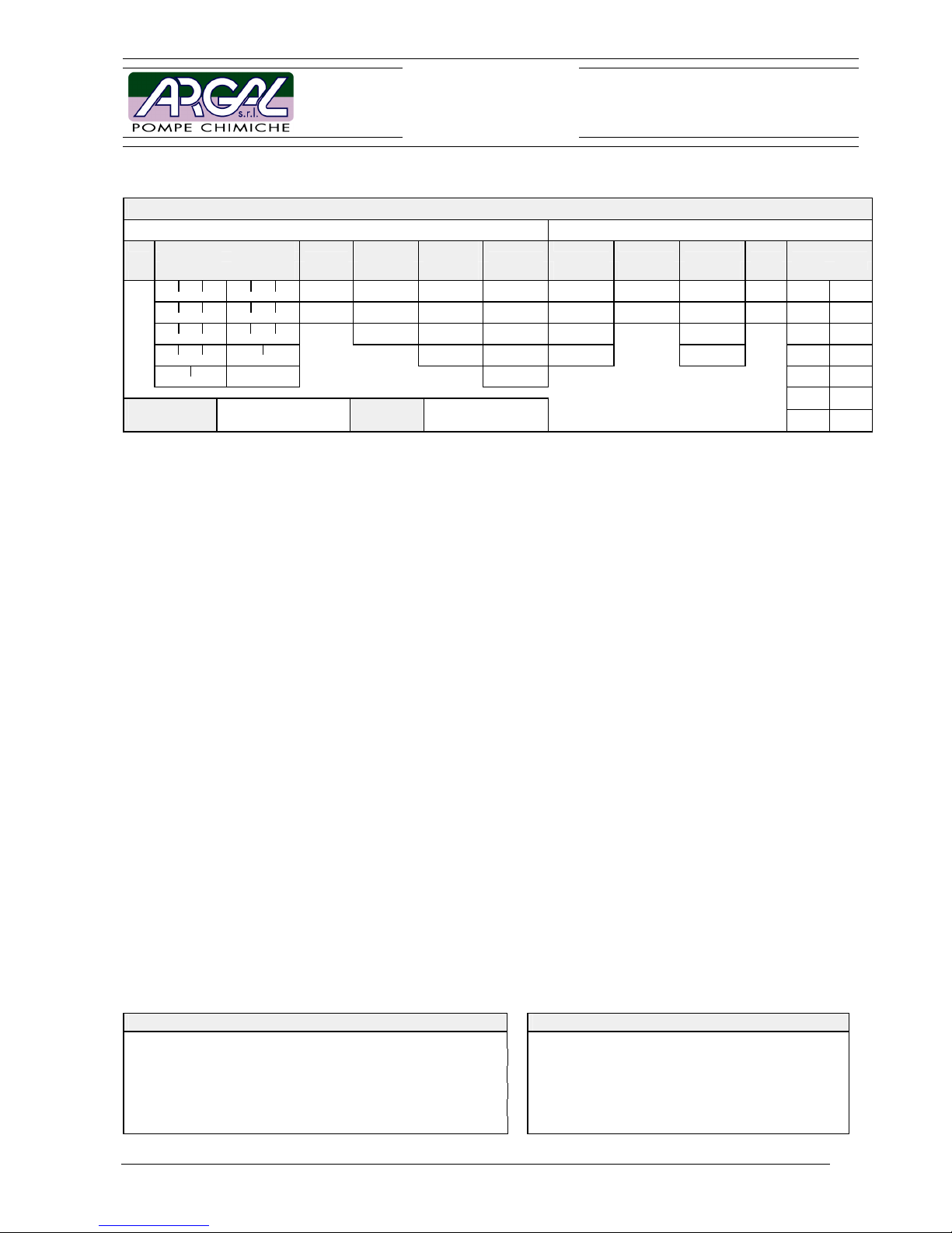
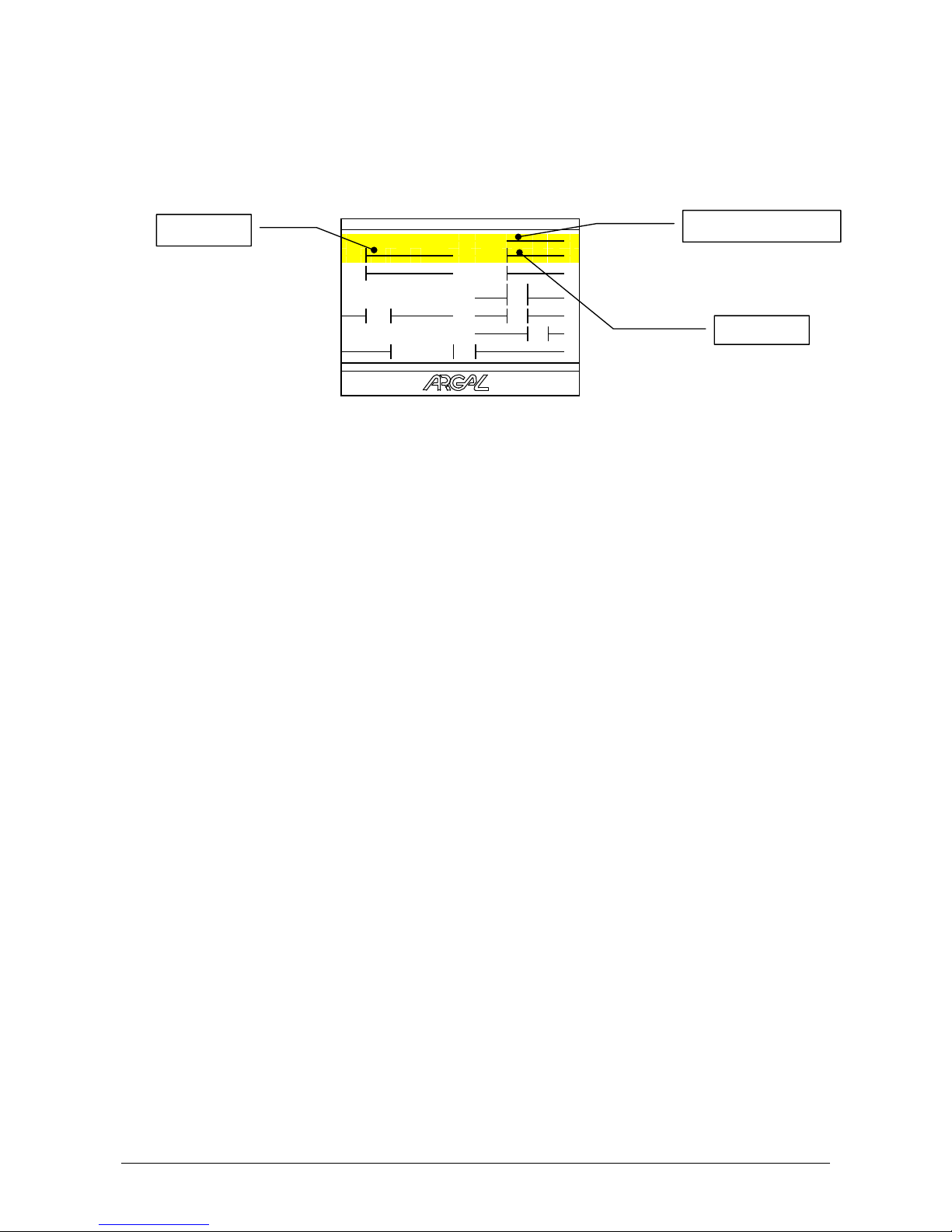
IDENTIFICATION CODE
PUMP DATA MOTOR DATA
model
execution material
O-ring
inside
structure
connections rpm motor voltage/EEx phases powersrange
50Hz 60Hz kW HP
NPSNPSWRV R1 B E 0
06.10 07.11
GFR-PP FPM C/Al2O3 filettate BSP 1450 IEC senza motore 3 fasi 0.55 ¾
NPSNPSGF E X1 N U N
10.10 07.14
CFF-E-CTFE EPDM SiC/Al2O3 filettate NPT
2900 NEMA V std 1 fase 0.75 1
NPSNPSK R2 I S
TMR 10.15 11.15 FFKM C/SiC flangiate ISO
1740
V speciale 1.1 1½
NPSNPX2 A E
16.15 11.23 SiC/SiC flangiate ANSI
3500 EEx 1.5 2
NPNJ
16.20 17.25 flangiate JIS
2.2 3
3 5
Year of
manufacture
Part
number
4 5
1 TABLE OF CONTENTS
1 TABLE OF CONTENTS ....................................................................................................................................... 1
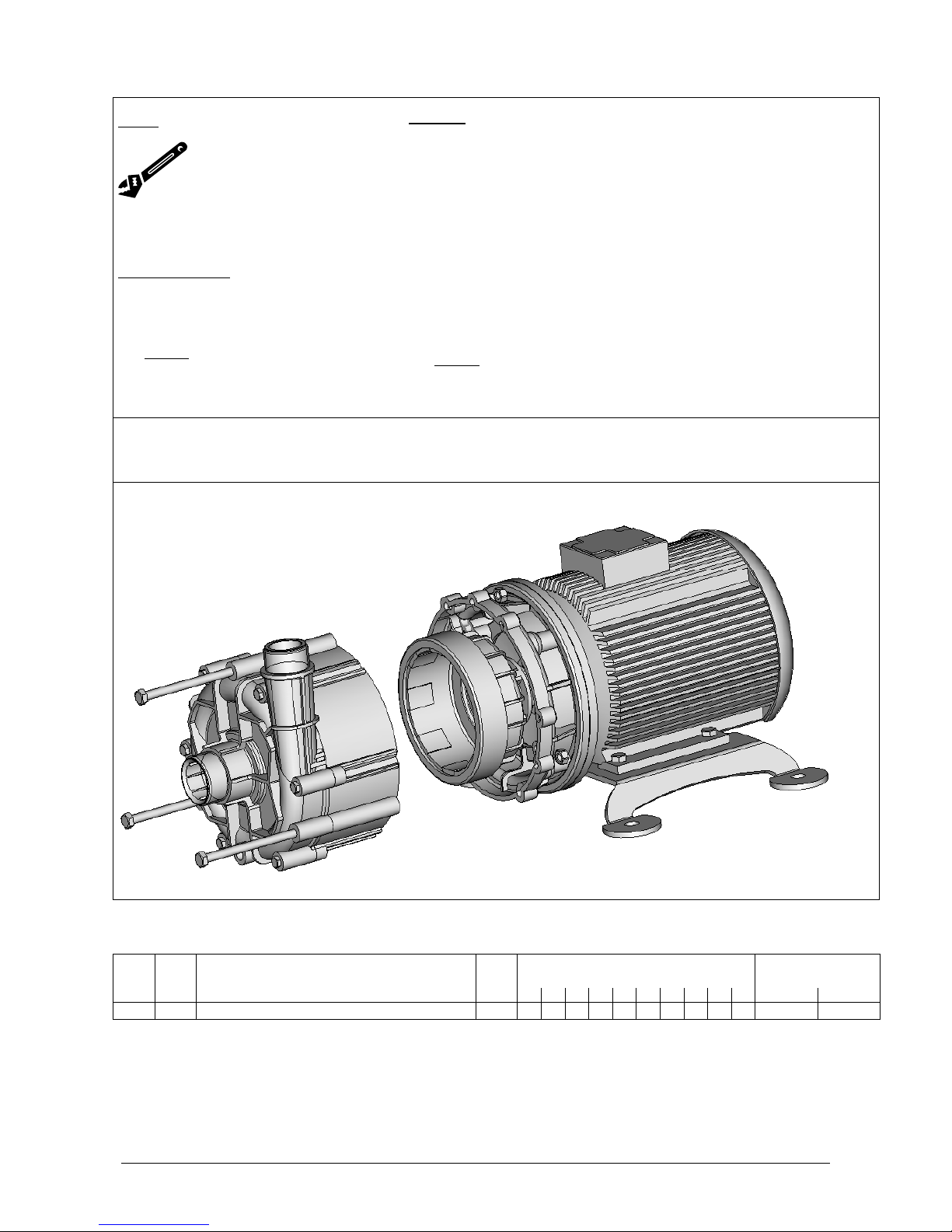
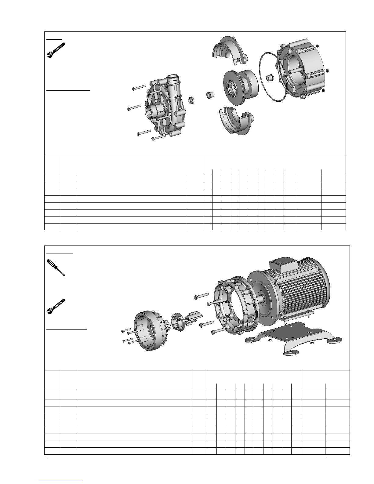
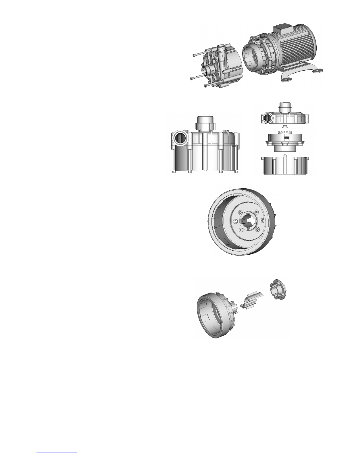
2 DISASSEMBLING SEQUENCE........................................................................................................................... 2
2.1 HYDRAULIC PARTS LEGEND .......................................................................................................................3
2.2 MOTOR PARTS LEGEND ................................................................................................................................3
3 IDENTIFICATION CODES ................................................................................................................................... 4
4 GENERAL NOTES ............................................................................................................................................... 4
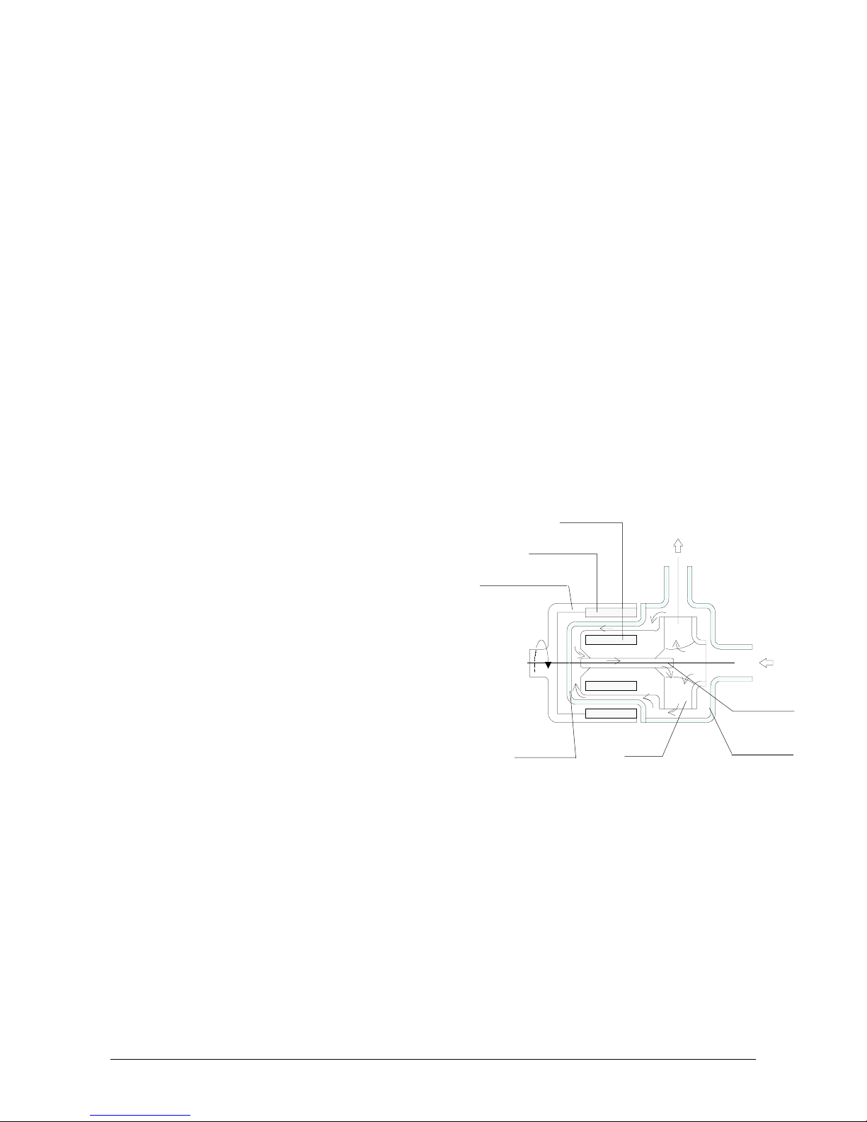
5 OPERATING PRINCIPLE .................................................................................................................................... 5
6 MOTOR ................................................................................................................................................................ 6
7 DRY RUNNING SURVEY .................................................................................................................................... 6
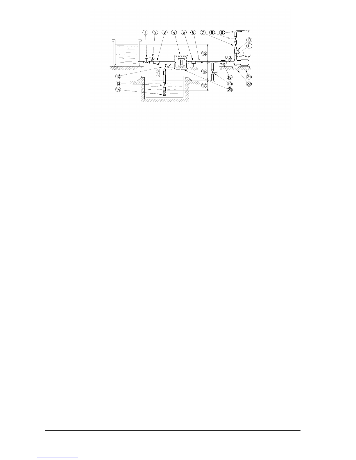
8 INSTRUCTIONS ON INSTALLATION AND USE ................................................................................................ 7
8.1 TRANSPORT .....................................................................................................................................................7
8.2 INSTALLATION................................................................................................................................................7
8.3 START-UP..........................................................................................................................................................8
8.4 USE .....................................................................................................................................................................9
8.5 SHUTDOWN......................................................................................................................................................9
9 MAINTENANCE ................................................................................................................................................... 9
9.1 DISMANTLING .................................................................................................................................................9
9.2 INSPECTION ...................................................................................................................................................10
9.3 ASSEMBLY .....................................................................................................................................................11
10 SAFETY RISKS ............................................................................................................................................. 12
10.1 INSTALLATION AND COMMISSIONING PERSONNEL...........................................................................13
10.2 OPERATORS AND MAINTENANCE PERSONNEL....................................................................................13
10.3 REPAIR PERSONNEL.....................................................................................................................................13
10.4 WASTE DISPOSAL .........................................................................................................................................14
11 IMPROPER USE ........................................................................................................................................... 14
12 OPERATING FAULTS AND POSSIBLE CAUSES ....................................................................................... 14
13 TECHNICAL DATA........................................................................................................................................ 15
14 GENERAL CONDITIONS OF SALE.............................................................................................................. 18
15 MANUFACTURER DATA .............................................................................................................................. 19
for MAINTENANCE DEALER
date of commissioning
position / system reference
service