Argo-Hytos LubMon Connect User manual

Quickstart LubMon Connect
V1.00.13
Read the safety instructions and operating instructions in the manual
prior to commissioning!
For any questions please contact:
ARGO-HYTOS GMBH
Sensors & Measurement division
Industriestraße 9
76703 Kraichtal-Menzingen
Tel. +49-7250-76-0
Fax +49-7250-76-575
E-Mail:info.de@argo-hytos.com

2
The device complies with CE requirements
Read the safety instructions and operating instructions prior to
commissioning!
Note: Illustrations do not always precisely correspond to the original. No legal claim can be derived
due to incorrect information. Product design is subject to change without notice.
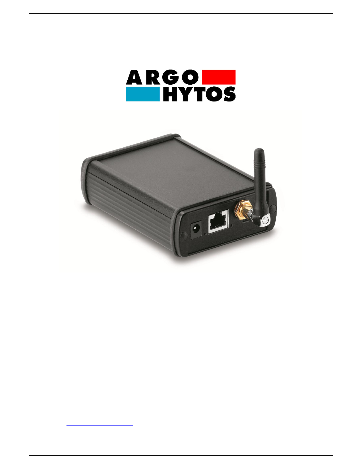
1.Quick Start
The steps that must be executed for commissioning the LubMon Connect gateway are described
below. The following components are necessary for this:
1. Gateway LubMon Connect
2. Connection of compatible sensors:
LubCos H2Oplus II,
LubCos Level,
LubCos Vis+
OPCom II
Analogue sensors using analogue/CAN nodes μCAN.6.ai-SNAP
3. Sensor cable (order number: SCSO 100-5020)
4. Power supply including rubber connector (order number: SCSO 100-5080)
5. Configuration software for LubMon Connect (www.argo-hytos.com)
6. Additionally for longer cabling: CAN standard cable (5-pole, M12), CAN-T pieces (5-pole,
M12), CAN terminating resistors (5-pole, M12)
The configuration software for LubMon Connect can be downloaded from the website www.argo-
hytos.com.
The components must be prepared as follows:
A) Software installation
1. Installation is not required. The individual components of the software package are
executable immediately after the .zip file is unpacked.

3
B) Connecting LubMon Connect to the Internet
2. Connect LubMon Connect to the power supply and then correctly connect your power
supply to line voltage.
3. Now establish a connection between LubMon Connect and the Internet. You can find
detailed information about this in the manual.
C) Sensor connection
4. Make sure that the CAN interface is activated for all the sensors used, that the baud rate is
set to the same known value and that the node IDs of the sensors are all different and
known (the sensor configuration is explained in the respective manuals).
5. Connect the CAN sensor cable to the sensor with the M12x8 connector.
6. Connect the 9-pin CAN-Sub-D cable connector to the corresponding LubMon Connect
interface.
7. Now connect the sensors and the LubMon Connect, if necessary using additional T-pieces
and extension cables (cf.: Manual LubMon Connect).
D) Gateway configuration
8. Connect your computer to the same network as the gateway and start the tool
"Ethernet_Config.exe". Configure the network settings of the gateway according to your
requirements (cf.: Manual LubMon Connect).
9. The tool "RI_Config.exe" can then be used to enter the node ID and the CAN baud rate of
the sensors. (cf.: Manual LubMon Connect).

4
2.Technical data
Data
Range
Unit
Environmental conditions, operation:
Temperature
Humidity
5..50
0…95
°C
% r.H.
Environmental conditions, storage:
Temperature
Humidity
0..60
0…95
°C
% r.H.
Power supply
12…28
V
Power consumption
<0.2 typ.; <0.3 max.
A
CAN interface
Connector
Bus speeds
Protocol
SUB-D9
100 / 125 / 250 / 500
CANopen
-
kBaud
-
Ethernet interface
Connection type
Speed
Protocol
RJ45
10 / 100
UDP
-
MBit
-
GSM
Antenna
Transmission power @ 850/900 MHz
Transmission power @ 1800/1900 MHz
SIM card type
Frequencies
Stub Antenna FME
2
1
Standard SIM card 1.8V / 3V
850 / 900 / 1800 / 1900
(quad-band EGSM)
-
W
W
-
MHz
Optical displays
Power LED
Ethernet LED
Green
Yellow
Supported sensors
LubCos H2Oplus II
LubCos Level200
LubCos Level375
LubCos Level615
LubCos Vis+
OPCOM II
-
-
-
-
-
-

5
Fig. 2.1: Dimensional drawing

6
3.Installation
In order to facilitate integration and to make the connection as simple as possible, several
attachment options are provided (cf.: Fig. 3.1). In addition, a corresponding cable can be used to
connect an external antenna. An optimal transmission position can be achieved through an
appropriate choice of cable length.
Fig. 3.1: Installation options for LubMon Connect
Please note the following guidelines with respect to the installation position and location of the
device in order to ensure proper function.
LubMon Connect is not protected against penetration by moisture and dust, meaning that
a suitably shielded installation location should be chosen.
The necessary environmental conditions and power supply must be provided (see Chapter
4 –Technical data).
Network set-up and connection of the power supply must be performed by qualified
personnel in order to ensure correct functioning!

7
4.Electrical connection
The electrical installation may only be performed by qualified professionals
(trained electricians) with the power off and in accordance with the applicable
standards and guidelines. The manufacturer will accept no responsibility in the
event of improper installation.
4.1.General, plus safety notices
Comply with national and international guidelines for setting up electrical equipment.
Power supply in accordance with EN50178, SELV, PELV, VDE0100-410/A1.
De-energise the system for the installation and connect the device as follows:
Fig. 4.1: Pin assignments for the CAN interface
The permissible operating voltage is between 12V and 28 VDC. The sensor cable must be
shielded. Pin 8 und Pin 9 are for the power supply of LubMon Connect and not for the power
supply of the connected bus devices.
Pin 1 ---
Pin 2 CAN-L
Pin 3 GND
Pin 4 ---
Pin 5 SHIELD
Pin 6 ---
Pin 7 CAN-H
-------- Galvanically isolated --------
Pin 8 supply + (24VDC)
Pin 9 supply –
(view of connector from the outside)
Other manuals for LubMon Connect
1
Table of contents
Popular Network Router manuals by other brands

AMTC
AMTC WR3005 user guide

Ensemble Designs
Ensemble Designs Avenue 9430 quick start guide

ZyXEL Communications
ZyXEL Communications VMG8825 quick start guide

D-Link
D-Link DIR-819 user manual

Planet Networking & Communication
Planet Networking & Communication WGSW-2840 user manual

Inseego
Inseego Wavemaker FG2000 quick start guide