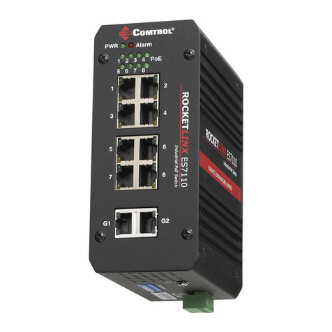
Comtrol WR7802-XT Series User manual

WR7802-XT Series
Industrial Managed PoE Cellular Router
2 - Gigabit PoE Plus Ports
2 - Gigabit SFP Ports
User Guide
Beta Version

Copyright Notice
Comtrol and RocketLinx are trademarks of Comtrol Corporation.
Microsoft and Windows are trademarks of Microsoft Corporation.
FireFox is a trademark of Mozilla Foundation.
PuTTY is a copyright of Simon Tatham.
Other product names mentioned herein may be trademarks and/or registered trademarks of their respective owners.
First Edition, June 27, 2018
Copyright © 2017-2018. Comtrol Corporation.
All Rights Reserved.
Comtrol Corporation makes no representations or warranties with regard to the contents of this document or to the
suitability of the Comtrol product for any particular purpose. Specifications are subject to change without notice.
Some software or features may not be available at the time of publication. Contact your reseller for current product
information.
Document Number: 2000638 Rev A
Beta Version

Table of Contents RocketLinx WR7802-XT Series User Guide: 2000638 Rev. A - 1
Table of Contents
Introduction .......................................................................................................................................... 5
Basic Factory Default Settings................................................................................................................... 5
R&TTE Directive 1999/5/EC......................................................................................................................... 6
Federal Communications Commission (FCC) Statement .................................................................... 6
FCC Radiation Exposure Statement......................................................................................................... 7
Safety Precautions ........................................................................................................................................ 7
General Notification ................................................................................................................................... 7
Environment and Housing ......................................................................................................................... 8
Installation.................................................................................................................................................. 8
Hardware Installation ........................................................................................................................ 9
Safety Precautions ........................................................................................................................................ 9
General Notifications.................................................................................................................................. 9
Environment and Housing Notifications................................................................................................. 10
Installation Notifications ......................................................................................................................... 10
Insert the SIM Card .................................................................................................................................... 11
Connect the Antenna .................................................................................................................................. 11
Mounting an SMA-Type External Antenna ............................................................................................ 12
Mounting an N-Type External Antenna ................................................................................................. 12
How to Select an External Antenna ........................................................................................................ 12
Antenna Alignment .................................................................................................................................. 13
Lightning Arrestor.................................................................................................................................... 13
Connect the Power ...................................................................................................................................... 13
Connect the Digital Output (Dry Relay Output).................................................................................. 14
Ground the WR7802-XT .............................................................................................................................. 14
Connect the Ethernet Ports ...................................................................................................................... 15
Connect SFP Transceivers (Ports 3-4).................................................................................................... 16
Mount the WR7802-XT ................................................................................................................................ 16
LED Descriptions......................................................................................................................................... 17
Reset Button ................................................................................................................................................. 17
Using PortVision DX .........................................................................................................................19
PortVision DX Overview ............................................................................................................................ 19
PortVision DX Requirements.................................................................................................................... 20
Installing PortVision DX............................................................................................................................ 20
Configuring the Network Settings .......................................................................................................... 21
Checking the Firmware Version.............................................................................................................. 23
Uploading the Latest Firmware............................................................................................................... 25
Uploading Firmware to Multiple WR7802-XT Switches ..................................................................... 26
Adding a New Device in PortVision DX ................................................................................................. 27
Using Configuration Files ......................................................................................................................... 28
Saving a Configuration File ..................................................................................................................... 28
Loading a Configuration File ................................................................................................................... 28
Using the LED Tracker............................................................................................................................... 29
Customizing PortVision DX ...................................................................................................................... 30
Beta Version

2 - RocketLinx WR7802-XT Series User Guide: 2000638 Rev. A Table of Contents
Table of Contents
Accessing RocketLinx Documentation from PortVision DX ............................................................. 30
How to Download Documentation ........................................................................................................... 31
How to Open Previously Downloaded Documents .................................................................................. 32
Configuration Using the Web User Interface..............................................................................33
System Requirements................................................................................................................................. 33
How to Log Into the WR7802-XT .............................................................................................................. 33
Web User Interface ................................................................................................................................... 33
Secure Web User Interface....................................................................................................................... 36
Diagnosing a Login Failure....................................................................................................................... 39
Introduction to the Web Interface........................................................................................................... 39
Status Web Pages......................................................................................................................................... 41
Status | Information Page ....................................................................................................................... 42
Status | Network Flow Page ................................................................................................................... 44
Status | ARP Table Page ......................................................................................................................... 45
Status | DHCP Client List Page ............................................................................................................. 45
System Web Pages ....................................................................................................................................... 46
System | Basic Settings Page.................................................................................................................. 46
System | IP Settings Page ....................................................................................................................... 47
System | DHCP Server Page ................................................................................................................... 49
System | Time Settings Page .................................................................................................................. 50
System | Relay Settings Page ................................................................................................................. 51
System | DDNS Settings Page ................................................................................................................ 51
System | Traffic Shaping Page................................................................................................................ 53
System | Outbound Firewall Submenu .................................................................................................. 53
System | Outbound Firewall | Src (Source) IP Filtering Page....................................................... 54
System | Outbound Firewall | Dest (Destination) IP Filtering Page ............................................ 54
System | Outbound Firewall | Src (Source) Port Filtering Page ................................................... 55
System | Outbound Firewall | Dest (Destination) Port Filtering Page ......................................... 55
System | Inbound Filtering Page ............................................................................................................ 56
System | NAT Settings Submenu ........................................................................................................... 57
System | NAT Settings | Port Forwarding Page............................................................................. 57
System | NAT Settings | DMZ Page................................................................................................58
System | NAT Settings | Advanced Page ........................................................................................ 59
Power Over Ethernet Pages...................................................................................................................... 59
Power over Ethernet | PoE Control Page ............................................................................................... 59
Power over Ethernet | PoE Schedule Page............................................................................................. 62
Power over Ethernet | PoE Status Page................................................................................................. 63
Switch Configuration Pages ..................................................................................................................... 64
Switch Configuration | Port Status Page ............................................................................................... 64
Switch Configuration | Port Control Page.............................................................................................. 65
Switch Configuration | VLAN Configuration Page................................................................................ 66
System Configuration | Rate Control Page ............................................................................................ 68
Switch Configuration | Port Statistics Page........................................................................................... 69
Traffic Prioritization Pages ...................................................................................................................... 70
Traffic Prioritization | QoS Setting Page ............................................................................................... 70
Traffic Prioritization | CoS-Queue Mapping Page .................................................................................71
Traffic Prioritization | DSCP-Queue Mapping Page.............................................................................. 72
Multicast Filtering Pages .......................................................................................................................... 73
Multicast Filtering | IGMP Snooping Page............................................................................................ 74
Multicast Filtering | IGMP Query Page................................................................................................. 75
Beta Version

Table of Contents RocketLinx WR7802-XT Series User Guide: 2000638 Rev. A - 3
Table of Contents
Network Redundancy Pages..................................................................................................................... 76
Network Redundancy | STP Configuration Page................................................................................... 77
Network Redundancy | STP Port Configuration Page .......................................................................... 79
Network Redundancy | STP Information Page...................................................................................... 80
Network Redundancy | Redundant Ring Configuration Page .............................................................. 81
Network Redundancy | Redundant Ring Information Page.................................................................. 82
Network Redundancy | Redundant Gateway Page................................................................................ 83
Network Redundancy | VRRP Page........................................................................................................ 85
Cellular Pages............................................................................................................................................... 87
Cellular | Cellular Basic Settings Page .................................................................................................. 87
Cellular | SIM Security Settings Page.................................................................................................... 89
Cellular | Mobile Manager Settings Page .............................................................................................. 90
VPN Pages ..................................................................................................................................................... 91
VPN | VPN Status Page .......................................................................................................................... 92
VPN | OpenVPN Client Settings Page ................................................................................................... 93
VPN | OpenVPN Server Settings Page .................................................................................................. 95
VPN | VPN Port Forwarding Page ......................................................................................................... 97
VPN | VPN Certificate Page ................................................................................................................... 98
VPN | IPsec Settings Page ...................................................................................................................... 98
Security - Port Security Page ................................................................................................................. 101
Management Pages.................................................................................................................................... 102
Management | OPCUA Settings Page .................................................................................................. 103
Management | Remote Settings Page................................................................................................... 104
Management | SMTP Settings Page..................................................................................................... 107
Management | Login Settings Page...................................................................................................... 108
Management | Firmware Upgrade Page ..............................................................................................110
Management | Configuration File Page ............................................................................................... 111
Management | LLDP Configuration Page............................................................................................112
Tools Pages.................................................................................................................................................. 113
Tools | System Log Page........................................................................................................................ 113
Tools | Ping Watchdog Page .................................................................................................................. 114
Tools | Ping Page.................................................................................................................................... 115
Save Page..................................................................................................................................................... 115
Logout Page ................................................................................................................................................ 115
Reboot Page ................................................................................................................................................ 115
Configuration Using the Command Line Interface (CLI) ......................................................116
Overview...................................................................................................................................................... 116
Accessing the CLI through an SSH Client........................................................................................... 116
Accessing the CLI through PortVision DX .......................................................................................... 117
CLI Introduction........................................................................................................................................ 118
Command List......................................................................................................................................... 118
Using SHOW Commands .......................................................................................................................... 120
Using SET Commands .............................................................................................................................. 123
How to Set the Device Name.................................................................................................................. 123
Set the Cellular Settings ........................................................................................................................ 124
Set the PoE Settings............................................................................................................................... 124
Set the Switch Settings .......................................................................................................................... 125
Using DELETE Commands...................................................................................................................... 126
Beta Version

4 - RocketLinx WR7802-XT Series User Guide: 2000638 Rev. A Table of Contents
Table of Contents
Beta Version

RocketLinx WR7802-XT Series User Guide: 2000638 Rev. A Basic Factory Default Settings - 5
Introduction
The RocketLinx WR7802-XT Series is an industrial grade Cellular LTE router with two PoE and two SFP
fiber Ethernet ports. The WR7802-XT contains a Long Term Evolution (LTE) module with two SIM slots,
which supports for up to 100M DL and 50M DL. In addition, the two Gigabit 802.3at PoE ports support up to
30W to PoE devices. The two 100/1000BASE-X SFP fiber ports provide great flexibility for field installations.
The WR7802-XT supports Cellular communications features, such as multiple ports to LTE NAT routings,
dual SIM standby, SNMP, LLDP and Mobile Manager Server for remote monitoring. The OPC UA is designed
for industrial machine to machine (M2M) communication, a popular protocol for industrial automation and
M2M applications.
The WR7802-XT also provides different types of VPN Client technology and 1-1 OpenVPN Server for secure
M2M connectivity. The WR7802-XT supports dual 54V (48-57VDC) input, Digital Output and a wide
operating temperature of -40~75° with an IP30 enclosure.
Basic Factory Default Settings
The following table provides an overview of the default settings on the WR7802-XT.
Standard Details
Cellular Standard
3GPP Release 9 Long Term Evolution (LTE), 2x2 DL-MIMO
LTE category 3: Maximum 100 Mbps DL, 50 Mbps UL
Backward compatible with UMTS/HSPA+/GSM/GPRS/EDGE
WR7802-XT-E
Bands
LTE: 800/900/1800/2600/2100 MHz, FDD-Band (20,8,3,7, 1)
UMTS/HSPA+: 900/1800/2100 MHz, FDD-Band (8,3,1)
GSM/GPRS/EDGE: 900/1800 MHz
WR7802-XT-X
Bands
LTE: 700/700/850/AWS (1700/2100)/1900 MHz; FDD-Band (13,17,5,4,2)Tri Band
UMTS/HSPA+: 850/AWS (1700/2100)/1900 MHz; FDD-Band (5,4,2);Quad Band
GSM/GRPS/EDGE: 850/900/1800/1900 MHz
Features Factory Default Settings
Username admin
Password admin
Model Name WR7802-XT
LAN IP Address (Default)
IP Address 192.168.250.250
Subnet Mask 255.255.255.0
IP Gateway Address 192.168.250.1
DHCP Server Settings
DHCP Server Enable
DHCP IP Range Start 192.168.250.100
Beta Version

6 - R&TTE Directive 1999/5/EC RocketLinx WR7802-XT Series User Guide: 2000638 Rev. A
Introduction
Detailed specifications for the RocketLinx WR7802-XT Series are available on the Comtrol web site.
R&TTE Directive 1999/5/EC
The product may be operated in all European Union countries. The R&TTE (1999/5/EC) Directive requires
that the apparatus bears the CE mark as conformation of compliance with the R&TTE Directive.
A formal declaration of R&TTE for wireless products is available on our web site. Different products may
conform to different standards of Health & Safety, EMC, Radio and other specific standards. You can
download the formal document for the product from the Web site or request it from our Sales/Technical staff.
Federal Communications Commission (FCC) Statement
This equipment has been tested and found to comply with the limits for a Class B digital device, pursuant to
Part 15 of the FCC Rules. These limits are designed to provide reasonable protection against harmful
interference in a residential installation. This equipment generates uses and can radiate radio frequency
energy and, if not installed and used in accordance with the instructions, may cause harmful interference to
radio communications. However, there is no guarantee that interference will not occur in a particular
installation. If this equipment does cause harmful interference to radio or television reception, which can be
determined by turning the equipment off and on, the user is encouraged to try to correct the interference by
one of the following measures:
• Reorient or relocate the receiving antenna.
• Increase the separation between the equipment and receiver.
• Connect the equipment into an outlet on a circuit different from that to which the receiver is connected.
• Consult the dealer or an experienced radio/TV technician for help.
This device complies with Part 15 of the FCC Rules. Operation is subject to the following two conditions: (1)
This device may not cause harmful interference, and (2) this device must accept any interference received,
including interference that may cause undesired operation.
FCC Caution: Any changes or modifications not expressly approved by the party responsible for compliance
could void the user's authority to operate this equipment.
DHCP IP Range End 192.168.250.200
DHCP Subnet Mask 255.255.255.0
DHCP Gateway Address 192.168.250.1
Diagnostic CLI (Reserved for Engineering Diagnostics)
Console Type 3-pin (Tx, Rx, GND)
Baud Rate 115200
Cellular (3G/LTE)
SIM Socket Default is SIM 1
Cellular Redundancy Disabled by default. This feature is only available
when two SIM cards are inserted.
Cellular Connect Automatically after the SIM is inserted and the
WR7802-XT is receiving power.
Others SIM Settings Determined by your SIM card settings.
SIM Security None
Features Factory Default Settings
Beta Version

RocketLinx WR7802-XT Series User Guide: 2000638 Rev. A FCC Radiation Exposure Statement - 7
Introduction
FCC Radiation Exposure Statement
This equipment complies with FCC radiation exposure limits set forth for an uncontrolled environment. To
avoid the possibility of exceeding radio frequency exposure limits, you shall beep a distance of at least 100cm
between you and the antenna of the installed equipment. This transmitter must not be co-located or operating
in conjunction with any other antenna or transmitter.
The availability of some specific channels and/or operational frequency bands are country
dependent and are firmware programmed at the factory to match the intended destination. The
firmware setting is not accessible by the end user.
Safety Precautions
General Notification
• Only operate the device according to the technical specifications. You can find this information in the
product data sheet, Quick Installation Guide, and the User Guide.
• Read the installation instructions before connecting the system to the power source.
• Only trained and qualified personnel should be allowed to install, replace, or service this device.
• This device is designed for operation with extra-low voltage (SELV). Connect the unit only to DC power
source 54V (50-57VDC) that complies with the safety extra-low voltage (SELV) requirements in IEC/EN
60950 based safety standards. (Not supported on the 110V input model.)
Connect a power supply that corresponds to the type of your device. For power connection, make sure the
following requirements are met:
• The DC power circuit of the product is usually not an isolated design circuit. In practice, it is suggested to
use an isolated DC power design PSU for field installations. Besides the PSU selection, good digital/earth
grounding is also important before powering on the system.
• The Power Supply conforms to the over-voltage category I or II.
• The output voltage of the AC/DC to DC Power Supply conforms to the range of the input voltage of the
device.
• The connection cables used are permitted for the specified electronic voltage, current, wire diameter and
temperature range. (Wire Diameter of AC voltage is at least 0.75mm, AWG18. For DC voltage, it is at
least 1.0mm, AWG16.)
• Follow the power installation instructions in this guide, which indicates the input voltage, pin
assignment, connection circuit and notices.
• The Power Supply must be properly installed, including grounding and other notices which are defined in
the User Guide.
• Only power on the supply voltage to the device if the housing is closed, the terminal blocks are wired up
correctly and the terminal blocks are connected.
• The equipment must be grounded. Ground the device before connecting the cables, antennas and power
supply. The grounding of the equipment and DC Power Supply may be different in some applications, if
this is case, you must ground them separately.
• Contact the appropriate electrical inspection authority or an electrician if you are uncertain that suitable
grounding is available.
Beta Version

8 - Environment and Housing RocketLinx WR7802-XT Series User Guide: 2000638 Rev. A
Introduction
Environment and Housing
•Hot surface. Avoid touching the device while it is operating.
• Only operate the device at the specified ambient temperature and humidity. The temperature of the
surrounding air means a distance of up to 5cm from the device. When installing multiple devices within
the cabinet, leaving space between the devices is mandatory for better heat dispersement.
• Install the device in the vertical position, with the antenna connections pointing upward.
• Install the device in a cabinet or in an operating site with limited access. The metal cabinet will filter the
radio signals. Use an extended antenna cable and install the external antenna in a free space that helps
provide a better radio signal.
• Only technicians authorized by the manufacturer are permitted to open the housing. Without the
manufacturer permission, opening the housing means the product is not covered under warranty and not
responsible for any unexpected risk.
Installation
If you are installing the wireless equipment in the field box or outdoor area, for your safety as well as others’,
please seek assistance from a professional installer who has received safety training on the hazards involved.
Keep safety as well as performance in mind when selecting your installation site, especially where there are
electric power and phone lines.
Please note the following things as well:
• Do not use a metal ladder;
• Do not work on a wet or windy day;
• Wear shoes with rubber soles and heels, rubber gloves, long sleeved shirt or jacket.
• If you are installing the equipment in an indoor office or factory, make sure that the device and power
source are properly grounded. A professional wireless IT Engineer can provide advice for the AP location,
channel and field plan to get better performance and coverage.
• Connect the equipment after verifying that the cabinet meets the appropriate IP degree of protection.
• Read the radio output power, receiver sensitivity, antenna gain specifications before installation. The
shipped product and antenna conforms to the R&TTE Directive and is allowed for use in all European
countries. You can read the related technical specifications from the product data sheet or User Guide.
• When installing external antennas, the Radio Output power and antenna gain value must meet the
regulations of the country.
• When the system is operational with a high gain antenna, avoid standing directly in front of it. Strong RF
fields are present when the transmitter is on.
• When the system is operational with a high gain antenna for short distance transmission, adjust the radio
output lower. Strong output power with a high gain antenna is not a proper installation method for short
distance transmission.
• You are responsible for undertaking suitable lightning protection.
• Install over voltage protector devices on every outdoor Ethernet cable.
• Protect each antenna installed outside with lightening protection devices, for example, a lightening
arrester.
Note that Field EMD (Lightning) DAMAGE IS NOT COVERED UNDER WARRANTY.
Beta Version

RocketLinx WR7802-XT Series User Guide: 2000638 Rev. A Safety Precautions - 9
Hardware Installation
There are two models available that support different areas of the world:
• WR7802-XT-E, which supports GSM bands
• WR7802-XT-X, which supports US bands
Note: Both models are simply referred to as the WR7802-XT unless there is information for a specific model.
You can use the following subsections to install the RocketLinx WR7802-XT Series.
•Safety Precautions
•Insert the SIM Card on Page 11
•Connect the Antenna on Page 11
•Connect the Power on Page 13
•Connect the Digital Output (Dry Relay Output) on Page 14
•Ground the WR7802-XT on Page 14
•Connect the Ethernet Ports on Page 15
•Connect SFP Transceivers (Ports 3-4) on Page 16
•Mount the WR7802-XT on Page 16
•LED Descriptions on Page 17
•Reset Button on Page 17
Safety Precautions
Please read the following safety precautions before installing the WR7802-XT.
•General Notifications
•Environment and Housing Notifications on Page 10
•Installation Notifications on Page 10
General Notifications
Adhere to the these general notifications:
• Only operate the WR7802-XT according to the technical specifications. You can find this information in
the product data sheet on the web site, Quick Installation Guide, and this User Guide.
• Read the installation instructions before connecting the WR7802-XT to the power source.
• Only trained and qualified personnel should be allowed to install, replace, or service the WR7802-XT.
• The WR7802-XT is designed for operation with extra-low voltage (SELV). Connect the unit only to DC
power source 54V (48-57VDC) that complies with the safety extra-low voltage (SELV) requirements in
IEC/EN 60950 based safety standards. (Not supported on the 110V input model.)
Connect an appropriate power supply that meets the WR7802-XT power specifications. Before connecting and
applying power to the WR7802-XT, make sure the following requirements are met:
• The DC power circuit of the WR7802-XT is not an isolated design circuit. In practice, we recommend using
an isolated DC power design PSU for field installations. Do not power on the WR7802-XT without an
appropriate PSU and following proper grounding methods.
• The power supply conforms to the Over-Voltage Category I or II.
Beta Version

10 - Environment and Housing Notifications RocketLinx WR7802-XT Series User Guide: 2000638 Rev. A
Hardware Installation
• The output voltage of the AC/DC to DC power supply conforms to the input voltage range of the WR7802-
XT.
• Cables (wire) must be appropriate for the specified electronic voltage, current, wire diameter and
temperature range. Remember, the minimum wire diameter of AC voltage is at least 0.75mm(AWG18).
The minimum for DC voltage is at least 1.0mm (AWG16)).
• Follow the power installation instructions in this guide, which indicates the input voltage, pin
assignment, connection circuit and notices.
• Only power on the supply voltage to the WR7802-XT if the WR7802-XT housing is closed, the terminal
blocks are wired correctly and the terminal blocks are connected.
• The WR7802-XT MUST be grounded. Ground the WR7802-XT before connecting the cables, antennas and
power supply. The grounding WR7802-XT and DC power supply may be different in some applications, if
this is case, you must ground them separately.
• Contact the appropriate electrical inspection authority or an electrician if you are uncertain that suitable
grounding is available.
Environment and Housing Notifications
•Hot surface. Avoid touching the WR7802-XT while it is operating.
• Only operate the WR7802-XT at the specified ambient temperature and humidity. The temperature of the
surrounding air means a distance of up to 5cm from the WR7802-XT. When installing multiple devices
within the cabinet, leaving space between the devices is mandatory for better heat dispersement.
• Install the WR7802-XT in the vertical position, with the antenna connections pointing upward.
• Install the WR7802-XT in a cabinet or at an operating site with limited access. A metal cabinet will filter
the radio signals. Use an extended antenna cable and install the external antenna in a free space that
helps provide a better radio signal.
• Only technicians authorized by the manufacturer are permitted to open the WR7802-XT housing. Without
the manufacturer’s permission, opening the housing means the product is not covered under warranty
and not responsible for any unexpected risk.
Installation Notifications
If you are installing the WR7802-XT in a field box or outdoor area, for your safety as well as others’, seek
assistance from a professional installer who has received safety training on the hazards involved. Keep safety
as well as performance in mind when selecting your installation site, especially where there are electric power
and phone lines.
Please note the following things as well:
• Do not use a metal ladder;
• Do not work on a wet or windy day;
• Wear shoes with rubber soles and heels, rubber gloves, long sleeved shirt or jacket.
• If you are installing the WR7802-XT in an indoor office or factory, make sure that the WR7802-XT and
power source are properly grounded. A professional wireless IT Engineer can provide advice on the AP
location, channel, and field plan to get the best performance and coverage.
• Connect the WR7802-XT after verifying that the cabinet meets the appropriate IP degree of protection.
• Read the radio output power, receiver sensitivity, antenna gain specifications before installation. The
shipped product and antenna conforms to the R&TTE Directive and is allowed for use in all European
countries. You can read the related technical specifications from the product data sheet found on the web
site or User Guide.
• When installing external antennas, the radio output power and antenna gain value must meet the
regulations of the country.
• When the system is operational with a high gain antenna, avoid standing directly in front of it. Strong RF
fields are present when the transmitter is on.
Beta Version

RocketLinx WR7802-XT Series User Guide: 2000638 Rev. A Insert the SIM Card - 11
Hardware Installation
• When the system is operational with a high gain antenna for short distance transmission, adjust the radio
output lower. Strong output power with a high gain antenna is not a proper installation method for short
distance transmission.
• You are responsible for undertaking suitable lightning protection.
• Install over-voltage protector devices on every outdoor Ethernet cable.
• Protect each antenna installed outside with lightening protection devices, for example, a lightening
arrester.
Note: FIELD EMD (LIGHTNING) DAMAGE IS NOT COVERED UNDER WARRANTY.
Insert the SIM Card
The WR7802-XT provides dual external SIM (Subscriber Identity
Module) sockets to store the Cellular Nano SIM card. The WR7802-XT
only supports the Nano SIM card, which fits into the Nano SIM
carrier tray that slides into the SIM slots. The illustration shows the
types of SIM cards available.
If you want to use both SIM sockets, you should insert both SIM cards
into the WR7802-XT before applying power. After applying power, you
can enable the Cellular Redundant option and configure SIM 2 as
startup or backup SIM socket using the Cellular Basic Settings web
page.
Note: The Cellular Redundant option is only available if you insert
two SIM cards into the sockets. If you only insert one, DO NOT
enable Cellular Redundant.
Use the following procedure to insert the SIM card.
Note: The WR7802-XT cannot be powered on when inserting the SIM cards. Later when you power on the
WR7802-XT it takes approximately 1 minute to start up and searches for SIM card in SIM slot 1.
1. Remove the two screws that secure the front plate of dual SIM socket.
2. Remove the SIM carrier tray.
Note: The SIM 1 is the default SIM socket.
3. Place SIM card into the carrier, aligning the angled corner with the angled corner of the tray.
4. Gently insert the SIM card into the SIM slot.
After completing the installation, if the Cellular connection is not connected, go to the Status | Information
web page to check the Cellular status and settings.
Connect the Antenna
The WR7802-XT supports up to two antenna
sockets and two LTE antennas are shipped with the
product.
• Antenna A is the LTE-Aux antenna
• Antenna B is the LTE-Main antenna
Note: Leave the dust cap on unconnected antennas.
The antennas shipped with the product are a wide-
temperature design; however, they are not water-
proof. If you want to install it in outdoor area, use
water-proof outdoor antennas.
Beta Version

12 - Mounting an SMA-Type External Antenna RocketLinx WR7802-XT Series User Guide: 2000638 Rev. A
Hardware Installation
The antennas meet these specifications.
The antennas are easy to connect, simply align the antenna on the connector and turn the antenna clockwise
to lock it into place.
Note: To remove the antenna, turn it counter-clockwise.
If you are installing the WR7802-XT in a high vibration environment, you may want to connect it with an
extended radio cable antenna.
If installing the WR7802-XT in a weatherproof cabinet to protect it from water, rain or other reasons, we
recommend mounting its antennas outside the cabinet.
Mounting an SMA-Type External Antenna
If the default antenna is not suitable for your environment, you can purchase an external antenna for your
environment. When selecting an SMA-type external antenna, you must choose an antenna that supports the
correct band in your country for radio transmission.
Mounting an N-Type External Antenna
If the default antenna is not suitable for your environment, for example an outdoor area, you can purchase an
external water-proof N-Type antenna. When selecting an N-type external antenna, you must choose the
correct frequency band of the antenna and it must conform to the radio band you connected.
The WR7802-XT requires an N-Type external antenna, which is an SMA to N-Type connector or RF cable.
Remember that the WR7802-XT antenna connector is an RP-SMA female that connects to RP-SMA male
cable.
How to Select an External Antenna
Normally, the antenna that is shipped with the WR7802-XT works well in most indoor applications. If you
need to install the WR7802-XT in a low signal environment and want to install an external antenna, consult
with your system integrator to choose a suitable external antenna. Remember you will need an SMA-type or
N-Type connector for your application. Different antennas support different bands, polarization and different
ranges of coverage.
Keep the following in mind when selecting an external antenna:
• Gain: Affects the system performance.
• Direction: Typical types include: Omni-Directional or Directional antenna. Check the antenna zone in its
specification.
Frequency Range 824 - 894MHz 900 - 960MHz 1710 - 1880MHz 1910 - 2170MHz
Peak Gain 1.5dBi 1.0dBi 2.0dBi 4.0dBi
Average Gain -2.5dBi -3.5dBi -2.5dBi -2.0dBi
Voltage Standing
Wave Ratio (VSWR) 4.0: 1 maximum
Polarization Linear, vertical
Impedance 50 Ω
Connector RP SMA plug (Reverse-Polarity Sub Miniature version A)
Beta Version

RocketLinx WR7802-XT Series User Guide: 2000638 Rev. A Antenna Alignment - 13
Hardware Installation
• Connector: Make sure you choose the correct connection type. is, for example N-Type, SMA Male/Female.
Antenna Alignment
Use the following procedure to align your antenna.
1. Follow the antenna installation guide to install the antenna properly.
2. Connect your laptop to the Ethernet port and if necessary, install a Cellular Speed Test utility on your
laptop or connect to the carrier provider’s web page, as some carriers provide an utility on their web site.
3. Adjust the antenna location, run the Speed Test utility to check the result after changing the location or
direction.
Lightning Arrestor
If you install an external antenna in outside area, we recommend installing a lightening arrestor to avoid an
environment attack through the antenna. A lightening arrestor protects the insulation and conductors of the
system from the damaging effects of lightning.
Note: Before installing an external antenna, make sure that the antenna can support a 3G connection. Most of
the high gain external antennas are installed in higher place than the AP, you should get a low power
loss antenna cable in advance. If installing the AP in a metal field box, connect an extended antenna
cable to outside the box to avoid the Radio lost.
Connect the Power
The following table provides WR7802-XT electrical specifications.
The WR7802-XT supports redundant power supplies if you connect both PWR1 and PWR2. The WR7802-XT
accepts a positive power source. If both power inputs are connected, the WR7802-XT is powered from the
highest connected voltage. The WR7802-XT does not support reverse polarity protection.
The DC power circuit of the WR7802-XT is not an isolated design circuit. In practice, we recommend using an
isolated DC power design PSU for field installations. Do not power on the WR7802-XT without an appropriate
PSU and following proper grounding methods.
Note: Power should be disconnected from the power supply before
connecting it to the WR7802-XT. Your screw driver blade can
inadvertently short the terminal connections to the grounded
enclosure.
Use the following procedure to connect the power to the WR7802-XT.
1. Connect the DC power inputs by inserting the positive and negative
wires (12-16AWG) into the PWR+ and PWR- contacts using the
following wiring drawing.
Note: Tighten the wire-clamp screws to prevent the wires from coming loose.
Electrical Specifications Value
Power Input
Voltage DC1/DC2
IEEE 802.3af 54V (48-57VDC)
IEEE 802.3at 54V (50-57VDC)
Maximum PoE
Power/Port
IEEE 802.3af 15.4W
IEEE 802.3at 31W
Power Budget PWR1/PWR2 66W @ 54V
Power
Consumption
Without PD load (maximum) 11W
PoE with PD load (maximum) 76W
++ +
-- -
PWR1 PWR2 DO
Beta Version

14 - Connect the Digital Output (Dry Relay Output) RocketLinx WR7802-XT Series User Guide: 2000638 Rev. A
Hardware Installation
2. If you are not going to connect digital output, make sure that you tighten the power connector screws into
the housing so that the power connector is secure.
Connect the Digital Output (Dry Relay Output)
The WR7802-XT provides one digital output (dry relay output) on the terminal block connector on the bottom
of the WR7802-XT.
You can configure link failure using one of the WR7802-XT user interfaces.
Digital output relay contacts are energized (open) for normal operation
and close for fault conditions. The digital output relay contacts support up
to 1A at 24VDC. Do not apply voltage and current higher than the
specifications.
1. Insert the positive and negative wires (12-24 AWG) into V+ and V-.
2. Tighten the wire-clamp screws to prevent the wires from coming loose.
3. Make sure that you tighten the power connector screws into the
housing so that the power connector is secure.
Ground the WR7802-XT
Connect a ground wire between the chassis and earth ground
using 12-24AWG wire to ensure that the WR7802-XT is not
damaged by noise or electrical shock.
1. Loosen the ground screw on the bottom of the WR7802-XT.
2. Insert the ground wire.
3. Tighten the ground screw after the ground wire is connected.
Note: The WR7802-XT MUST be properly grounded. Connect the Ethernet cable, Antenna, extended antenna
cable and Ground before powering on the system.
AC Power Input
AC Power Input
Power Supply
48-57*VDC
Power Supply
48-57*VDC
V-
V+
V-
V+
12 - 16AWG Wire
12 - 16AWG Wire
Wiring Positive Power Supplies
* Depending on the PoE standard.
++ +
-- -
PWR1 PWR2 DO
Beta Version

RocketLinx WR7802-XT Series User Guide: 2000638 Rev. A Connect the Ethernet Ports - 15
Hardware Installation
Connect the Ethernet Ports
There are four Gigabit Ethernet ports, two standard RJ45, IEEE802.3 at 30W High Power PoE ports and two
SFP Fiber ports for LAN.
You can use the following information to connect Ethernet cables between the WR7802-XT Ethernet ports and
the network nodes.
See Connect SFP Transceivers (Ports 3-4) on Page 16 for information about SFP installation.
The RJ45 Ethernet ports automatically detect the signal from the connected devices to negotiate the link
speed and duplex mode (half- or full-duplex). Auto MDI/MDIX allows you to connect another switch, hub, or
workstation without changing straight-through or crossover cables. Crossover cables cross-connect the
transmit lines at each end to the received lines at the opposite end.
Connect one side of an Ethernet cable into any switch port and connect the other side to your attached device.
The LNK/ACT LED is lit when the cable is correctly connected. Always make sure that the cables between
the switches and attached devices (for example, switch, hub, or workstation) are less than 100 meters (328
feet) and meet these requirements.
•10BASE-T: Category 3 or higher cable
•100BASE-TX: Category 5 or higher cable
•1000BASE-TX: Category 5 or higher cable
Note: Comtrol recommends using CAT 5E/CAT 6 cables in harsh environments. STP (Shielded Twisted Pair)
cable is preferred. If the WR7802-XT is installed in a harsh environment, part of the EMS protection is
based on STP cable.
TX D1+ 1
TX D1- 2
RX D2+ 3
RX D2- 6
BI D3+ 4
BI D3- 5
BI D4+ 7
BI D4- 8
1 RX D2+
2 RX D2-
3 TX D1+
6 TX D1-
4 BI D4+
5 BI D4-
7 BI D3+
8 BI D3-
Straight-Through Cabling
TX D1+ 1
TX D1- 2
RX D2+ 3
RX D2- 6
BI D3+ 4
BI D3- 5
BI D4+ 7
BI D4- 8
1 RX D2+
2 RX D2-
3 TX D1+
6 TX D1-
4 BI D4+
5 BI D4-
7 BI D3+
8 BI D3-
Crossover Cabling
10/100BASE-TX 1000BASE-TX
Beta Version

16 - Connect SFP Transceivers (Ports 3-4) RocketLinx WR7802-XT Series User Guide: 2000638 Rev. A
Hardware Installation
Connect SFP Transceivers (Ports 3-4)
The WR7802-XT provides two SFP ports that
accept standard mini GBIC DDM SFP
transceivers that support 100BASE-FX/
1000BASE-X.
To ensure system reliability, Comtrol
recommends using Comtrol certified SFP
Transceivers.
1. Plug the SFP transceiver into the SFP fiber
transceiver.
2. Connect the transmit channel to the receive
channel at each end.
3. Check the direction/angle of the fiber transceiver and the fiber cable.
Note: This is a Class 1 Laser/LED product. Do not stare at the Laser/LED Beam.
The default speed setting is 1000Mbps. If you want to use a 100M SFP Fiber transceiver, you MUST change
the speed to 100Mbp in management interface first.
Multi-Mode cables should not exceed 2KM and Single-Mode cables should not exceed 30km.
Mount the WR7802-XT
You can use the following procedure to mount the WR7802-XT on a DIN rail or on the wall. The DIN rail clip
is already attached to the WR7802-XT. If the DIN rail clip is not screwed onto the WR7802-XT, follow the
instructions and the figure below to attach DIN rail clip to the WR7802-XT.
The SFP cage is 2 x1 design.
1. Insert the upper end of DIN rail clip into the back of DIN rail
track from its upper side.
2. Lightly push the bottom of DIN rail clip into the track.
3. Verify that the DIN rail clip is tightly attached on the track.
4. To remove the WR7802-XT from the track, reverse the steps
above.
DIN Rail Mounting
Beta Version

RocketLinx WR7802-XT Series User Guide: 2000638 Rev. A LED Descriptions - 17
Hardware Installation
LED Descriptions
This subsection provides information about the WR7802-XT LEDs.
Reset Button
The WR7802-XThas a reset button that you can use to reboot the WR7802-XT or reset the configuration to the
factory default.
The Reset button is located on the front panel of the WR7802-XT below the second SFP port.
LED Indication Blinking On Off
PWR PWR1/PWR2 Status N/A Valid power applied No power
GF Fiber Port GF1/GF2 Status GF is activating GF is linked up No link
PoE PoE Output Status N/A Delivering PoE power No PD is attached
ETH Eth1/Eth2 Status Port is
activating Port is linked up Port not linked up
DO Digital Output Status N/A
The Relay is ON. It
may indicate the
alarm of specific
events.
The Relay is OFF
R Boot Status Booting LTE connected Boot finished
SYS System Status N/A Power on Power off
Reset Button Description
Depress 0-3 Seconds This reboots the WR7802-XT without changing the
configuration.
Depress > 7 Seconds This loads the factory default configuration values into the
WR7802-XT including the IP address.
Beta Version

18 - Reset Button RocketLinx WR7802-XT Series User Guide: 2000638 Rev. A
Hardware Installation
Beta Version
This manual suits for next models
2
Table of contents
Other Comtrol Network Router manuals