Argo AT Series Technical Document

"AT" SERIES ELECTRIC HOT WATER BOILERS
FOR FORCED HOT WATER
InSTALLATIOn MAnUAL AnD OPERATInG InSTRUCTIOnS
P/N I80, Rev. A [05/08]
An ISO 9001-2000 Certied Company
ARGO (Technical Support)
2201 Dwyer Avenue
Utica, NY 13501
(Corporate Sales)
85 Middle Road
Dunkirk, NY 14048
www.argocontrols.com

2
INSTALLATION MANUAL AND OPERATING INSTRUCTIONS
TABLE OF CONTENTS
Safety Symbols ....................................................2
Warnings ..............................................................3
Introduction...........................................................3
Product Description..............................................3
Voltage Rating Tables...........................................4
Installation Procedure...........................................5
Design of Water Circulating System.....................6
Connecting Supply and Return Piping..................6
Connecting Electrical Power Supply.....................8
Wiring Diagrams................................................. 11
Thermostat Installation.......................................15
Startup and Seasonal Maintenence ...................15
Troubleshooting..................................................16
Maintenance ......................................................17
Parts List - 2 Element Electric Boilers ...............18
Parts List - 4 Element Electric Boilers ................19
Additional Wiring Diagrams................................20
Modular Boiler Piping .........................................23
Troubleshooting..................................................24
"AT" Series Boiler Dimensions ...........................27
Homeowner's Reference Table ..........................28
KEEP THIS MANUAL NEAR BOILER
RETAIN FOR FUTURE REFERENCE
16027 Tested For 30 LBS.
ASME
Working Pressure
! !
! !
!!
SAFETY SYMBOLS
The following dened symbols are used throughout
this manual to notify the reader of potential hazards
of varying risk levels.
DANGER
Indicates an imminently hazardous situation
which, if not avoided, WILL result in death or
serious injury.
WARNING
Indicates a potentially hazardous situation
which, if not avoided, COULD result in death
or serious injury.
CAUTION
Indicates a potential hazardous situation
which, if not avoided, MAY result in minor or
moderate injury. It may also be used to alert
against unsafe practices.
IMPORTANT: Read the following instructions
COMPLETELY before installing!!

3
INTRODUCTION
This manual is intended to familiarize the installer
and user of the Electric Hydronic Block with its
installation, operation and maintenance so as to
assure its normal trouble free operation.
Argoelectricboilersaredesignedandmanufactured
with quality components for maximum life and
durability and require minimum service. To insure
a satisfactory installation it is imperative that the
instructions be followed carefully before operating
the heating system. Failure to do so may result in
breach of warranty.
PRODUCT DESCRIPTION
The Electric Hydronic Block is a heating device that
converts electrical energy to heat energy through
the medium of water. The simplied theory of this
conversion is as follows:
Electrical Energy x Conversion Factor = Energy
– Or –
Kilowatts Of Electricity Used Per Hour x 3412 = British
Thermal Units (Btuh) Available Per Hour For Heating.
This information is the basis used to establish Elec-
tric Hydronic Block ratings (See Table 1 on page 4).
Since the conversion process requires no combus-
tion, the boiler operates with the highest possible
efciency.
The Electric Hydronic Block is constructed with
a cast iron boiler that conforms to the American
Society of Mechanical Engineers (ASME) Boiler &
Pressure Vessel Code. The interior design allows
just enough water to be present for proper heating
elementoperation- noexcesswater isstoredwhich
wouldcauseundersirablethermallossesandlonger
recovery times.
Thecontrolsystemisassembledinamodularpack-
age thus keeping the overall size and weight of the
ElectricHydronicBlocktoaminimum.Theconstruc-
tionoftheentireElectricHydronicBlockconformsto
Canadian Standards Association (CSA) Standards
for Safety for Electric Boilers.
! !
! !
WARNINGS
WARNING
1.BOILERSIZINGISCRUCIAL.Themaximum
hourlyheatlossforeachheatedspaceshould
be calculated in accordance with the proce-
dures describes in The Hydronics Institute
(I=B=R) manual H-22 (Heat Loss Calculation
Guide), or by any other method which is suit-
ablefor local conditions,providedtheresults
are in substantial agreement. Select the ap-
propriate boiler based on accurate heat loss
calculation.DONOTOVERSIZETHEBOILER,
ASSIZINGISCRITICALFORIN-FLOORRADI-
ANT HEAT APPLICATIONS.
2.Keepboilerareaclearandfreefromcombus-
tible materials, gasoline and other ammable
vapors and liquids.
3. DO NOT obstruct air openings to the boiler
room.
4. Modication, substitution or elimination
of factory equipped, supplied or specied
components may result in property damage,
personal injury or the loss of life.
5.TOTHEOWNER: Installationand serviceof
this boiler must be performed by a qualied
installer.
6. TO THE INSTALLER: Leave all instructions
with the boiler for future reference.
7. When this product is installed in the Com-
monwealth of Massachusetts the installation
must be performed by a licensed plumber or
licensed gas tter.*
* In other areas, consult your local codes.
WARNING
All installations of boilers should be done
only by a qualied expert and in accordance
with the appropriate Argo manual. Installing
a boiler or any other electric appliance with
improper methods or materials may result in
serious injury or death due to re.

4
Thefollowingimportantproductinformationislocated
on the cabinet cover:
• Model Number
• Manufacturer's Serial Number
• BTU Rating
• Heating Element Ratings
• Water Pressure & Temperature Limits
• CSA Listing
• ASME Stamp
• Total Amps
• Clearance
ARGOElectric Boilersare controlledby aelectronic
temperature controller. The controller controls the
boiler water temperature with multiple stages and
turns stages on based on the heating demand,
and the preset boiler outlet water temperature. The
controlleralsocancontrol120Vaccirculatingpumps
rated up to 5A. When the thermostat calls for heat,
the controller will operate the boiler to regulate the
water temperature at a pre-selected set point. The
system pump is on whenever there is a thermostat
calling for heat.
VOLTAGE RATING TABLES
A - STANDARD 240V RATINGS “AT” Series - 2 Element Boiler
Model
Boiler
Size
Nominal
KW
Operating
Voltage
(AC)
Net
Heat
Output
BTU/Hr.
Power
Input
Watts
Total
Heating
Element
Amperage
Number of
Elements
Element
Size
(Watts)
Maximum
Amperage
Per Leg (1)
Suggested
Wire Size
(AWG) (2)(3)
Suggested
Breaker Size
(Amps) (3)
AT0623 6 240 20,472 6,000 25.0 2 3,000 31.0 8 40
AT0824 8 240 27,296 8,000 33.3 2 4,000 39.3 6 50
AT1025 10 240 34,120 10,000 41.7 2 5,000 47.7 6 60
AT1226 12 240 40,944 12,000 50.0 2 6,000 56.0 4 70
“AT” Series - 4 Element Boiler
AT1243 12 240 40,944 12,000 50.0 4 3,000 56.0 4 70
AT1644 16 240 54,592 16,000 66.7 4 4,000 72.7 3 90
AT2045 20 240 68,240 20,000 83.3 4 5,000 89.3 2 100
AT2446 24 240 81,888 24,000 100.0 4 6,000 106.0 1 125
B - DE-RATED 208V RATINGS “AT” Series - 2 Element Boiler
Model
Boiler
Size
Nominal
KW
Operating
Voltage
(AC)
Net
Heat
Output
BTU/Hr.
Power
Input
Watts
Total
Heating
Element
Amperage
Number of
Elements
Element
Size
(Watts)
Maximum
Amperage
Per Leg (1)
Suggested
Wire Size
(AWG) (2)(3)
Suggested
Breaker Size
(Amps) (3)
AT0623 6 208 15,377 4,507 21.7 2 3,000 27.7 8 40
AT0824 8 208 20,502 6,009 28.9 2 4,000 34.9 8 50
AT1025 10 208 25,628 7,511 36.1 2 5,000 42.1 6 60
AT1226 12 208 30,753 9,013 43.3 2 6,000 49.3 6 70
“AT” Series - 4 Element Boiler
AT1243 12 208 30,753 9,013 43.3 4 3,000 49.3 6 70
AT1644 16 208 41,005 12,018 57.8 4 4,000 63.8 4 90
AT2045 20 208 51,256 15,022 72.2 4 5,000 78.2 3 100
AT2446 24 208 61,507 18,027 86.7 4 6,000 92.7 1 125
(1) Allows for 6A control and accessory load in addition to heat load
(2) Type “THW” wire, copper only, check local codes (Sizes taken from C.E.C Table 2 & N.E.C. Table 310-16.)
(3) Actual wire and breakers need to be sized based on specic installation requirements in accordance with National Electrical Code (NEC),
Canadian Electrical Code (CEC), and local codes (where applicable).
PRODUCT DESCRIPTION continued

5
! !
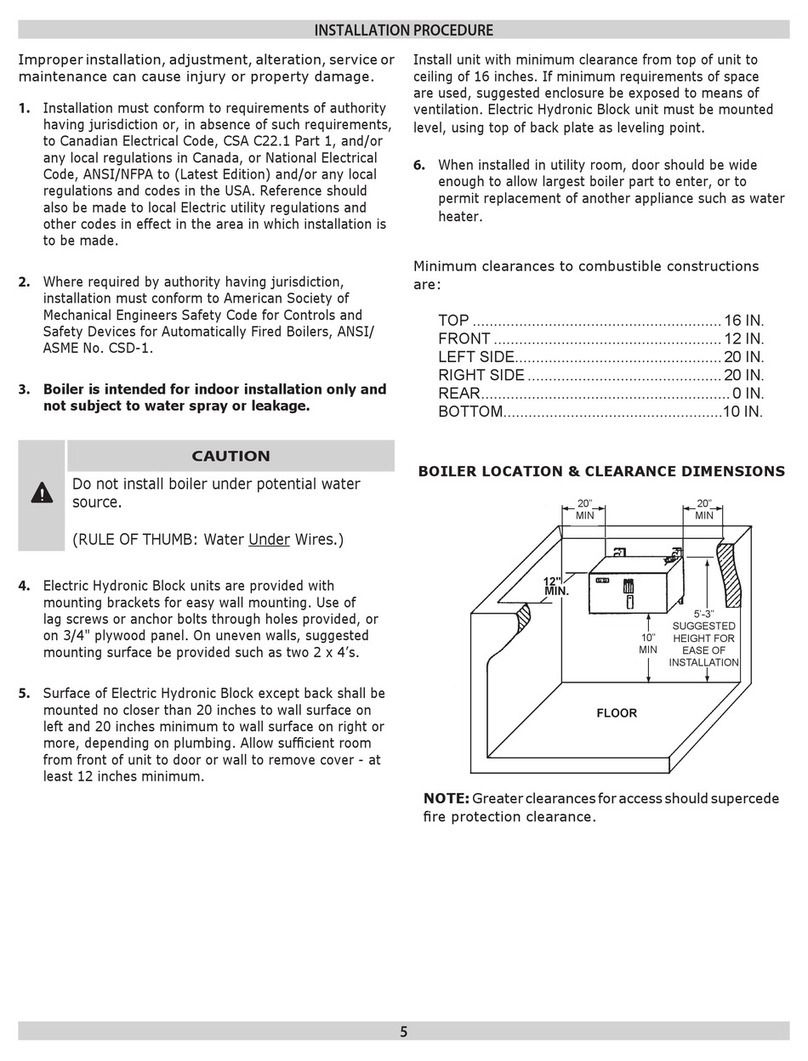
INSTALLATION PROCEDURE
Improperinstallation,adjustment,alteration,service
or maintenance can cause injury or property
damage.
1. Theinstallationmustconformtotherequirements
of the authority having jurisdiction or, in absence
of such requirements, to the latest revision of
the Canadian Electrical Code, CSA C22.1 Part
1, and/or any local regulations in Canada, or the
National Electrical Code, ANSI/NFPA to (Latest
Edition) and/or any local regulations and codes
in the USA. Reference should also be made to
local Electric utility regulations and other codes
in effect in the area in which the installation is to
be made.
2. Whererequiredbytheauthorityhavingjurisdiction,
theinstallationmustconformtoAmericanSociety
ofMechanicalEngineersSafetyCodeforControls
andSafetyDevicesforAutomaticallyFiredBoilers,
ANSI/ASME No. CSD-1.
3. The Boiler is intended for indoor installation
only and not subject to water spray or
leakage.
CAUTION
Do not install boiler UNDER potential water
source.
(RULE OF THUMB: Water Under Wires.)
4. Electric Hydronic Block units are provided with
mounting brackets for easy wall mounting. The
unit may be mounted directly on the wall by the
use of lag screws or anchor bolts through holes
provided,oron a 3/4"plywood panel. Onuneven
walls, it is suggested that a mounting surface be
provided such as two 2 x 4’s.
5. AnysurfaceoftheElectricHydronicBlockexcept
the back shall be mounted no closer than 20
inches to the wall surface on the left and 20
inches minimum to wall surface on the right or
more, depending on plumbing. Allow sufcient
room from the front of the unit to a door or wall
to remove cover - at least 12 inches minimum.
Install unit with a minimum clearance from
top of unit to ceiling of 16 inches. If minimum
requirements of space are used, it is suggested
thatthe enclosure beexposed tosome meansof
ventilation.The electric HydronicBlock unit must
be mounted level, using the top of the back plate
as a leveling point.
6. When installed in utility room, the door should
be wide enough to allow the largest boiler part
to enter, or to permit replacement of another
appliance such as a water heater.
Minimum clearances to combustible constructions
are:
TOP ...................................................16 IN.
FRONT..............................................12 IN.
LEFT SIDE.........................................20 IN.
RIGHT SIDE......................................20 IN.
REAR...................................................0 IN.
BOILER LOCATION & CLEARANCE DIMENSIONS
NOTE: Greater clearances for access should
supercede re protection clearance.

6
DESIGN OF WATER
CIRCULATING SYSTEM
System should be designed as primary/secondary
piping and to operate with a maximum output tem-
perature of 180º F or lower and a temperature rise
across the unit of 20º F or lower. Refer to tables
below and Figures 2 & 3.
NOTE:Topreventcondensation,thereturnwater
temperature must be higher than the room tem-
perature in which the boiler is installed.
at the bottom of the unit. Reverse ow will result
inanoisyoperationandcauseveryearlyelement
failure. The drain cock is to be located at the
lowest point of piping.
5. The outlet or supply pipe line to the radiation
is located at the top of unit. A combination
temperaturepressure(altitude)gaugeisprovided
witheachunitandshouldbeinstalledclosetothe
boileroutlet. It is important thatthe gauge sensor
be completely immersed in the owing water so as
toassurecorrecttemperaturereadings.Manualor
automatic water make up supply may be located
inthis area below.Thecirculator pumpshould be
installed on the supply side (pumping away).
6. Gate valves should be installed at the locations
showninFigures2&3,so thatanyboilerservicing
requiringremovalofwatercanbedonequicklyand
easily.Notillustratedbutalsohighlyrecommended
is the installation of air vents at the high points
ofthehydonic system.Thesedevices willreduce
initialstartuptimeandhelpavoidelementburnout
during the entire life of the heating system.
7. A pressure relief valve is supplied with each
Electric Hydronic Block and should be installed
at the location and discharge direction shown in
Figure 1, using pipe nipple and elbow supplied.
Piping should be added so that any water that
may be discharged will not damage the boiler or
other system components.
PLUMBING AND
ACCESSORY
INSTALLATION
FIGURE 1
8.ForfurtherpipinginformationrefertoTheHydronics
Institute (I=B=R) manual 200 (Installation Guide for
Residential Hydronics).
“AT” Series - 2 Element Boiler
KW Capacity Minimum Flow Rate (GPM)*
6 2.0
8 2.7
10 3.4
12 4.1
“AT” Series - 4 Element Boiler
KW Capacity Minimum Flow Rate (GPM)*
12 4.1
16 5.5
20 6.8
24 8.2
* Flow rate based on 20°ΔT
CONNECTING SUPPLY
AND RETURN PIPING
1. Maintain a minimum clearance of one inch to hot
water pipes.
2. Hot water boilers installed above radiation level
must be provided with a low water cutoff device
either as part of the boiler or at the time of boiler
installation.
NOTE: In some states a low water cutoff device
(LWCO) may be required. Check your local codes.
3. When a boiler is connected to a heating system
that utilizes multiple zoned circulators, each
circulator must be supplied with a ow control
valve to prevent gravity circulation.
NOTE: Reduced pressure back ow provender
mustbepresentunderprovisionsrequiredbythe
Environmental Protection Agency, (EPA).
4.Suggestedplumbingarrangementsareillustrated
inFigures2&3.Theinletorreturnpipeislocated

7
PRIMARY/SECONDARY PIPING FOR
MULTIPLE ZONING WITH ZONE VALVES
FIGURE 3
PRIMARY/SECONDARY PIPING FOR
MULTIPLE ZONING WITH CIRCULATORS
FIGURE 2
PRIMARY/SECONDARY PIPING

8
CONNECTING ELECTRICAL POWER SUPPLY
! !
WIRING THE BOILER
WARNING
DO NOT USE ALUMINUM WIRE!!
Argo Electric Hydronic Boilers are pre-wired for
use with 240-volt, 3 wire, single-phase, 50/60-hertz
power. RefertoTable 1Bon page 4forthe reduction
in boiler capacity when the line voltage is less than
240 volts.
An opening is provided in the jacket bottom panel
for the eld wiring, refer to the rating chart for
recommended wire sizes.
Allelectricalwiringmustbedoneinaccordancewith
theCanadianElectricalCode,CSAC22.1Part1,and
/or any local regulations and codes in Canada, or
the National Electrical code,ANSI/NFPA 70 (Latest
edition) and/or any local regulations and codes in
USA. Verify the nameplate rating and check the
related codes to properly size conductors, switches
and over current protection. Several openings are
provided on the bottom of the cabinet for different
voltage connections. For wire connections refer to
the wiring diagram on the inside of the boiler front
cover. Do not use aluminum wire!!
Allcircuitbreakersordisconnectsaheadoftheboiler
must be OFF. If boiler contains integral breakers
(depending on option), it is recommended that they
arealsoturnedoffatthistime.Removetheboilerfront
cover by removing 4 screws from the top and sides.
When a boiler is used in a zoned system, the zone
valves must be powered from an independent
source and have electrically isolated end switches
or isolating relays wired in parallel to the boiler
thermostat terminals. Do not attempt to power
zone valves from the transformer in the boiler
control system!!
WIRING ON CONTROL
PUMP: Connect only 120 Vac 1/6 HP (maximum)
pumptoterminalsC1(L)andC2(N)onthecontroller.
Strip wire ends before inserting into terminal block.
Tighten terminal screws. Do not use a pump
requiring greater than 5 amps!!
THERMOSTAT: Connect thermostat or zone valve
end switch to terminals TT and TT (Figure 4). Do
not apply an external power source to these
terminals!! Strip wire ends before inserting into
terminal block. Tighten terminal screw clamps.
LIMIT CONTROL OPERATION
1. When the boiler water temperature exceeds the
high limit setting on the aquastat, all heating
elementcontrolrelaysareinstantlyde-energized.
Circulator continues to operate until call for heat
ends. When water temperature drops below
aquastatre-setdifferential,heatingelementpower
relays close as per time delay sequence.
2. MAIN POWER SUPPLY: Depending on model
designation, the electric Hydronic Block may be
energized by the following alternating current
service entrances: 240 volt single phase 50 or
60 cycle 3 wire. The wire size required may be
selectedfromTable1.Thesizeslistedforvarious
capacity units include total amperes necessary
to operate elements, circulator and zone valves
where used. Wire sizes specied conform to the
Canadian Electrical Code (Canada) or National
Electric Code (USA) and include derating for
FIGURE 4
FIGURE 5

9
ampacityandtemperature.Usecopperwireonly
withinsulationratedfor75 °C.Checkstateand
local requirements.
NOTE: Read the data name plate before
connecting unit so that you will become
familiar with the specications. All electrical
connections to the unit are provided and
located for ease of proper installation.
IMPORTANT: Useonlycopperwireofproper
size and make sure all terminations are very
tight. Do not use aluminum wire!!
3. CIRCULATOR POWER SUPPLY: Terminals
identied as C1(L) and C2(N) at the bottom
of the control panel (Figure 5) may be used to
supplyonecirculatorpumppower.Thecirculator
motor shall not be larger than 1/6 horsepower
witha maximum5.0amprating.Wiringfromthe
controlpaneltothepumpshouldhaveinsulation
ratedat75°C.Circuitprotectionisprovidedbya
15 amp breaker or fuse (depending on option)
on the control board.
NOTE: If the circulator pump is larger
than the maximum size listed above, then
a separate circulator pump relay must be
provided with separate overload protection.
Where more than one circulator is used for
zoning, it must be installed and protected
according to approved electrical codes.
CONTROL INFORMATION
CONTROL BOARD SPECIFICATIONS:
Dimensions: 5-7/8"(W) x 9-3/8" (L) x 1-5/8" (H)
Operating Control Outlet Water Tempera-
ture:
90°F - 180°F (adjustable)
High Limit Control Outlet Water Tempera-
ture:
200°F (xed)
Control Input Voltage: 120V ac
Control Output Voltage: 120V ac, 5Amax. (cir-
culator terminal)
POWER OUTPUT: One 120V ac pump output is
switched by an onboard circulator relay. The load
current is limited and must not exceed 5A.
CONTROL BOARD POWER CONSUMPTION:
0.8A max.
LED DISPLAY LIGHTS (Figure 6):Atotal of 8 LED
indicator lights display the following information:
(1) T-T (Green): LED is lit when thermostat is
calling for heat.
(2) Fault (Red): LED is lit/ashes when there is
an operating error/safety fault.
(3) Safety Switch (Green): LED is lit when there
are no safety faults.
(4) Circ (Green): LED is lit when circulator termi-
nals are energized.
(5) Heating Element#1 (Green): LED is lit when
element#1 is energized.
(6) Heating Element#2 (Green): LED is lit when
element#2 is energized.
(7) Heating Element#3 (Green): LED is lit when
element #3 is energized.
(8) Heating Element#4 (Green): LED is lit when
element#4 is energized.
FIGURE 6
SIGNAL/CONTROL INPUTS:
TT: Thermostatorzonevalveend switch, switch-
ing input, closed is activation.
HL: High limit temperature sensors (factory in-
stalled), normally closed.
LWC: Low water cutoff (optional) end switch,
normally closed (factory installed jumper).
FLOW:Flowswitch(optional)endswitch,normally
closed (factory installed jumper).

10
TEMPERATURE CONTROL RANGES:
Temperature: Degrees Fahrenheit
Operating Temperature Range:
90°F - 180°F
(Factory Setting: 180°F)
Operating Temperature Differential Range:
+/- 4°F - +/- 20°F
(Factory Setting: 12°F)
Fixed High Limit Temperature: 200°F
OPERATING TEMPERATURE AND DIFFEREN-
TIALADJUSTMENTS: Internaltemperaturepoten-
tiometer on the control.
CONTROL OPERATION: When the control switch
is in the "On" position and all safety end switches
are closed, the "Safety Switch" LED is lit. Once in
operating mode, the control uses the well-mounted
(RTD) sensor to continuously monitor the boiler
water temperature.
When the thermostat calls for heat ("TT" LED is lit),
the control will energize the circulator ("Circ" LED
is lit) for 30 seconds to establish ow. Next the con-
trol will measure water temperature and differential
setting, perform a check for an "open" or "shorted"
RTD sensor, check that all safety end switches are
"closed," and check for stuck or welded element
relay contacts. Next, the control will energize only
one element ("Element" LED is lit) and monitor
water temperature for 60 seconds. The control will
energize additional elements at 30 second intervals
to bring the system up to set point temperature in
5 minutes.
Once the system reaches the set point temperature
andthereis stillacall forheat,the controlwill modu-
late the number of elements on and off in order to
maintain the set point temperature. The required
number of elements which are energized is deter-
mined by heating demand, which is the difference
between actual boiler water temperature and set
point temperature.
After the call for heat has been satised, the elements
will be de-energized ("Element" LEDs turn off) by
the control and the circulator will continue to be
energized for 3 minutes to purge the boiler.After
3 minutes the control will de-energize the circulator
("Circ" LED turns off).
Ifatanytimeduringthestart-upoftheboilerorduring
operation a safety end switch opens its respective
contact, the control de-energizes all elements,
continues to energize the circulator, and ashes a
visible fault code ("Fault" LED ashes) along with
an audible fault code. (See fault codes (below)) The
control has a built-in reset function.
TEMPERATURE SETTING: The water "Set
point" temperature adjustment dial on the control
should always be set at the designed boiler water
temperature.
CONTROL MOUNTING: The control is mounted
using 1/2" tall plastic standoffs. The indicator LEDs
are visible through a clear polycarbonate viewing
window on front cover of the boiler.
PROTECTION FROM LIQUIDS: The control and
other components located within the control panel
are sensitive to water and other liquids. Measures
must be taken to fully protect components on panel
from contact with liquids.
FAULT CODES (VISUAL/AUDIBLE):
RTD SENSOR:
To conrm that the RTD sensor is functioning prop-
erly, follow the steps below.
1. Remove both RTD leads from the terminal block
on the boiler control board.
2. Use a multimeter to take an ohm reading across
the RTD leads. A properly functioning RTD will
produce a reading of approximately 1000 ohms
at 70° F. A faulty RTD will read either 0 or 1 on
your multimeter.
3. Replace RTD if necessary.
Number of
Flashes/Pulses Description
1 Safety switch fault
2 Stuck/welded element relay contact
3 RTD short
4 RTD open
CONTROL INFORMATION continued

11
HEATING ELEMENTS
ENERGIZED
(ACTIVATION DES
ÉLÉMENTS DE
CHAUFFAGE)
SOURCE POWER, 240V/60HZ/1PH 3-WIRE, BY OTHERS
(SOURCE DU COURANT, 240V/60HZ/1PH 3-FILS, OU AUTRES)
EQUIPMENT GROUNDING LUG
(TENON DE PRISE Á LA TERRE DE Ľ APPAREIL)
N
NEUTRALBLOCK
(BLOC NEUTRE)
WHT (BLANC)
WHT/BLK (BLANC/NOIR)
BLK (NOIR)
NOT USED
(NON UTILISÉ)
NOT USED
(NON UTILISÉ)
L
OFF
(FERMÉ)
120VAC
CIRC
C1 C2
NL
CIRC
N
120VAC
INPUT
(ENTRÉE)
WHT (BLANC)
NOT USED
(NON UTILISÉ)
NOT USED
(NON UTILISÉ)
CONTROL
(COMMANDE)
RED (ROUGE)
TRANSFORMER
(TRANSFORMATEUR) ON
(OUVERT)
ARGO "AT" ELECTRIC BOILER
SCHEMATIC WIRING DIAGRAM
2 ELEMENT BOILER,
WITH POWER BLOCK
WHT/BLK (BLANC/NOIR)
WHT (BLANC)
WHT/BLK (BLANC/NOIR)
WHT (BLANC)
L1
H2
L2
L2
H1
H2
RED (ROUGE)
LWC
FLOW
FLOW
LWC
RED (ROUGE)
HL
HL
TT
TT
FAULT
(DÉFAILLANCE)
4
13
2
SAFETY SWITCHES
(INTERRUPTEURS DE SÉCURITÉ)
T-T
WHT/BLK (BLANC/NOIR)
L1
H1
WHT (BLANC)
RTD
SETPOINT
(RÉGLAGE) DIFFERENTIAL
(DIFFÉRENTIEL)
THERMOSTAT, BY OTHERS
(THERMOSTAT, OU AUTRES)
L1
POWER BLOCK
(BLOC DE PUISSANCE)
L2
FUSE BLOCK
(BLOC DE FUSIBLE)
WIRE LEGEND / (LÉGENDE DES FILS)
- DRY CONTACT WIRING (POSE DES CÂBLES DE CONTACT SEC)
- 120 VOLT WIRING (POSE DES CÂBLES 120 VOLT)
- 240 VOLT WIRING (POSE DES CÂBLES 240 VOLT)
- 120 VOLT FIELD WIRING (POSE DES CÂBLES 120 VOLTSUR EN CHANTIER)
- 240 VOLT FIELD WIRING (POSE DES CÂBLES 240 VOLTEN CHANTIER)
- DRY CONTACT FIELD WIRING (POSE DES CÂBLES DE CONTACT SEC EN CHANTIER)
(DIAGRAMME SCHÉMATIQUE DU CÂBLAGE
D'UNE CHAUDIÈRE À 2 ÉLÉMENTS)
HIGH LIMIT SAFETY SWITCH, AUTO RESET
(INTERRUPTEUR DE SÉCURITÉ DE LIMITE SUPÉRIEURE,
REMISE EN MARCHE AUTOMATIQUE)
HIGH LIMIT SAFETY SWITCH, AUTO RESET
(INTERRUPTEUR DE SÉCURITÉ DE LIMITE SUPÉRIEURE,
REMISE EN MARCHE AUTOMATIQUE)
OPTIONAL FLOW SWITCH, BY OTHERS
(INTERRUPTEUR DE DÉBIT - FACULTATIF, OU AUTRES)
SOURCE POWER, 120V/60HZ/1PH , BY OTHERS
(SOURCE DU COURANT, 120V/60HZ/1PH, OU AUTRES)
OPTIONAL LWCO, BY OTHERS
(ISPOSITIF D'ARRET EN CAS FAIBLE NIVEAU D'EAU -
FACULTATIF - OU AUTRES)
RTD WATER TEMPERATURE SENSOR
(CAPTEUR DE LA TEMPÉRATURE DE ĽEAU RTD)
CIRCULATOR PUMP, BY OTHERS
(POMPE DE ĽACCELERTEUR, OU AUTRES)
CIRCULATOR RELAY
(RELAIS DU
ĽACCELERTEUR)
FACTORY INSTALLED JUMPERS
(CALVALIERS INSTALLÉES Á ĽUSINE)
ARGO ELECTRONIC BOILER CONTROL
(COMMANDE ÉLECTRONIQUE DE LA CHAUDIÈRE ARGO)
ELEMENT #1
(ÉLÉMENT No1) ELEMENT #1 RELAYS
(RELAIS DE ĽÉLÉMENT No1)
ELEMENT #2
(ÉLÉMENT No2) ELEMENT #2 RELAYS
(RELAIS DE ĽÉLÉMENT No2)
,!"%,02).4%$/.7()4%02%3352%3%.3)4)6%
-!4%2)!,7)4(",!#+4%84
./4%
WIRING DIAGRAMS
FIGURE 7A

12
- DRY CONTACT FIELD WIRING (POSE DES CÂBLES DE CONTACT SEC EN CHANTIER)
LOAD CENTER
(CENTRE DE CHARGE)
ON
(OUVERT)
TRANSFORMER
(TRANSFORMATEUR)
NEUTRALBLOCK
(BLOC NEUTRE)
EQUIPMENT GROUNDING LUG
(TENON DE PRISE Á LA TERRE DE Ľ APPAREIL)
WHT (BLANC)
WHT/BLK (BLANC/NOIR)
CIRCULATOR PUMP, BY OTHERS
(POMPE DE ĽACCELERTEUR, OU AUTRES)
N
SOURCE POWER, 240V/60HZ/1PH 3-WIRE, BY OTHERS
(SOURCE DU COURANT, 240V/60HZ/1PH 3-FILS, OU AUTRES)
120VAC
INPUT
(ENTRÉE)
N
CIRC
NOT USED
(NON UTILISÉ)
CIRCULATOR RELAY
(RELAIS DU
ĽACCELERTEUR)
L N
C2
C1
120VAC
CIRC
NOT USED
(NON UTILISÉ)
OFF
(FERMÉ)
BLK (NOIR)
21
LL1 L2
ARGO "AT" ELECTRIC BOILER
SCHEMATIC WIRING DIAGRAM
2 ELEMENT BOILER,
WITH BREAKERS
(DIAGRAMME SCHÉMATIQUE DU CÂBLAGE
D'UNE CHAUDIÈRE À 2 ÉLÉMENTS)
- 240 VOLTFIELD WIRING (POSE DES CÂBLES 240 VOLT EN CHANTIER)
- 120 VOLTFIELD WIRING (POSE DES CÂBLES 120 VOLT SUR EN CHANTIER)
- 240 VOLTWIRING (POSE DES CÂBLES 240 VOLT)
- 120 VOLTWIRING (POSE DES CÂBLES 120 VOLT)
OPTIONAL LWCO, BY OTHERS
(ISPOSITIF D'ARRET EN CAS FAIBLE NIVEAU
D'EAU - FACULTATIF - OU AUTRES)
SOURCE POWER, 120V/60HZ/1PH , BY OTHERS
(SOURCE DU COURANT, 120V/60HZ/1PH, OU AUTRES)
OPTIONAL FLOW SWITCH, BY OTHERS
(INTERRUPTEUR DE DÉBIT - FACULTATIF, OU AUTRES)
THERMOSTAT, BY OTHERS
(THERMOSTAT, OU AUTRES)
ELEMENT #1
(ÉLÉMENT No1) ELEMENT #1 RELAYS
(RELAIS DE ĽÉLÉMENT No1)
H2
HEATING ELEMENTS
ENERGIZED
(ACTIVATION DES
ÉLÉMENTS DE
CHAUFFAGE)
ARGO ELECTRONIC BOILER CONTROL
(COMMANDE ÉLECTRONIQUE DE LA CHAUDIÈRE ARGO)
NOT USED
(NON UTILISÉ)
NOT USED
(NON UTILISÉ)
RED (ROUGE)
CONTROL
(COMMANDE)
T-T
SAFETY SWITCHES
(INTERRUPTEURS DE SÉCURITÉ)
2
3
1
4
FAULT
(DÉFAILLANCE)
H1 L2
L2
ELEMENT #2
(ÉLÉMENT No2)
H2
ELEMENT #2 RELAYS
(RELAIS DE ĽÉLÉMENT No2)
L1
TT
TT
HL
HL RED (ROUGE)
LWC
FLOW
FLOW
FACTORY INSTALLED JUMPERS
(CALVALIERS INSTALLÉES Á ĽUSINE)
LWC
DIFFERENTIAL
(DIFFÉRENTIEL)
SETPOINT
(RÉGLAGE)
H1 L1 RTD
RTD WATER TEMPERATURE SENSOR
(CAPTEUR DE LA TEMPÉRATURE DE ĽEAU RTD)
WHT (BLANC)
- DRY CONTACT WIRING (POSE DES CÂBLES DE CONTACT SEC)
RED (ROUGE)
HIGH LIMIT SAFETY SWITCH, AUTO RESET
(INTERRUPTEUR DE SÉCURITÉ DE LIMITE SUPÉRIEURE,
REMISE EN MARCHE AUTOMATIQUE)
WHT (BLANC)
WHT/BLK (BLANC/NOIR)
WHT (BLANC)
WHT (BLANC)
WHT/BLK (BLANC/NOIR)
WHT (BLANC)
HIGH LIMIT SAFETY SWITCH, AUTO RESET
(INTERRUPTEUR DE SÉCURITÉ DE LIMITE SUPÉRIEURE,
REMISE EN MARCHE AUTOMATIQUE)
WIRE LEGEND / (LÉGENDE DES FILS)
WIRING DIAGRAMS
FIGURE 7B

13
WHT/BLK (BLANC/NOIR)
NEUTRALBLOCK
(BLOC NEUTRE)
WHT/BLK (BLANC/NOIR)
WHT (BLANC)
WHT (BLANC)
WHT (BLANC)
WHT/BLK (BLANC/NOIR)
OFF
(FERMÉ)
ELEMENT #4
(ÉLÉMENT No4)
WHT (BLANC) L2
H4
ELEMENT #4 RELAYS
(RELAIS DE ĽÉLÉMENT No4)
120VAC
INPUT
(ENTRÉE)
NL
C1
L
120VAC
CIRC
C2
N
CIRC
H4 L1
L2
H3
WHT/BLK (BLANC/NOIR)
WHT (BLANC) CONTROL
(COMMANDE)
ON
(OUVERT)
TRANSFORMER
(TRANSFORMATEUR)
HL
T-T
HEATING ELEMENTS
ENERGIZED
(ACTIVATION DES
ÉLÉMENTS DE
CHAUFFAGE)
H2
WHT/BLK (BLANC/NOIR)
L1
H3
ELEMENT #3
(ÉLÉMENT No3) ELEMENT #3 RELAYS
(RELAIS DE ĽÉLÉMENT No3)
WHT (BLANC)
13
L2
2
L1
H2
ELEMENT #2
(ÉLÉMENT No2)
WHT/BLK (BLANC/NOIR)
ELEMENT #2 RELAYS
(RELAIS DE ĽÉLÉMENT No2)
LWC
FLOW
FLOW
LWC
4
FAULT
(DÉFAILLANCE)
SETPOINT
(RÉGLAGE)
WHT/BLK (BLANC/NOIR)
L2
H1
L1
H1
ELEMENT #1
(ÉLÉMENT No1)
WHT (BLANC)
ELEMENT #1 RELAYS
(RELAIS DE ĽÉLÉMENT No1)
RTD
HL
TT
TT
DIFFERENTIAL
(DIFFÉRENTIEL)
WHT (NOIR)
ARGO "AT" ELECTRIC BOILER
SCHEMATIC WIRING DIAGRAM
4 ELEMENT BOILER,
WITH POWER BLOCK
(DIAGRAMME SCHÉMATIQUE DE LAPOSE DES
FILS D'UNE CHAUDIÈRE À 4 ÉLÉMENTS)
SOURCE POWER, 240V/60HZ/1PH 3-WIRE, BY OTHERS
(SOURCE DU COURANT, 240V/60HZ/1PH 3-FILS, OU AUTRES)
N
RED (ROUGE)
RED (ROUGE)
RED (ROUGE)
THERMOSTAT, BY OTHERS
(THERMOSTAT, OU AUTRES)
WHT/BLK (BLANC/NOIR)
WHT (BLANC)
FUSE BLOCK
(BLOC DE FUSIBLE)
BLK (NOIR)
L2L1
POWER BLOCK
(BLOC DE PUISSANCE)
- 240 VOLT FIELD WIRING (POSE DES CÂBLES 240 VOLT EN CHANTIER)
EN CHANTIER)
- 120 VOLT WIRING (POSE DES CÂBLES 120 VOLT)
- 240 VOLT WIRING (POSE DES CÂBLES 240 VOLT)
- 120 VOLT FIELD WIRING (POSE DES CÂBLES 120 VOLT SUR EN CHANTIER)
- DRY CONTACT WIRING (POSE DES CÂBLES DE CONTACT SEC)
- DRY CONTACT FIELD WIRING (POSE DES CÂBLES DE CONTACT SEC
WIRE LEGEND / (LÉGENDE DES FILS)
OPTIONAL FLOW SWITCH, BY OTHERS
(INTERRUPTEUR DE DÉBIT - FACULTATIF, OU AUTRES)
OPTIONAL LWCO, BY OTHERS
(ISPOSITIF D'ARRET EN CAS FAIBLE NIVEAU D'EAU -
FACULTATIF - OU AUTRES)
SOURCE POWER, 120V/60HZ/1PH , BY OTHERS
(SOURCE DU COURANT, 120V/60HZ/1PH, OU AUTRES)
EQUIPMENT GROUNDING LUG
(TENON DE PRISE Á LA TERRE DE Ľ APPAREIL)
RTD WATER TEMPERATURE SENSOR
(CAPTEUR DE LA TEMPÉRATURE DE ĽEAU RTD)
HIGH LIMIT SAFETY SWITCH, AUTO RESET
(INTERRUPTEUR DE SÉCURITÉ DE LIMITE SUPÉRIEURE,
REMISE EN MARCHE AUTOMATIQUE)
HIGH LIMIT SAFETY SWITCH, AUTO RESET
(INTERRUPTEUR DE SÉCURITÉ DE LIMITE SUPÉRIEURE,
REMISE EN MARCHE AUTOMATIQUE)
FACTORY INSTALLED JUMPERS
(CALVALIERS INSTALLÉES Á ĽUSINE)
ARGO ELECTRONIC BOILER CONTROL
(COMMANDE ÉLECTRONIQUE DE LA CHAUDIÈRE ARGO)
SAFETY SWITCHES
(INTERRUPTEURS DE SÉCURITÉ)
CIRCULATOR RELAY
(RELAIS DU
ĽACCELERTEUR)
CIRCULATOR PUMP, BY OTHERS
(POMPE DE ĽACCELERTEUR, OU AUTRES)
WIRING DIAGRAMS
FIGURE 8A

14
SOURCE POWER, 240V/60HZ/1PH 3-WIRE, BY OTHERS
(SOURCE DU COURANT, 240V/60HZ/1PH 3-FILS, OU AUTRES)
NEUTRALBLOCK
(BLOC NEUTRE)
WHT/BLK (BLANC/NOIR)
WHT (BLANC)
N
WHT (BLANC)
WHT/BLK (BLANC/NOIR)
WHT (BLANC)
WHT (BLANC)
ELEMENT #4 RELAYS
(RELAIS DE ĽÉLÉMENT No4)
WHT/BLK (BLANC/NOIR)
ELEMENT #4
(ÉLÉMENT No4)
OFF
(FERMÉ)
N
C2
120VAC
CIRC
L
C1
H4 L2
L
N
120VAC
INPUT
(ENTRÉE)
TRANSFORMER
(TRANSFORMATEUR)
H3 L2
L1
H4 CIRC
ON
(OUVERT)
CONTROL
(COMMANDE)
BLK (NOIR)
ARGO "AT" ELECTRIC BOILER
SCHEMATIC WIRING DIAGRAM
4 ELEMENT BOILER,
WITH BREAKERS
L2
L1
ARGO LOAD CENTER
(CENTRE DE CHARGE ARGO)
THERMOSTAT, BY OTHERS
(THERMOSTAT, OU AUTRES)
RED (ROUGE)
T-T HL
ELEMENT #2 RELAYS
(RELAIS DE ĽÉLÉMENT No2)
ELEMENT #3 RELAYS
(RELAIS DE ĽÉLÉMENT No3)
WHT/BLK (BLANC/NOIR)
ELEMENT #3
(ÉLÉMENT No3)
ELEMENT #2
(ÉLÉMENT No2)
H2
HEATING ELEMENTS
ENERGIZED
(ACTIVATION DES
ÉLÉMENTS DE
CHAUFFAGE)
H3 L1
RED (ROUGE)
H2 L1
FAULT
(DÉFAILLANCE)
4
2
L2
3
1
LWC
FLOW
FLOW
LWC
ELEMENT #1 RELAYS
(RELAIS DE ĽÉLÉMENT No1)
WHT (BLANC)
ELEMENT #1
(ÉLÉMENT No1)
DIFFERENTIAL
(DIFFÉRENTIEL)
H1 L1
SETPOINT
(RÉGLAGE)
H1
L2
TT
TT
HL
RTD
WHT (NOIR)
WHT/BLK (BLANC/NOIR) WHT (BLANC)
WHT/BLK (BLANC/NOIR)
WHT (BLANC)
WHT/BLK (BLANC/NOIR)
WHT (BLANC)
RED (ROUGE)
WIRE LEGEND / (LÉGENDE DES FILS)
- DRY CONTACT WIRING (POSE DES CÂBLES DE CONTACT SEC)
- 120 VOLT WIRING (POSE DES CÂBLES 120 VOLT)
- 240 VOLT WIRING (POSE DES CÂBLES 240 VOLT)
- 120 VOLT FIELD WIRING (POSE DES CÂBLES 120 VOLT SUR EN CHANTIER)
- 240 VOLT FIELD WIRING (POSE DES CÂBLES 240 VOLT EN CHANTIER)
(DIAGRAMME SCHÉMATIQUE DU CÂBLAGE
D'UNE CHAUDIÈRE À 4 ÉLÉMENTS)
- DRY CONTACT FIELD WIRING (POSE DES CÂBLES DE CONTACT SEC
EN CHANTIER)
EQUIPMENT GROUNDING LUG
(TENON DE PRISE Á LA TERRE DE Ľ APPAREIL)
OPTIONAL FLOW SWITCH, BY OTHERS
(INTERRUPTEUR DE DÉBIT - FACULTATIF, OU AUTRES)
SOURCE POWER, 120V/60HZ/1PH , BY OTHERS
(SOURCE DU COURANT, 120V/60HZ/1PH, OU AUTRES)
OPTIONAL LWCO, BY OTHERS
(ISPOSITIF D'ARRET EN CAS FAIBLE NIVEAU D'EAU -
FACULTATIF - OU AUTRES)
HIGH LIMIT SAFETY SWITCH, AUTO RESET
(INTERRUPTEUR DE SÉCURITÉ DE LIMITE SUPÉRIEURE,
REMISE EN MARCHE AUTOMATIQUE)
HIGH LIMIT SAFETY SWITCH, AUTO RESET
(INTERRUPTEUR DE SÉCURITÉ DE LIMITE
SUPÉRIEURE, REMISE EN MARCHE AUTOMATIQUE)
FACTORY INSTALLED JUMPERS
(CALVALIERS INSTALLÉES Á ĽUSINE)
RTD WATER TEMPERATURE SENSOR
(CAPTEUR DE LA TEMPÉRATURE DE ĽEAU RTD)
CIRCULATOR PUMP, BY OTHERS
(POMPE DE ĽACCELERTEUR, OU AUTRES)
CIRCULATOR RELAY
(RELAIS DU
ĽACCELERTEUR)
ARGO ELECTRONIC BOILER CONTROL
(COMMANDE ÉLECTRONIQUE DE LA CHAUDIÈRE ARGO)
SAFETY SWITCHES
(INTERRUPTEURS DE SÉCURITÉ)
WIRING DIAGRAMS
FIGURE 8B

15
THERMOSTAT INSTALLATION
1. Thermostat should be installed on an inside wall
about four feet above the oor.
2. NEVER install a thermostat on an outside wall.
3.Donotinstalla thermostatwhereitwillbe affected
by sunlight, drafts, televisions, lighting xtures, hot
or cold pipes, replaces, or chimneys.
NOTE: YournewArgoATBoiler
will work well with all standard
and most programmable set-
back thermostats. In the event
the programmable thermostat
you use causes the boiler con-
trol T-T LED to icker on and off
when there is no call for heat,
your thermostat will require
an external 24V power supply
(transformer)andisolationrelay
or an Argo "AR822" control.
! !
! !
It is suggested that a qualied service agency be
employedtomakeanannualinspectionoftheboiler
and the heating system. They are experienced in
making the inspection outlined below. In the event
repairs or corrections are necessary they can make
the proper changes for safe operation of the boiler.
CAUTION
Label all wires prior to disconnection when
servicing controls. Wiring errors can cause
improper and dangerous operation. Verify
proper operation after service.
After all procedures have been carefully followed
and completed, the hydronic block is now ready to
be put into service.
1. Check hydronic block circuit breaker or switch at
theserviceentranceand,dependingontheoption,
the hydronic block circuit breakers within the unit
to assure that they are in the "Off" position.
WARNING
Only propylene glycol can be used in heating
systemtopreventfreezing.Recommendationis
amaximum40%orlesspropyleneglycolmixture
to ensure proper operation of electric boiler.
! !
2.Filltheheatingsystemwithwateruntilthepressure
reaches 10-15 PSI. Check for leaks, repair if
necessary, and purge all air from system.
CAUTION
Failure to vent and keep air out of the heating
system will result in damage to heating
elements in the hydronic block. Damage of
thistypeisnotcoveredbythemanufacturer's
warranty.
3. Set the boiler operating temperature to designed
heating water temperature by adjusting the
potentiometer dial located on the top center of the
controller (Figure 4). Adjust arrow on temperature
adjustment dial to the water temperature required.
NOTE: This boiler is also equipped with a high-
limit temperature device set at 200°F as a safety
limit control. The high limit temperature device
has an automatic reset function and will reset
at 170°F.
4. Turn on the hydronic block circuit breaker at the
service entrance and/or disconnect switch and,
dependingontheoption,the15ampcircuitbreaker
on the hydronic block.
5.Setonethermostataboveroomtemperature.The
circulator pump will now operate.
4. Instructions for nal adjustment of the thermo-
stat (adjusting heating anticipator, calibration,
etc.) are packaged with the thermostat. Recom-
mended setting for the heating anticipator is
0.1 amps.
THERMOSTAT INSTALLATION
STARTUP AND SEASONAL MAINTENANCE

16
8. When the thermostat calls for heat, the circulator
will be energized and the indicator LED will light
up. Next, the heating elements are energized
along with the element indicator LEDs. Once the
boilerwatertemperaturereachesthesetpointon
thetemperatureadjustmentdial,thecontrollerwill
regulate the boiler by staging its elements. The
number of elements which stay on is based on
theheatingdemandandthesetpointoftheboiler
watertemperature.Afterallroomthermostatsare
satised with the heat, the controller de-energizes
theelementsoneafteranother,andthenswitches
the pump off after 3 minutes.
TROUBLESHOOTING
2.Closegatevalvesnearinletandoutletofhydronic
block.
3. Close feed line valve if using automatic ll.
4. Open drain valve and allow water to drain from
theboiler.Manualoperationofthe reliefvalvewill
assist drainage by allowing air to enter.
5. Remove cabinet cover and disconnect the two
wires attached to the effected heating element.
6. Remove the four bolts that secure the heating
element to thecastingandprytheelementloose.
Take note of the markings on the element ange
to assure proper reinstallation.
7. After the element has been removed, carefully
clean any remaining gasket material from the
castingsurface.Takecarenotto scratchorscore
this surface.
8. Install new gasket and heating element
while assuring that the element is correctly
positioned.
9. Close relief valve. Open feed line valve and
checkforleaks.Opengatevalves.Installheating
element wires and cabinet cover.
10. Refer to "Startup and Seasonal Maintenance"
for proper purging of air prior to energizing the
heating elements.
6. Check system again for leaks. Allow circulator
pump to run until all air has been vented from the
system.Agurglingorrushingsoundindicatesthe
presence of air.
7.Thehydronic block will now start to produce heat.
As the water temperature increases, listen for air
passing through the system. Water pressure will
rise somewhat as temperature increases - this
is normal as long as the pressure remains less
than 25 PSI.
! !
Thissectionismeanttoassisttheservicetechnician
when trouble shooting the electric boiler. As in any
trouble shooting procedure, it is important to isolate
as much as possible before proceeding. Often the
control error codes can be a great help indentifying
cause of the problem. If you suspect a wiring fault,
carefullycheckall external wiringand wiring connec-
tionsfollowingthe wiringdiagramlabelonthe inside
of the boiler's cover.An additional wiring diagram is
included with this manual.
NOISY BOILER
1. Check water pressure of boiler. It should be be-
tween 15-25 PSI.
2. Check for air within the system.
WARNING
Extreme care must taken when the boiler
cover is removed. Turn “OFF” all service to
theboiler."PowerOn”checksshouldbemade
by a qualied electrician.
CHANGING A HEATING ELEMENT
In the event it becomes necessary to change any
heating element, use the following procedure:
Problem Cause Solution
No heat when called by
thermostat and “TT” LED
is NOT lit
Thermostat Disconnect thermostat from control, momentarily place a jumper across
terminal “TT” & “TT.” If circulator starts, trouble is in thermostat.
No power to board Conrm control’s On/Off switch is in “ON” position, check 15A circuit breaker
or fuse.
“Circ” LED is NOT lit when
thermostat is calling Safety fault Check for open contact on safety’s. Conrm continuity across terminals.
No power to board Conrm control’s On/Off switch is in “ON” position
“Safety Switch” LED is
NOT lit when thermostat
is calling
Safety fault Check for open contact on safety’s. Conrm continuity across terminals.
No power to board Conrm control’s On/Off switch is in “ON” position.
“FAULT” LED is ashing Safety fault Refer to “Fault” codes

17
1. Turn off hydronic unit circuit breaker at service entrance and/or disconnect switch.
MAINTENANCE
thepressurereliefvalve bypullingthelever at the
end of the valve until the lever is in line with the
centerline of the valve. (Figure 9) Quickly close
the valve to avoid losing an excessive amount of
water. Repeat this procedure several times on
a quick cycling basis to release any sediment
that could block the relief valve pressure sensing
mechanism.Onheatingsystemthat useamanual
watermake-uporfeedmechanism,besurenotto
allow the system pressure to drop to 0 PSI when
cycling the relief valve. Allowing this condition to
occur could cause air to enter the system thus
requiring a purging as described in “Startup and
Seasonal Maintenance" on page 15.
! !
Because of its basic design, the hydronic block re-
quiresonlya minimumofperiodicmaintenance.The
preventive maintenance tasks described below are
not difcult and when done a yearly basis, will aid
the unit to continue its trouble free operation.
CAUTION
For safety reasons, the main power switch
to the block should be turned off at the main
service entrance before any work requiring
removal of the cover is done.All work should
be performed by qualied service personnel
familiar with the unit's control system
operation.
1. This boiler has been designed to provide years of
trouble free performance under normal operating
conditions. However, the owner should conduct a
general external examination at the beginning of
each heating season and at mid-heating seating
season to assure good working performance is
continued. In addition, a qualied service technician
should examine at least once every year.
2.Donotstoreanythingagainsttheboilerorallowdirt
or debris to accumulate in the area immediately
surrounding the boiler.
3. Elements will burn out if the boiler is not lled with
water when electrical power is turned on. Do not
connect thermostat wire until system has been
lled with water. Water should be drained out from
system only when absolutely necessary to make
repairs or preventfreeze-upduringextended cold
weather shutdown.
4. The temperature and pressure gauge on the
system should be checked frequently. During
normal operating conditions, pressure should be
relatively stable throughout the heating season.
If pressure under normal operating conditions
consistently rises and falls over a period of time,
this can indicate a ll valve leak, system leak, or
compression tank malfunction. Leaks anywhere
in the system must be repaired without delay. If
any leaks or signicant pressure uctuations are
observed, call for service immediately.
5. Check pressure relief discharge piping to assure
that any discharged water will be properly routed
to a suitable container or drain. Manually operate
If the relief valve fails to completely close after cy-
cling,it willbe necessaryto removeit forcleaning or
replacement.Turnoffpower toboilerandisolatethe
hydronicblockbyshuttingofftheinletandoutletgate
valves.Reducethewaterpressuretozerobyopening
thereliefvalve. Removethe relief valveandinspect
the valve disc and seat. Cleaning these parts with a
clean lint free cloth may be all that is necessary. If
thisprocedurefailsthenreplacethevalvewithanew
one of equal pressure and discharge rating. After
installing the cleaned or new relief valve, open the
gate valves and follow the procedure described in
“Startup and Seasonal Maintenance" on page 15.
FIGURE 9

18
PARTS LIST - 2 ELEMENT ELECTRIC BOILERS
2 ELEMENT BOILER
(Side View)
3
2
1
67
45
10
9
8
67
45
10
9
8
2 ELEMENT BOILER
With Power Block
2 ELEMENT BOILER
With Breakers
4 5
67
10
9
8
4 5
67
10
9
8
2 Element Electric Boiler w/Breakers
Item Part
Number Description
1 S47 Safety Limit Control (High Limit - Fixed Temp)
2 G12 Gasket - Heating Element
3 E13 Heating Element - 3 KW/240 Volt
E14 Heating Element - 4 KW/240 Volt
E15 Heating Element - 5 KW/240 Volt
E16 Heating Element - 6 KW/240 Volt
4 Z3002 Control Board - 2 Element Boiler
5 240004757 RTD Sensor
6 B194 Neutral Terminal Block
7 L9 Ground Connection Lug
8 B28 Circuit Breaker 15 A - 1 Pole - G.E. THQP 115
9 B27 Circuit Breaker 40 A - 2 Pole - G.E. THQP 240
10 I25 Load Center Assembly - G.E. TLM812U2
11 240004756 Brass Well
- V1 Relief Valve - 30 PSI
- 1260006 Temperature/Pressure Gauge
- C57 Pressure Vessel - Cast Iron, 2 Element
- Z302A Control Panel Assembly, 2 Element (Complete)
2 Element Electric Boiler w/Power Block
Item Part Num-
ber Description
1 S47 Safety Limit Control (High Limit - Fixed Temp)
2 G12 Gasket - Heating Element
3 E13 Heating Element - 3 KW/240 Volt
E14 Heating Element - 4 KW/240 Volt
E15 Heating Element - 5 KW/240 Volt
E16 Heating Element - 6 KW/240 Volt
4 Z3002 Control Board - 2 Element Boiler
5 240004757 RTD Sensor
6 B194 Neutral Terminal Block
7 L9 Ground Connection Lug
8 F3 Fuse Block, 1/4” x 1-1/4” Fuse, 300V
9 F4 Fuse, 10amp, Ceramic, ABC-10
10 P8 Power Distribution Block
11 240004756 Brass Well
- V1 Relief Valve - 30 PSI
- 1260006 Temperature/Pressure Gauge
- C57 Pressure Vessel - Cast Iron, 2 Element
- Z313 Control Panel Assembly, 2 Element (Complete)
11
11

19
PARTS LIST - 4 ELEMENT ELECTRIC BOILERS
2
1
3
4 ELEMENT BOILER
(Side View)
4 Element Electric Boiler w/Breakers
Item Part
Number Description
1 S47 Safety Limit Control (High Limit - Fixed Temp)
2 G12 Gasket - Heating Element
3
E13 Heating Element - 3 KW/240 Volt
E14 Heating Element - 4 KW/240 Volt
E15 Heating Element - 5 KW/240 Volt
E16 Heating Element - 6 KW/240 Volt
4 Z300 Control Board - 4 Element Boiler
5 240004757 RTD Sensor
6 B194 Neutral Terminal Block
7 L9 Ground Connection Lug
8 B28 Circuit Breaker 15 A- 1 Pole - G.E. THQP 115
9 B27 Circuit Breaker 40 A- 2 Pole - G.E. THQP 240
10 I25 Load Center Assembly - G. E. TLM812U2
11 240004765 Brass Well
- V1 Relief Valve - 30 P.S.I.
- 1260006 Pressure/Temperature Gauge
- C32 Pressure Vessel - Cast Iron, 4 Element
- Z304A Control Panel Assembly, 4 Element (Complete)
4 Element Electric Boiler w/Power Block
Item Part
Number Description
1 S47 Safety Limit Control (High Limit - Fixed Temp)
2 G12 Gasket - Heating Element
3 E13 Heating Element - 3 KW/240 Volt
E14 Heating Element - 4 KW/240 Volt
E15 Heating Element - 5 KW/240 Volt
E16 Heating Element - 6 KW/240 Volt
4 Z300 Control Board - 4 Element Boiler
5 240004757 RTD Sensor
6 B194 Neutral Terminal Block
7 L9 Ground Connection Lug
8 F3 Fuse Block, 1/4” x 1-1/4” Fuse, 300V
9 F4 Fuse, 10amp, Ceramic, ABC-10
10 P8 Power Distribution Block
11 240004756 Brass Well
- V1 Relief Valve - 30 P.S.I.
- 1260006 Pressure/Temperature Gauge
- C32 Pressure Vessel - Cast Iron, 4 Element
- Z314 Control PanelAssembly, 4 Element (Complete)
4 ELEMENT BOILER
With Breakers
4 5
67
10
9
8
4 5
67
10
9
8
4 ELEMENT BOILER
With Power Block
45
67
10
9
8
45
67
10
9
8
11 11

20
T
W
R
T C 5
NC
6
NO
6
L2 L1 3 4
NO
4
NO
13 14
5 9 8 12
"AT" BOILER
THERMOSTAT
SPST(2 WIRE)
24 VAC
CIR.
CIRCULATOR
PUMP 120 VAC
PRIMARY
TT
TT
C1 C2
ISOLATION
RELAY
CIR.
CIRCULATOR
PUMP 120 VAC
SECONDARY
THERMOSTAT
"AT" BOILER
CIR.
CIRCULATOR
PUMP 120 VAC
TT
TT
C1 C2
"AT" BOILER
CIR.
CIRCULATOR
PUMP 120 VAC
PRIMARY
TT
TT
C1 C2
SINGLE ZONE WITH CIRCULATOR
2 BOILERS
ONE SINGLE ZONE
NOTE:
ABOVE NUMBERS REFER TO NUMBER
DESIGNATIONS ON RELAY BASE
9
13
14
12
5
1 RELAY
RELAY
BASE
4
8
DIN RAIL
ELECTRONIC FUSE
FACTORY INSTALLED
JUMPER
120VAC
NOTE:
NUMBERS REFER TO NUMBER
DESIGNATIONS ON RELAY BASE, SEE BELOW.
N
L
ARGO
AR822-2II
ADDITIONAL WIRING DIAGRAMS
ITEM
NUMBER DESCRIPTION
R35C Relay 10A 24VAC
240004745 Relay Base, DIN Rail
Mount
240004746 DIN Rail Approximatly
2" Long
This manual suits for next models
8
Table of contents
Other Argo Boiler manuals
Popular Boiler manuals by other brands

REMEHA
REMEHA Avanta 12v Installation & service manual

IDEAL
IDEAL Concord ES140H user guide

FULTON
FULTON FHE-250 Installation, operation & maintenance manual

AAON
AAON BL Series Installation, Service & Owners Information Manual

Viessmann
Viessmann Multiple Vitodens Systems System guide

Airfel
Airfel ECOFEL KB1-24CE Service manual

Vaillant
Vaillant ecoTEC pro operating instructions

Keston
Keston C45 Installation and servicing instructions

Roca
Roca LAURA PLUS 28/28 Operating, cleaning and maintenance instructions for the user

Ariterm
Ariterm Biomatic+ 20 Installation, operation and maintenance

Flexiheat
Flexiheat CITY BOX 25 K instructions

NTI
NTI FTVN Series instructions