Ariens Sno-Thro Pro 36 User manual

Quick Start Guide
Pro 36 12V (926105 s/n 35000 & up)
•Step 1: Unfold Handlebar
•Step 2: Install Discharge Chute
•Step 3: Install Chute Control Assembly
•Step 4: Install Discharge Chute Rod
•Step 5: Install Remote Deflector Cable
•Step 6: Connect Battery
•Step 7: Check Function of Dual Handle Interlock
•Step 8: Check Tire Pressure
•Step 9: Check Auger Gearcase Oil
•Step 10: Check Engine Crankcase Oil
•Step 11: Fill Engine Fuel Tank
•Step 12: Start Engine
•Step 13: Stop Engine
READ AND UNDERSTAND ALL INSTRUCTION, WARNING, AND DANGER LABELS.
IMPORTANT: READ OPERATOR’S MANUAL AND ENGINE MANUAL
THOROUGHLY AND FOLLOW THE IMPORTANT SAFE OPERATION PRACTICES
BEFORE OPERATING.

Step One:
Unfold Handlebar
1. Remove the lower and loosen the upper hardware on the
handlebar assembly.
2. Loosen the hardware on the shift rod.
3. Put the speed selector lever in the second reverse position.
4. Rotate the handlebar into operating position.
IMPORTANT: Be careful not to damage cable spring hooks when
rotating handlebar upward.
5. Install and tighten the hardware on the handlebar assembly
and shift rod.
6. Check tension on auger and traction clutch cables.
IMPORTANT: Cables should not be slack nor under tension.Adjust
as necessary.

Step Two:
Install Discharge Chute
1. Grease underside of discharge chute ring (if not already
greased).
2. Remove mounting hardware from auger housing.
3. Install discharge chute over opening in the auger housing.
Finger tighten the mounting hardware removed above.
NOTE: Leave discharge chute pedestal loose to help install the
chute rod and connect it to the control assembly.

Step Three: Install Chute Control
Assembly
1. Remove the rubber grommet from the dash by pinching the
long-edged sides together and pulling upward. Set aside for
reinstallation.
2. Remove and save the hairpin from the control assembly.
3. Route the chute control assembly underneath the crossbar of
the lower handlebar. Install the handle of the chute control
assembly through the underside of the slot opening in the dash.
Insert the chute control assembly into the mounting bracket that
is welded to the underside of the dash. Make sure the poly liner
bushing is properly seated into the mounting bracket. The
handle should angle towards the engine.
4. Reinstall the rubber grommet into the dash.

Step Four:
Install Discharge Chute Rod
1. Remove the gear cover from the gear assembly on the
discharge chute by removing the 3/8” screw and lifting upwards.
2. Release the lock teeth on the gear assembly with your finger
and rotate the discharge chute 90°left.
NOTE: Do not remove the hairpin installed on the chute rod.
NOTE: To ensure the discharge chute follows its full range of travel,
make sure the control lever is pushed all the way to the left before
installing and pinning the chute rod.
3. Remove the zip-tie that holds the gear assembly together while
making sure the gear components stay in place.Align the holes
on the end of the chute rod with the mark on the gear assembly
and slide the end without a pin through the gear assembly,
through the hook on the chute lock cable and into the hex hole
in the control assembly.

Step Four:
Install Discharge Chute Rod Cont.
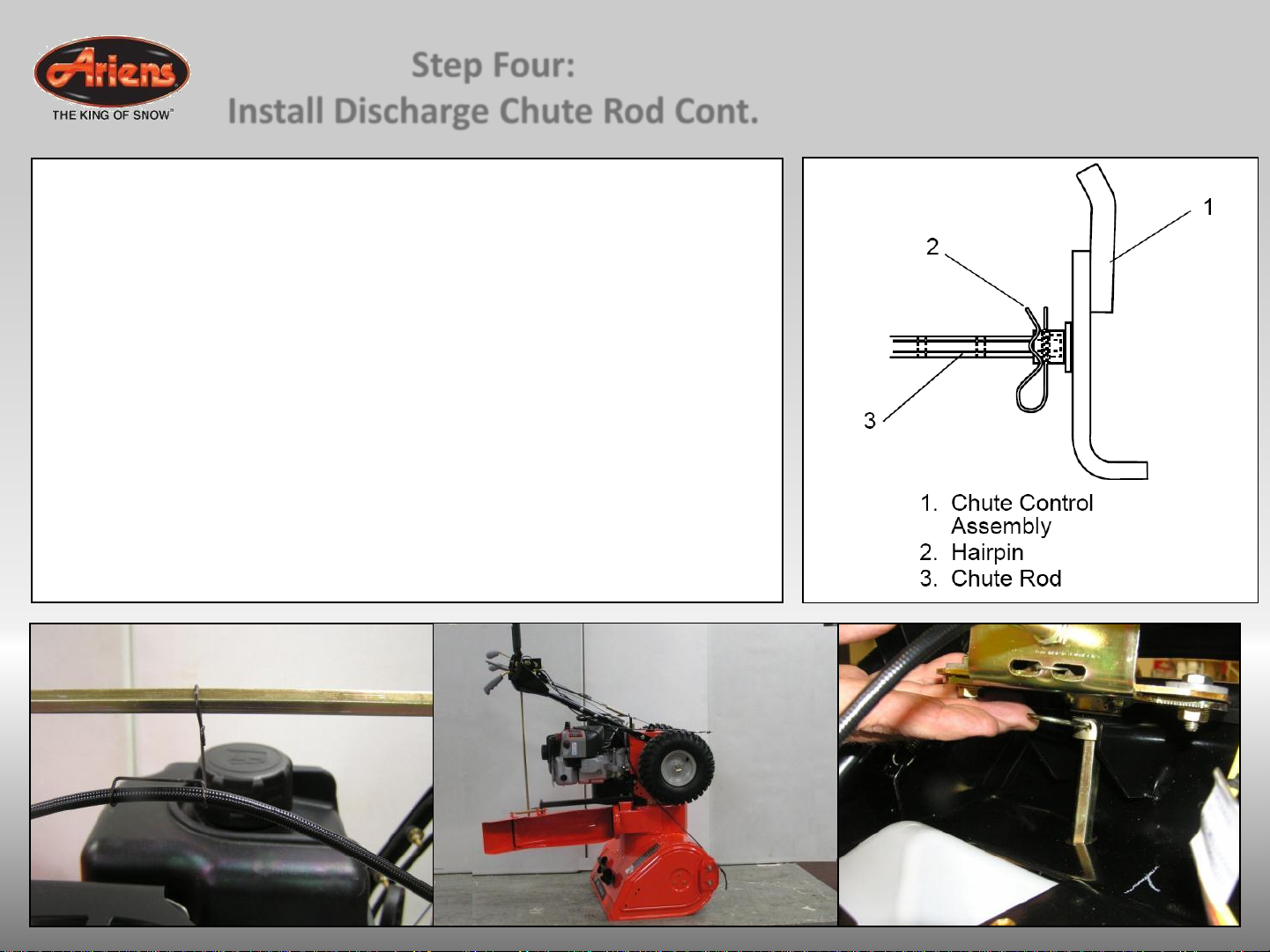
IMPORTANT: The hook will prevent the control cable from contacting
the engine or muffler guard.
NOTE: After the chute rod has been inserted through the hex hole in
the control assembly, placing the unit in the service position (see
Service Position in Owners Manual) will ease alignment and installation
of the hairpin.
4. Secure the chute rod to the control assembly with the hairpin
removed in step above using the end hole location. Insert the
hairpin with the loop end to the left of the chute rod so the control
assembly follows a full range of travel.
5. Replace the gear cover removed above.
6. Orient the chute and pedestal to its most vertical position and
tighten pedestal hardware to 15 –31 lbf-ft (20 –42 N•m).
7. Make sure the discharge chute rotates left and right when you
push the discharge chute control lever left and right.
NOTE: If chute does not stay in position, adjust as directed in
Discharge Chute in Owners Manual, or repair before operation.

Step Five: Install Remote
Deflector Control
1. Connect the cable end to the cable anchor on the discharge
deflector before clipping the cable to the cable bracket on the
discharge chute.
2. Route deflector remote cable along the left side of the chute
pedestal.
3. Insert the barrel on the cable end into the bracket on left side of
chute deflector.
4. Hold seal out of the way while routing the cable through the bracket
on the left side of the discharge chute, and then push the cable
fitting into the bracket.
5. Push the seal securely over the end on the cable fitting to prevent
water from entering the cable.
6. Check deflector travel. Adjust nut on cable end under handlebar to
obtain full travel, if necessary (see Remote Deflector Control in
Owners Manual.

Step Six:
Connect Battery
1. Remove wing nuts
from battery cover.
2. Install wire lead to
battery terminal.
3. Install battery cover
and tighten wing
nuts.

Step Seven:
Check Function of Dual Handle Interlock
Without the engine
running, press down
(engage) both clutch
levers. Release
attachment clutch lever.
Attachment clutch should
remain engaged until
traction clutch lever is
released, then both
clutches must disengage.
If they do not, contact your
Dealer for repairs.

Step Eight:
Check Tire Pressure
Check tire pressure and
adjust to the pressure
listed on tire sidewall.

Check oil level in auger
gearcase
(see Check Auger
Gearcase in Owners
Manual).
Step Nine:
Check Auger Gearcase Oil

IMPORTANT: The engine
is shipped with oil
in crankcase. Refer to
Engine Manual for
detailed instructions.
Step Ten:
Check Engine Crankcase Oil

Fill fuel tank. DO NOT
OVERFILL! See
FILLING FUEL TANK in
Owners Manual.
Step Eleven:
Fill Engine Fuel Tank

Step Twelve: Starting the Engine

Starting Engine / Step A:
Throttle
Move the throttle
control lever to the
fast position.
Operate the engine
with the throttle
control lever in the
fast position.

Starting Engine / Step B:
Fuel Valve
Turn the fuel shut-
off valve to the ON
position.

Starting Engine / Step C:
Key
Insert the key and turn
to the on/start position.

Starting Engine / Step D:
Choke
Turn the choke
control knob to the
choke position.
NOTE: Choke is
usually
unnecessary
when restarting a
warm engine.

Starting Engine / Step E:
Prime
Push the primer two
times.
NOTE: Priming is
usually unnecessary
when restarting a warm
engine.

Starting Engine / Step F:
(Manual Start)
Firmly hold the starter
cord handle. Pull the
starter cord handle
slowly until resistance
is felt, then pull rapidly.
NOTE: If the engine
does not start after
repeated attempts, go
to
BRIGGSandSTRATTON.COM
or call 1-800-233-3723.
Other manuals for Sno-Thro Pro 36
1
Table of contents
Other Ariens Snow Thrower manuals