ARK G965 User manual

Electronic Emission Notices
Federal Communications Commission (FCC) Statement
This equipment has been tested and found to comply with the limits for a Class B digital
device, pursuant to Part 15 of FCC ules. These limits are designed to provide reasonable
protection against harmful interference in a residential installation. This equipment
generates, uses and can radiate radio frequency energy and, if not installed and used in
accordance with instructions contained in this manual, may cause harmful interference
to radio and television communications. However, there is no guarantee that interference
will not occur in a particular installation.
If this equipment does cause harmful interference to radio or television reception, which
can be determined by turning the equipment off and on, the user is encouraged to try to
correct the interference by one or more of the following measures:
- EO IENT O ELOCATE THE ECEIVING ANTENNA
- INC EASE THE SEPA ATION BETWEEN THE EQUIPMENT AND THE ECEIVE
- CONNECT THE EQUIPMENT INTO AN OUTLET ON A CI CUIT DIFFE ENT F OM
THAT OF THE ECEIVE
- CONSULT THE DEALE O AN EXPE IENCED AUDIO/TELEVISION TECHNICIAN
NOTE: Connecting this device to peripheral devices that do not comply with Class B
requirements, or using an unshielded peripheral data cable, could also result in
harmful interference to radio or television reception.
The user is cautioned that any changes or modifications not expressly approved
by the party responsible for compliance could void the users authority to operate
this equipment.
To ensure that the use of this product does not contribute to interference, it is
necessary to use shielded I/O cables.
Copyright
This manual is copyrighted with all rights reserved. No portion of this manual may be
copied or reproduced by any means.
While every precaution has been taken in the preparation of this manual, no responsibility
for errors or omissions is assumed. Neither is any liability assumed for damages resulting
from the use of the information contained herein.
Trademarks
All brand names, logos and registered trademarks mentioned are property of their
respective owners.

Technical eference Booklet
TABLE OF CONTENTS
HARDWARE CONFIGURATION .................................................................... 4
Key Features .................................................................................................. 4
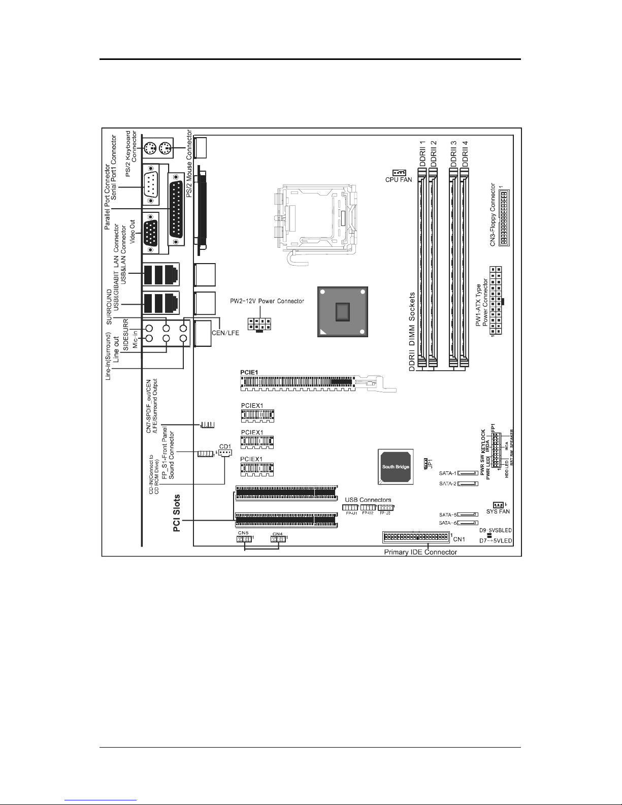
MOTHERBOARD LAYOUT ............................................................................ 7
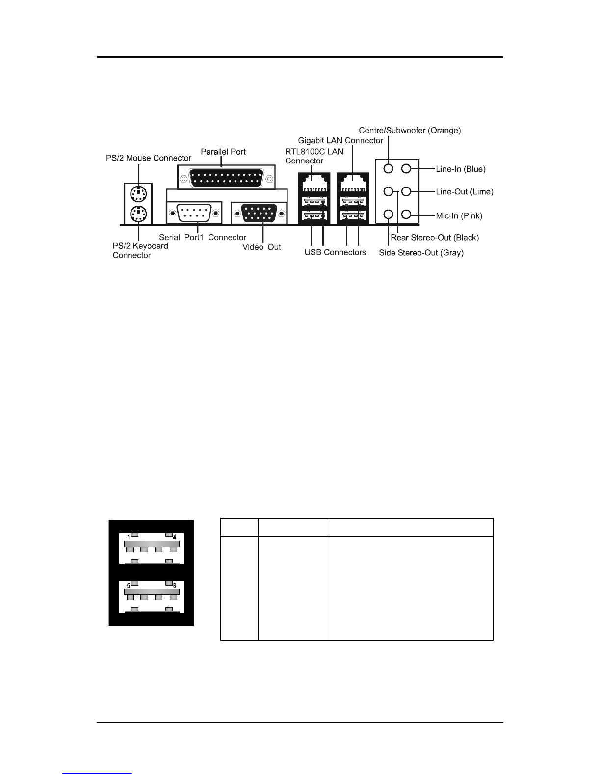
REAR PANEL ................................................................................................ 8
CONNECTORS ............................................................................................. 10
Floppy Disk Drive Connector - CN3 ...................................................... 10
SPDIF-In/Out Header - CN7 (optional) ................................................. 11
Fan Power Connectors - CPUFAN/SYSFAN (optional) ........................ 12
CD-IN Connector - CD1 (optional) ........................................................ 13
Serial ATA Hard Disk Connectors -
SATA-1/SATA-2/SATA-5/SATA-6 (optional) ............................................... 14
Front Panel Audio Header - FP-S1 ........................................................ 16
IEEE 1394 Connector - CN4/CN5 ......................................................... 17
Power LED - D9, D7 (optional).......................................................................17
USB Connectors - FP-U1/FP-U2/FP-U3 (optional) ............................... 19
Front Panel Header - FP1 ...................................................................... 20
JUMPER SETTING ....................................................................................... 21
CMOS Clear - JP1 .................................................................................. 21
SLOTS ......................................................................................................... 22
CPU INSTALLATION .................................................................................... 23
MEMORY CONFIGURATIONS ...................................................................... 2
DD II DIMM Sockets Location............................................................... 26
Install DD II DIMMs ............................................................................... 27
Memory Configurations ......................................................................... 27
BIOS SETUP ................................................................................................ 28
About the Setup Utility ............................................................................ 28
The Standard Configuration .................................................................. 28
Entering the Setup Utility........................................................................ 28
Main Menu .............................................................................................. 29
Standard CMOS Features ..................................................................... 30
Advanced BIOS Features ....................................................................... 31
Advanced Chipset Features .................................................................. 31
Integrated Peripherals ........................................................................... 31

!
Power Management Setup ..................................................................... 31
PNP/PCI Configurations ........................................................................ 31
PC Health Status ................................................................................... 31
Frequency/Voltage Control..................................................................... 31
Set Supervisor/User Password ............................................................. 32
Save & Exit Setup ................................................................................... 32
Exit Without Saving................................................................................. 32
Flash Update Procedure ....................................................................... 33
REALTEK HD AUDIO DRIVER SETUP ........................................................... 34
Getting Started ....................................................................................... 34
Sound Effect ........................................................................................... 34
Environment Simulation ........................................................................ 34
Equalizer Selection ................................................................................ 35
Frequently Used Equalizer Setting ........................................................ 35
Karaoke Mode ........................................................................................ 35
Mixer ....................................................................................................... 36
Playback control ............................................................................... 36
ecording control ............................................................................. 37
Audio I/O ........................................................................................... 38
Speaker Configuration ..................................................................... 39
Global Connector Settings............................................................... 40
S/PDIF .............................................................................................. 41
Speaker Calibration ......................................................................... 41
Microphone....................................................................................... 42
Noise Suppression.......................................................................... 42
Beam Forming ................................................................................. 42
Acoustic Echo Cancellation ............................................................. 42
Audio Demo ..................................................................................... 43
Information ....................................................................................... 43
APPENDIX .................................................................................................... 44

"
Technical eference Booklet
HARDWARE CONFIGURATION
Key Features :
Chipset
Intel® G965/P965 Chipset.
Processor
Supports Intel® Celeron® , Pentium® 4, Pentium® D, CoreTM 2 Duo
processors in the LGA775 -pin package (with 0.8V~1. V voltage).
Supports 64-bit PSB (Processor System Bus) frequency of 533MHz
/800MHz/1066MHz (133MHz/200MHz/266MHz bus clock).
Supports Hyper-Threading Technology.
VRM 11.0 (Voltage Regulator Modules) Onboard
Flexible motherboard design with onboard V D11.0, easy to upgrade
with future Intel® Celeron, Pentium® 4, Pentium® D, CoreTM 2 Duo ,
processors.
0.03125V to 1.600V in 6.25mV steps for V M11.0.
System Memory
A total of four 240 pin DD II SD AM sockets.
Dual-channel (128 bits wide) DD II memory interface.
Supports 128Mb,256Mb,512Mb technologies implemented
as X8,X16 devices.
Supports DD II533/DD II667/DD II800.
Support for Non-ECC memory only.
Maximum memory size: 8GB.
Onboard I/O
_One ECP/EPP parallel port.
_One floppy port which supports two FDD of 1.44MB, 2.88MB capacity.
_Ten USB ports (optional).
_PS/2 keyboard support.
_PS/2 mouse support.
_One Front Panel Sound Connector.
_Infrared (IrDA) support via a header.
One 16550 Compatible UA T serial port.
System BIOS
PnP, APM, ATAPI for Windows® 2000/XP.
Full support of ACPI & DMI.
Auto detects and supports LBA harddisks with capacities over 160GB.
Easy to upgrade BIOS by end-user.

#
Plug-and-Play
Supports Plug and Play specification 1.1.
Plug and Play for Windows®2000 as well as Windows®XP.
Fully steerable PCI interrupts.
Onboard Realtek RT8111B PCI Express Gigabit LAN (optional)
Full compliance with IEEE 802.3u 100 Base-T specifications
and IEEE 802.3X Full Duplex Flow Control.
Supports 10 Mb/s, 100 Mb/s and 1000 Mb/s operation.
Supports Wake-On-LAN function and remote wake-up.
Onboard Realtek RT8100C LAN (optional)
Integrated 10/100 transceiver.
Supports Full Duplex flow control (IEEE802.3x)
Fully compliant with IEEE802.3, IEEE802.3u, IEEE802.3ab.
Supports Wake-On-LAN function and remote wake-up.
Transmit/ eceive FIFO (8K/64K) support.
Onboard VGA (optional)
Core Frequency of 400MHz.
3D Setup ender Engine.
High Quality Texture Engine.
3D Graphics asterization Enhancements.
Full 2D H/W Acceleration.
Motion Video Acceleration.
Up to 2048x1536 in 8 bit Color at 85Hz efresh.
H/W Motion Compensation Assistance for S/W MPEG2 Decode.
Software DVD at 30fps.
Integrated 24-bit 350MHz AMDAC.
PCI Express Graphics interface
_One 16-lane (X16 port) PCI Express graphics port, fully compliant
with the PCI Express Base Specification revision 1.0a.
_A base PCI Express frequency of 2.5GB/s only.
_PCI Express support and Enhanced Addressing Mechanism.
PCI ExpressX1 Ports (optional)
_Full PCI Express 1.0a compliant.
_Three virtual channel support for full isochronous data transfers.
_Support for full 2.5GB/s bandwidth in each direction per X1 lane.
Onboard IEEE1394 OHCI Link Controller (optional)
Compliant with 1394 OHCI specifications v1.0 and v1.1.
Integrated 400Mbit 2 ports PHY.

$
Technical eference Booklet
Static electricity can harm delicate components of the motherboard.
To prevent damage caused by static electricity, discharge the static
electricity from your body before you touch any of the computers
electronic components.
Onboard HD Sound Audio
Integrated ealtek ALC883 controller.
Fully Sound and Sound Blaster compatible.
Full-Duplex 4 24-bit two-channel DACs and 3 stereo 20-bit ADCs.
PnP and APM 1.2 support.
Windows® 2000/XP ready.
Line-in, Line-out, Mic-in, SPDIF-in, SPDIF-out.
Supports HD Sound codec for eight channel sound output.
Expanded USB Support
Includes 5 UHCI host controllers, increasing the number of external
ports to ten.
Includes 2 EHCI USB2.0 Host Controller that supports all ten ports
(Bandwidth is shared between the ten ports).
Power Management
Supports SMM, APM and ACPI.
Break switch for instant suspend/resume on system operations.
Energy star Green PC compliant.
Hardware monitoring circuit provides voltage, temperature, fan speed,
etc. monitoring (optional).
Supports suspend-to- AM (ST ) (optional).
External Modem ing-in Wake-up support.
Integrated Serial ATA host Controller
Independent DMA operation on four ports (optional).
Data transfer rates of 300Mb/s.
AID feature support (optional).
Expansion Slots
1 PCI Express X16 slot.
_2 PCI bus slots - ver. 2.1 compliant (optional).
3 PCI Express X1 slots (optional).
Onboard JM20330 Serial ATA to IDE bridge (optional)
Supports ATA/ATAPI PIO mode 0 to 4.
_Supports ATA/ATAPI U1tra DMA of transfer rate 16.7, 25, 33, 48, 66,
100, 133, and 150MB/s.

%
Motherboard Layout
The following diagram shows the relative positions of the jumpers, connectors,
major components and memory banks on the motherboard.
# SATA6 is optional
# CN1 is optional
NOTE :
1) Be sure to check the HDD cable orientation in order to match the colored strip to the pin 1 end
of the connector.
2) When you start up the system, please wait for 5 seconds after you power on AC.
3) Adding a metal spaced plate to the back of the Socket 775 is not recommended as this will short
motherboard components and damage the system.
PKE;;9$Wsgoix
J
S
\
G
S
R
R
V
I
Q
S
Z
I
MIII57=8Gsrrigxsvw$

&
Technical eference Booklet
PIN SIGNAL DESC IPTION
1 VCC +5V/5VSB (optional)
2 -Data 0 Negative Data Channel 0
3 +Data0 Positive Data Channel 0
4 GND Ground
5 VCC +5V/5VSB (optional)
6 -Data 1 Negative Data Channel 1
7 +Data 1 Positive Data Channel 1
8 GND Ground
Rear Panel
The back panel provides the following connectors:
Mouse Connector
The mainboard provides a standard PS/2® mouse mini DIN connector for
attaching a PS/2® mouse. You can plug a PS/2® mouse directly into this
connector.
Keyboard Connector
The mainboard provides a standard PS/2® keyboard mini DIN connector for
attaching a PS/2® keyboard. You can plug a PS/2® keyboard directly into this
connector.
USB 2.0 Connector
The mainboard provides a UHCI (Universal Host Controller Interface) Universal
Serial Bus root for attaching USB devices such as keyboard, mouse or other
USB-compatible devices. You can plug the USB device directly into the
connector.
USB 2.0 Connector DescriptionUSB 2.0 Connector

'
Serial Port Connector: COM1
The Port is 16550A high speed communication port that send/receive 16bytes
FIFOs. You can attach a serial mouse or other serial devices directly to the
connectors.
Video Out Connector (Optional)
The mainboard provides a Video out port to connect a 15-pin analog video
monitor.
LAN Jack Connector (Optional)
The mainboard provides one standard J-45 jack for connecting to a Local
Area Network (LAN). You can connect the network cable to the LAN jack.
Onboard Realtek RTL8111B PCI Express Gigabit LAN
Full compliance with IEEE 802.3u 100 Base-T specifications
and IEEE 802.3X Full Duplex Flow Control.
Supports 10 Mb/s, 100 Mb/s and 1000 Mb/s operation.
Supports Wake-On-LAN function and remote wake-up.
8 Channel HD Audio
Option select of 2, 6, or 8 channel audio from onboard ALC883 High
Definition audio compliant CODEC with 20-bit ADC and 24-bit DAC resolution.
- Support CD-In, SPDIF-in and SPDIF-out.
- Optical & Coaxial SPDIF-out available on rear panel.
- Support jack detection for easy audio device installation.
Rear panel audio jacks configuration:
Audio Jack Color 2 Channel Channel 8 Channel
Blue Line-In Line-In Line-In
Lime Line-Out Front Stereo-Out Front Stereo-Out
Pink Mic-In Mic-In Mic-In
Gray -- -- Side Stereo-Out
Black -- ear Stereo-Out ear Stereo-Out
Orange -- Centre & Subwoofer Centre & Subwoofer

Technical eference Booklet
CONNECTORS AND HEADERS
The motherboard provides connectors to connect to the FDD, IDE HDD, USB
Ports and to CPU/System FAN etc.
Floppy Disk Drive Connector - CN3
The mainboard provides a standard floppy disk drive connector that supports
1.44M, 2.88M floppy disk types.
Hard Disk Connectors - CN1
The mainboard has a 32-bit Enhanced PCI IDE and Ultra DMA 33/66/100
controller that provides PIO mode 0~4, Bus Master, and Ultra DMA 33/66/100
function. You can connect up to two hard disk drives, CD- OMs, 120MB Floppy
(reserved for future BIOS) and other devices.
CN1 (Primary IDE Connector)
CN1 connects can connect a ide device, please set the jumper on IDE device
as Master.
CN3
CN1 1
1
J
S
\
G
S
R
R
V
I
Q
S
Z
I

SPDIF-In/Out Header - CN7 (optional)
This header provides a SPDIF (Sony/Philips Digital Interface) Input & output to
digital multimedia device through fiber or coaxial connector.
CN7 Pin Definition
PIN SIGNAL
1 SPDIP-out
2 SPDIF-in
3.4.5.6 NC
7.8 GND
SPDIF-in 2 8
7
SPDIF-out1
CN7
J
S
\
G
S
R
R
V
I
Q
S
Z
I

Technical eference Booklet
Fan Power Connectors - CPUFAN/SYSFAN (optional)
The CPUFAN (processor fan) and SYSFAN (system fan) support system cool-
ing fans using +12V via a four/three-pin head connector. When connecting the
wire to the connectors, always take note that the red wire is the positive and
should be connected to the +12V, the black wire is Ground and should be
connected to GND. If the mainboard has a System Hardware Monitor chipset
on-board, you must use a specially designed fan with speed sensor to take
advantage of the CPU fan control.
SYS FAN
CPU FAN
1
1
J
S
\
G
S
R
R
V
I
Q
S
Z
I

!
CD-IN Connector - CD1 (optional)
The connector is for CD- OM Drive.
1
PIN Assignment
1 CD-L
2 GND
3 GND
4 CD-
CD1
CD1
J
S
\
G
S
R
R
V
I
Q
S
Z
I

"
Technical eference Booklet
Serial ATA Hard Disk Connectors -
SATA-1/SATA-2/SATA-5/SATA- (optional)
The mainboard has four SATA connectors. The mainboard provides optional
dual high-speed Serial ATA interface ports, SATA-1, SATA-2, STAT-5&SATA-6.
Each supports 1st generation serial ATA data rates of 300MB/s. Both connector
types are fully compliant with Serial ATA 2.0 specifications. Each Serial ATA
connector can connect to 1 hard disk device.
PIN SIGNAL
1 GND
2 TXP
3 TXN
4 GND
5 XN
6 XP
7 GND
SATA-2
SATA-1
SATA-5
SATA-
J
S
\
G
S
R
R
V
I
Q
S
Z
I

#
Serial ATA Cable
Please do not fold the serial ATA cable at a 90 degree angle as this
will cause a loss of data during the transmission.
Serial ATA Hard Disk Devices Power Cable (optional)
Connect one end of the SATA cable to the mainboard, and connect the other
end to the SATA Hard Disk.

$
Technical eference Booklet
Front Panel Audio Header - FP_S1
Note: In order to utilize the front audio header, your chassis must have a
front audio connector. Also please make sure the pin assignment on the
cable is the same as the pin assignment on the motherboard header. To
find out if the chassis you are buying supports front audio connection,
please contact your dealer.
FP_S1
FP_S1 - Pin Definition
Pin Signal Description
1 PO T 1L Analog Port1 - Left channel
2 GND Ground
3 PO T 1 Analog Port 1 - ight channel
4 P ESENCE Active low signal - signals BIOS that a
High Definition Audio dongle is connected to
the analog header. P ESENCE=0 when
a High Definition Audio dongle is connected.
5 PO T 2 Analog Port 2 - ight channel
6 SENSE1_ ETI N Jack detection return from front panel JACK1
7 SENSE_SEND Jack detection sense line from the High
Definition Audio Codec jack detection
resistor network
8 KEY Connector Key
9 PO T 2L Analog Port2 - Left channel
10 SENSE2_ ETI N Jack detection return from front panel JACK2
10
2
1
1
2
9
10
J
S
\
G
S
R
R
V
I
Q
S
Z
I

%
IEEE 1394 Connector - CN4/CN5 (optional)
The mainboard provides two 1394 pin headers that allow you to connect IEEE
1394 ports.
CN4
CN5
1
210
1
210
Power LED - D9, D7 (optional)
The green LED lights when the system is in the power-on state.
The red LED lights whenever AC power is attached, irrespective of whether the
system is powered-on, powered-off or in standby mode.
D7- +5VLED (Green)
D9- 5VSBLED ( ed)
J
S
\
G
S
R
R
V
I
Q
S
Z
I
J
S
\
G
S
R
R
V
I
Q
S
Z
I

&
Technical eference Booklet
PIN SIGNAL
1TPA+
2TPA-
3 Ground
4 Ground
5 TPB+
6 TPB-
7 Cable power
8 Cable power
9 Key (no pin)
10 Ground
IEEE1394 Pin Definition
IEEE 1394 Cable (optional)

'
USB Connectors - FP-U1 / FP-U2 / FP-U3 (optional)
This mainboard has ten USB ports. Some computer cases have a special
module that mounts USB ports at the front of the case. If you have this kind of
case, use the auxiliary USB connectors FP-U1/FP-U2/FP-U3 to connect the
front mounted ports to the mainboard.
10
2
1
FP-U1
PIN Assignment
1 VCC
2 VCC
3 USBP0-
4 USBP1-
5 USBP0+
6 USBP1+
7 GND
8 GND
9 KEY
10 OC#
FP-U1 / FP-U2 / FP-U3
FP-U2
10
2
1
FP-U3
10
2
1
J
S
\
G
S
R
R
V
I
Q
S
Z
I

Technical eference Booklet
Front Panel Header - FP1
The mainboard provides one front panel connector.
FP1
NC
VCC
KEY
KEYLOCK
GND
I X
SPEAKE
GND
KEY
I TX
NC
VCC
GND
KEY
GND
PW _SW
ESET
NC
KEY
GND
PW_LED-
PW_LED+
HDD_LED-
HDD_LED+
24 23
16
1718
20
22 21
19
15
13
7
11
9
5
3
1
14
6
8
10
12
2
4
J
S
\
G
S
R
R
V
I
Q
S
Z
I
This manual suits for next models
1
Table of contents