Cutting, connecting and wiring
Warning:
Do not connect LED tape to household 120V AC power.
Only connect to low voltage 12V DC power.
Always maintain polarity when connecting LED tape lighting and low voltage
power wires.
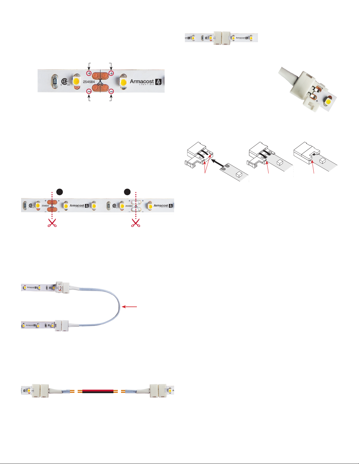
Positive
Negative
Be sure to connect positive wires to positive (+ to +), and negative wires to
negative (– to –). Polarity is easily identified with + and – markings on LED
tape as shown.
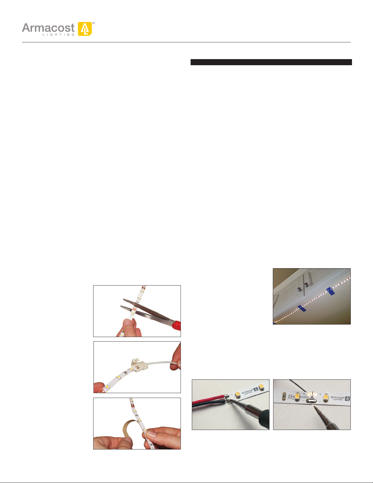
Cut with scissors
This tape light model can be cut every 3 LEDs, or about every 2".
■ To use solderless LED Snap Connectors, cut the LED tape with
scissors directly in the center of the copper pad as shown in position
“A” below.
■ You can also cut the tape at position “B,” however, do not use Snap
Connectors on these soldered tape light joints..
■ You can also solder 12V power lead wires at these joints.
Cut tape at center
of copper pads
B
Okay to cut at solder
joints, but do not
use connector
A
Wire Lead Snap Connectors
Wire Lead Snap Connectors are used for going around corners or, when cut in
half, to create two power leads (“jumper” cables) for linking and extending
power wires to LED tape lighting in other areas.
IMPORTANT: Always use the + / – indicators printed on the tape light to
maintain polarity.
To make longer
“jumper” cables
Cut in half to
create two wire
lead connectors
that can be
spliced to longer
wires in order to
get power to LED
tape strips in
other areas.
Bridging gaps and extending wires
To increase the length of wire between two LED strips, simply splice in the
extra length of wire required, 18 AWG is generally recommended. Be sure
to match polarity, + to +, - to -. Do not coil wire; shorter lengths and thicker
wire will mean less voltage drop and higher brightness. For an online voltage
drop calculator, visit armacostlighting.com/installation.
(+)
(–)
length to
fit needs
(–)
(+)
(–)
(+) (+)
(–)
Be sure all 12V connections are secure and sealed. Options include soldering
and heat-shrink tubing, crimp connectors, terminal blocks, wire nuts, etc.
Splice Snap Connectors
Splice Snap Connectors are for joining two strips to create a continuous
run of LED lighting.
Splice Snap Connector
(+) (+)
(–) (–)
If the + / – marks do not line up,
flip the tape and use the opposite
end for proper alignment.
How to use Snap Connectors
■ Pry open lid on the snap connector
(splice connector has two lids).
■ Using a side-to-side motion, carefully
slide tape strip into connector channel
as shown below so the copper pads on
the tape are positioned underneath the
connector contacts.
■ Close and snap down lid connector.
■ Perform a power test to be sure connection is secure and LEDs light
before final installation.
■ If LEDs do not light, or LEDs flicker, repeat the steps outlined above.
Insert tape into channel
under contact tabs
Be sure tape slides
into channel groove
Press down lid
until it snaps closed
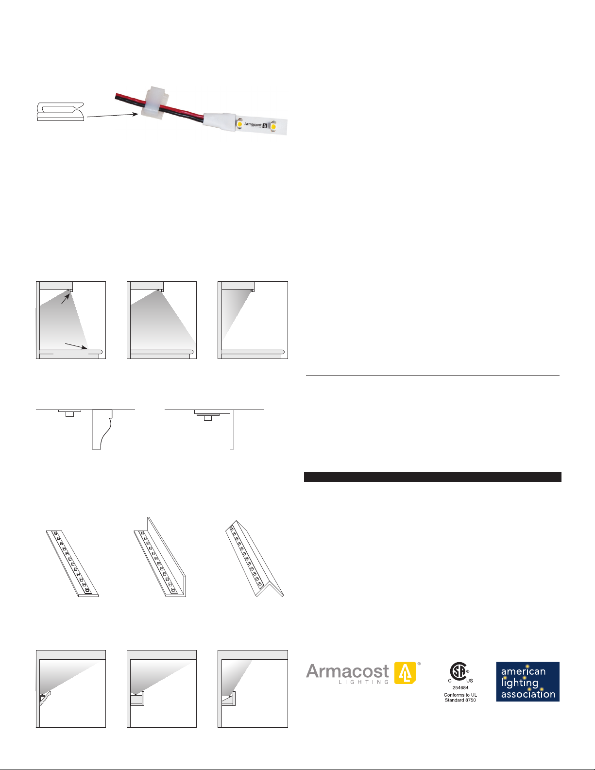
Surface preparation and installing
peel-and-stick LED tape lighting
Before removing the 3M tan colored paper backing, it is important to test the
LED strip in the space you intend to light. Once the paper backing is removed
and the lighting is fully installed, you cannot reposition or move the LED tape
light to another location. The tape may not stick securely.
1. Power the LED tape lighting and temporarily hold or tape into position with
painter’s tape or masking tape – do not remove the 3M paper backing.
2. Adjust the lighting to various angles and positions to get the desired
level of illumination and lighting appearance. If the LEDs create
undesirable bright spots on walls, or reflections, reposition the tape
light strip farther away from surfaces or try a different mounting angle.
3. Once you have determined your final mounting position, clean and prep
the surface to ensure the 3M self-adhesive backing will adhere properly.
IMPORTANT
■ Mounting surfaces should be smooth, clean, completely dry, dust free
and above 60ºF (15 ºC) before installing/sticking the LED tape lighting.
■ Thoroughly clean all mounting surfaces with a 50:50 mixture of
isopropyl alcohol and water. For extra dirty surfaces, first use 100%
alcohol or acetone. Avoid the use of household cleaners and polishes
that may leave behind residues. Also avoid common rubbing alcohol
because it frequently contains oils that can interfere with the
performance of the 3M adhesive tape.
■ For best adhesion – especially when sticking to the underside of
cabinets – lightly sand the surface where you will mount the tape
lighting. This includes unfinished woods, plastics/laminates and all
painted surfaces. Use a very fine grit sandpaper (150-300 grit) and sand
in a circular motion rather than straight-line motion for best results.
■ When installing on painted surfaces, paint should be fully cured based
on manufacturer's cure time.
■ Be careful not to peel off the 3M adhesive from LED strip, just remove
the tan paper backing. If using LED Snap Connectors, carefully cut the
tan backing when it enters the connector. It is beneficial to leave the
3M backing paper inside the connector.
■ 3M sticky back tape requires pressure to activate the adhesive. Using a
clean dry cloth over your fingers and working from one end to the other,
firmly press the tape down the entire length of the strip.
2 3
Power supply location and voltage drop
The power supply that provides 12V DC power to your LED tape lighting
operates on 120V AC household current. The shorter the wire lead
between the power supply and the LED tape lighting, the brighter the
lights will be. If the lights farthest from the power supply appear dim,
it is due to voltage drop.
Voltage drop only becomes undesirable if you notice the brightness in one
area of your lighting is objectionably different than in another area. As a
practical approach, test your lighting prior to final installation. Refer to the
chart below for recommended lengths of power feed wires using 22 and
18 AWG wires.
Excessive voltage drop = reduced brightness and color accuracy
Shorter and/or thicker wires = higher brightness and color consistency
Longer LED tape = an increase in voltage drop
Recommended maximum length of 12V power wires
from power supply to LED lighting
22 AWG WIRE 18 AWG WIRE
If your LED tape
light length is:
Max wire length
to tape light
If your LED tape
light length is:
Max wire length
to tape light
12 Feet 10 Feet 12 Feet 20 Feet
24 Feet 8 Feet 24 Feet 16 Feet
36 Feet 6 Feet 36 Feet 12 Feet
48 Feet 4 Feet 48 Feet 8 Feet
For an online voltage drop calculator, visit armacostlighting.com/
installation.
Switching and dimming options
If you do not have a switched 120V AC outlet for your LED power supply,
consider an optional Armacost Lighting wireless wall switch or an Armacost
12V LED dimmer switch with optional RF wireless designer-style touchpad.
Important: Do not use a standard AC wall dimmer with your power supply unless
the power supply clearly states that it is dimmable with 120V AC dimmers.
For power supply options visit armacostlighting.com/power-supply.
TYPICAL CONNECTING AND SWITCHING OPTIONS
120V
AC OUTLET
12V DC
POWER SUPPLY
Armacost
WIRELESS
WALL SWITCH
WIRELESS
SWITCH
RECEIVER
120V
AC OUTLET
12V DC
POWER SUPPLY
Armacost
WIRELESS
LED DIMMER
Armacost
LED DIMMER
AC OUTLET
POWER SUPPLY
SWITCH
Armacost
LED DIMMER
12V BATTERY FUSE
PROTECTION 12V SWITCH
120V
AC OUTLET
12V DC
POWER SUPPLY
Armacost
WIRELESS
WALL SWITCH
WIRELESS
SWITCH
RECEIVER
120V
AC OUTLET
12V DC
POWER SUPPLY
Armacost
WIRELESS
LED DIMMER
Armacost
LED DIMMER
Armacost
LED DIMMER
12V BATTERY FUSE
PROTECTION 12V SWITCH
Interior RV and boat applications can be powered directly by 12V battery
Configuration options
RibbonFlex Pro offers endless connection options to fit virtually any
installation imaginable. LED tape strips can be installed in series (strips
connected or wired end-to-end) or in parallel (multiple legs of LED strips
or series of strips wired directly to a single power supply).
LED tape lighting power requirements are based on several factors,
including your configuration (Straight Run, Center Feed/Loop Back or
Array), voltage drop, and the length limitations of the LED tape lighting.
TYPICAL CONFIGURATIONS
Straight Run
Only one end of the
LED strip is powered.
Multiple strips can be
connected in a series for
a continuous run. LEDs
farther away from the power supply may appear dimmer due to voltage
drop, especially if longer wires are used in between to connect strips.
Center Feed / Loop Back
Either power two
equal legs of tape
lighting from the
center or loop back
and power both
ends of the LED
tape. These
configurations will
produce more
consistent brightness and color over the length of the strip. A loop back
is excellent for room perimeter tray ceiling or cove lighting.
Array
An array uses two or
more legs of various
lengths wired to a
power supply in a
parallel connection.
You will need to
calculate total
wattage used in an array to guard against overloading the power supply.
Choosing a power supply
Refer to the charts below for the recommended maximum lengths of LED
tape lighting based on your configuration and choose a power supply
rated greater than your needs – you cannot overpower LED tape lighting.
The LED power requirements shown below are based on 100% full power
brightness levels and do not represent every possible installation scenario.
Do not use a standard 120V AC wall dimmer with your power supply unless the
power supply clearly states that it is dimmable with AC dimmers.
For power supply options visit armacostlighting.com/power-supply.
Maximum length of LED tape based on configuration type and power supply
Power Supply Straight Run Center Feed / Loop Back
6 Watt 3.3 ft (1.0m) Not recommended
15 Watt 10.5 ft (3.2m) 9.0 ft (2.75m)
30 Watt 24.0 ft (7.3m)* 20.0 ft (6.0m)
60 Watt 24.0 ft (7.3m)* 48.0 ft (14.6m)
*Due to voltage drop, exceeding 24-foot lengths will cause LEDs farthest from the
power supply to appear dimmer. It is okay to use a higher wattage power supply,
however, it will not reduce the impact of voltage drop.
Array power supply calculation
Due to voltage drop, longer lengths of LED tape will use fewer watts per
foot than shorter lengths. The total watts used in an array layout depend on
the wattage requirement of each leg and overall voltage drop within your
connection wires. A leg can be a single LED strip or series of strips connected
end-to-end. Various legs are wired in parallel directly to the power supply.
Calculate the wattage for each leg by multiplying watts per foot by the
length of LED lighting in the leg. Include only the lengths of LED tape
in your calculation, not the connecting wires. Add each leg’s wattage
requirement together to determine the total watts needed to power your
array and select a power supply that exceeds the total watts needed.
Length of leg
(LED tape light only) 1 to 5 feet 6 to 11 feet 12 to 15 feet
Watts used per foot 1.8 watts/ft 1.6 watts/ft 1.4 watts/ft
POWER
SUPPLY
POWER
SUPPLY
LEG 1 LEG 2
POWER
SUPPLY
POWER
SUPPLY
LEG 3
LEG 1
LEG 2