Armstrong Air BCE7S Series User manual

507746-01 Issue 1821 Page 1 of 39
NOTE: Special procedures are required for cleaning the all-aluminum coil in this unit. See Page 37 in this instruction
for information.
IMPORTANT INFORMATION FOR INSTALLER
ABC
HORIZONTA L DRAIN PAN (SEE
UPFLOW APPLICATIONS ON PAGE
6 AND DOWNFLOW APPLICATIONS
ON PAGE 8 )
BLOWER HOUSING SUPPORT PADREFRIGERANT LINE PLUGS (SEE
BRAZING CONNECTION ON PAGE 10)
CHECK FOR AND REMOVE THE FOLLOWING ITEMS BEFORE OPERATING UNIT.
FOR PROPER OPERATION THE ELECTRIC HEAT (IF APPLICABLE) MUST BE
CONFIGURED (SET-UP) THROUGH THE AIR HANDLER CONTROL (AHC)
ELECTRIC HEAT SECTIONS MUST BE
CONFIGURED. IF INSTALLED, SEE
PROCEDURE IN FIGURE 22 ON PAGE 31.
H
H
CONFIGURE ELECTRIC HEAT
ECB27
IMPORTANT: WHEN ELECTRIC HEAT IS INSTALLED, THE
AIR HANDLER CONTROL MUST BE MANUALLY
CONFIGURED. SEE JUMPERS AND LINKS GUIDE ON
PAGE 19.
Save these instructions for future reference
INSTALLATION INSTRUCTIONS
BCE7S Series Air Handler
(P) 507746-01
*P507746-01*
Manufactured By
Allied Air Enterprises LLC
A Lennox International, Inc. Company
215 Metropolitan Drive
West Columbia, SC 29170
This manual must be left with the homeowner for future reference.
This is a safety alert symbol and should never be ignored. When you see this symbol on labels or in
manuals, be alert to the potential for personal injury or death.
Table of Contents
Unit Dimensions ..........................................................2
Model Number Identication........................................4
General Information ....................................................5
Shipping and Packing List ..........................................5
Installation Clearances ...............................................5
Requirements .............................................................5
Installation ...................................................................6
Brazing Connections ................................................10
Condensate Drain .....................................................12
Inspecting and Replacing Filters ..............................13
Sealing the Unit ........................................................13
Field Control Wiring ..................................................13
Air Handler Control Button, Display and Jumpers ....20
Unit Operating Sequences .......................................27
Operation...................................................................35
Repairing or Replacing Cabinet Insulation ................36
Homeowner Maintenance..........................................36
Professional Maintenance .........................................37
Checkout Procedures................................................37

507746-01Issue 1821Page 2 of 39
OPTIONAL
ELECTRIC HEAT
(FIELD-INSTALLED)
AIR
FLOW
LIQUID
LINE
SUCTION
LINE
SUPPLY AIR
OPENING
RETURN AIR
FILTER
LOW VOLTAGE
INLETS (TOP AND
RIGHT SIDE)
RETURN AIR
TOP VIEW
FRONT VIEW SIDE VIEW
BLOWER
PIPING PLATE DETAIL
(FOR UP-FLOW AND DOWN-FLOW POSITIONS)
A
CB
11‐1/16 (281)
D
FE
LIQUID LINE
SUCTION LINE
CONDENSATE DRAINS
(2) (HORIZONTAL)
COIL
3/4 (19)
3/4 (19)
5/8 (16) )52(1)61(8/5
5/8 (16)
1‐3/4 (44)
2
(51)
1‐1/8 (29) 4‐3/8 (111)
2‐3/4
(70)
5‐3/8
(137)
3‐1/2 (89)
OPTIONAL
ELECTRIC HEAT
(FIELD-INSTALLED) AIR FLOW
LIQUID
LINE
SUCTION
LINE
Return
Air Opening
SUPPLY
AIR
FILTER
SUPPLY AIR
TOP VIEW
FRONT VIEW
SIDE VIEW
BLOWER
A
B
C
11‐1/16 (281)
F
D
E
COIL
5/8 (16)
5/8 (16)
5/8 (16)
5/8 (16)
5/8 (16)
LOW VOLTAGE
(RIGHT SIDE)
LINE VOLTAGE
(LEFT SIDE)
DOWN-FLOW POSITION
1 (25)
UP-FLOW POSITION
CONDENSATE DRAINS
(2) (UP-FLOW AND
DOWN-FLOW)
FILTER ACCESS
FILTER ACCESS
H
G
H
G
LINE VOLTAGE
INLETS (TOP
AND LEFT SIDE)
5/8 (16)
5/8 (16)
Unit Dimensions
Upow and Downow Unit Dimensions - Inches (mm)
Common Dimensions
Dimension 24 30/36 42/48 60
in. mm in. mm in. mm in. mm
A49-1/4 1251 51 1295 58-1/2 1486 62-1/2 1588
B21-1/4 540 21-1/4 540 21-1/4 540 21-1/4 540
C20-5/8 524 22-5/8 575 24-5/8 625 24-5/8 625
D19-3/4 502 19-3/4 502 19-3/4 502 19-3/4 502
E19 483 21 533 23 584 23 584
F20 508 20 508 20 508 20 508
G24-5/8 625 26-3/8 670 27-7/8 708 27-7/8 708
H24-5/8 625 24-5/8 625 30-5/8 778 34-5/8 879

507746-01 Issue 1821 Page 3 of 39
LIQUID
LINE
SUCTION
LINE
Supply
Air
Opening
FILTER
LOW VOLTAGE
INLETS (BOTTOM
AND RIGHT
SIDE)
TOP VIEW
FRONT VIEW
BLOWER
H
B
C
D
LIQUID
LINE
SUCTION
LINE
CONDENSATE
DRAINS (2)
(UP-FLOW
AND
DOWN-FLOW)
CONDENSATE
DRAINS (2)
(HORIZONTAL)
Coil
3/4 (19)
3/4 (19)
1‐1/2
(38)
1‐3/4
(44)
5‐3/4
(46)
2
(51)
1‐1/8
(29)
RETURN AIR
OPENING
F
E
5/8 (16)
5/8 (16)
5/8 (16)
END VIEW
AIR
FLOW
OPTIONAL ELECTRIC
HEAT (FIELD-INSTALLED)
11‐1/16
(281)
LINE VOLTAGE
INLETS (TOP
AND RIGHT
SIDE)
5‐3/8
(137)
4‐3/8
(111)
LIQUID
LINE
SUCTION
LINE
Supply
Air Opening
FILTER
LOW VOLTAGE
INLETS (TOP AND
LEFT SIDE)
END VIEW
BLOWER
B
C
D
Coil
3/4 (19)
3/4 (19)
3/4 (19)
Return
Air Opening
F
E
5/8 (16)
5/8 (16)
5/8 (16)
END VIEW
Air Flow
OPTIONAL ELECTRIC
HEAT (FIELD INSTALLED)
LINE VOLTAGE INLETS
(BOTTOM AND LEFT SIDE)
Horizontal Position
(Right‐Hand Air
Discharge)
FILTER ACCESS
FILTER ACCESS
5‐3/4
(146)
1‐1/2 (38)
1‐3/4
(44)
CONDENSATE DRAINS (2)
(HORIZONTA L)
A
5/8 (16)
G
H
A
5/8 (16)
G
1 (25)
1 (25)
11‐1/16
(281)
PIPING PLATE
DETAIL
LIQUID
LINE
SUCTION LINE
2
(51)
1‐1/8
(29)
5‐3/8
(137)
4‐3/8
(111)
PIPING PLATE
DETAIL
Horizontal Position
(Left‐Hand Air
Discharge)
TOP VIEW
FRONT VIEW
3/4 (19)
END VIEW
FOR DIMENSIONS “A” THROUGH
“H”, SEE CHART ON PAGE 2.
Horizontal Left- and Right-Hand Discharge Unit Dimensions – Inches (mm)

507746-01Issue 1821Page 4 of 39
Model Number Identication
Improper installation, adjustment, alteration, service
or maintenance can cause property damage, personal
injury or loss of life. Installation and service must be
performed by a licensed professional HVAC installer or
equivalent, service agency, or the gas supplier.
WARNING
The Clean Air Act of 1990 bans the intentional venting
of refrigerant (CFCs, HCFCs and HFCs) as of July
1, 1992. Approved methods of recovery, recycling or
reclaiming must be followed. Fines and/or incarceration
may be levied for noncompliance.
IMPORTANT
As with any mechanical equipment, contact with sharp
sheet metal edges can result in personal injury. Take
care while handling this equipment and wear gloves
and protective clothing.
CAUTION
A thermostat is not included and must be ordered
separately.
• A Comfort Sync®thermostat must be used in
communicating applications.
• A non-communicating thermostat may be used in
non-communicating applications.
In all cases, setup is critical to ensure proper system
operation.
Field wiring for both communicating and non-
communicating applications is illustrated in diagrams,
which begin on Page 14.
NOTE
BC E 7 S 36 M A 4X - 50
Unit Type
BC = Air Handler
Enhanced
Refrigerant Metering Device
4X = R410A with expansion valve
Nominal Cooling Capacity
24 = 2.0 Ton (7 kW)
30 = 2.5 Ton (8.8kW)
36 = 3.0 Ton (10.6 kW)
42 = 3.5 Ton (12.3 kW)
48 = 4.0 Ton (14.1 kW)
60 = 5.0 Ton (17.6 kW)
Series Voltage
A = 208/230V-60hz-1ph
Blower Motor
Communicating enabled with
S = Variable speed blower motor
Conguration
M = Multi-position
Minor Revision Number

507746-01 Issue 1821 Page 5 of 39
General Information
This indoor unit with all-aluminum coil is designed for
installation with optional eld-installed electric heat and
a matched outdoor unit that is charged with HFC-410A
refrigerant. These units, designed for indoor installation
in multiple positions, are completely assembled for upow
and horizontal right-hand discharge before being shipped
from the factory.
All BCE7S air handlers are equipped with a factory-
installed, internally mounted check / expansion valve,
which is suitable for use in HFC-410A applications.
This air handler is compatible with a non-communicating
thermostat and non-communicating outdoor units.
In addition, this unit has the enhanced capability of
communicating with the Comfort Sync®thermostats
and Comfort Sync®-enabled outdoor units using RSBus
protocols.
NOTE: For downow or horizontal left-hand air discharge,
certain eld modications are required.
These instructions are intended as a general guide and do
not supersede local or national codes in any way. Consult
authorities having jurisdiction before installation.
Shipping and Packing List
Package 1 of 1 contains:
1 – Assembled air handler unit
1 – Pipe nipple (Sch80, 3/4" I.D. x 5")
1 – Downow shields and foam tapes (required for
downow conguration only)
1 – Warranty card
Check the air handler for shipping damage; if found,
immediately contact the last carrier.
Installation Clearances
Cabinet 0 inch (0 mm)
To Plenum 0 inch (0 mm)
To Outlet Duct within 3 feet (914 mm) 0 inch (0 mm)
Floor See Note #1
Service / Maintenance See Note #2
1Units installed on combustible oors in the downow position with
electric heat require optional downow additive base.
2Front service access – 24 inches (610 mm) minimum.
NOTE - If cabinet depth is more than 24 inches (610 mm), allow a
minimum of the cabinet depth plus 2 inches (51 mm).
Table 1. Installation Clearances
This unit must be matched with an indoor coil as
specied in the AHRI Database. Coils previously
charged with HCFC-22 must be ushed.
IMPORTANT
During blower operation, the ECM motor emits
energy that may interfere with pacemaker operation.
Interference is reduced by both the sheet metal cabinet
and distance.
WARNING
Improper installation of the air handler can result in
personal injury or death.
Do not allow external combustion products or other
contaminants to enter the return air system or to be
mixed with air that will be supplied to the living space.
Use sheet metal screws and joint tape or duct mastic
to seal return air system to air handler. In platform
installations, the air handler should be sealed airtight
to the return air plenum. A door must never be used as
a portion of the return air duct system. The base must
provide a stable support and an airtight seal to the air
handler. Allow absolutely no sagging, cracks, gaps, etc.
For no reason should return and supply air duct systems
ever be connected to or from other heating devices
such as a replace or stove, etc. Fire, explosion, carbon
monoxide poisoning, personal injury and/or property
damage could result.
WARNING
Requirements
In addition to conforming to manufacturer’s installation
instructions and local municipal building codes, installation
of air handler units (with or without optional electric heat),
shall conform with the following National Fire Protection
Association (NFPA) standards:
• NFPA No. 90A - Standard for Installation of Air
Conditioning and Ventilation Systems
• NFPA No. 90B - Standard for Installation of Residence
Type Warm Air Heating and Air Conditioning Systems
This unit is approved for installation clearance to
combustible material as stated on the unit rating plate.
Accessibility and service clearances must take precedence
over combustible material clearances.

507746-01Issue 1821Page 6 of 39
Installation
These units are factory-congured for upow and
horizontal right-hand discharge installation. For downow
or horizontal left-hand discharge, certain eld modications
are required.
Disassemble/Reassemble Air Handler Units
The air handler units consists of two factory-assembled
sections. It may be necessary to disassemble the sections
when positioning the unit for installation.
To disassemble:
1. Remove access panels.
2. Remove both blower and coil assemblies. This will
lighten the cabinet for lifting.
3. Remove one screw from the left and right posts inside
the unit. Remove one screw from each side on the
back of the unit. Unit sections will now separate.
To reassemble:
1. Align cabinet sections together.
2. Reinstall screws.
3. Replace blower and coil assemblies.
4. Replace access panel.
Upow Application
Use the following procedures to congure the unit for
upow operations:
1. Remove access panels.
2. Remove and discard the horizontal drip shield (-060
model, used only on horizontal applications) and
the corrugated padding between the blower and coil
assembly.
3. The horizontal drain pan must be removed when the
coil blower is installed in the upow position. Removing
the horizontal drain pain will allow proper air ow and
increased efciency.
4. After removing the horizontal drain pan, place the
unit in the desired location. Set unit so that it is level.
Connect return and supply air plenums as required
using sheet metal screws as illustrated in Figure 1.
5. Install units that have no return air plenum on a stand
that is at least 14" from the oor to allow for proper air
return. An optional upow unit stand as listed in Table
2 is available.
Model Kit Number
All unit sizes 45K32
Table 2. Optional Side-Return Unit Stand
(Upow Only)
HORIZONTAL DRAIN PAN
(MUST BE REMOVED)
UP-FLOW /
DOWN-FLOW
DRAIN PAN
Figure 1. Upow Conguration
Horizontal Right-Hand Discharge
Application
Use the following procedures to congure the unit for
horizontal right-hand discharge operations:
NOTE: For horizontal applications, a secondary drain pan
is recommended. Refer to local codes.
NOTE: When air handler is located above a nished space,
the secondary drain pan must have a larger footprint than
the air handler. In addition, a 3/4” (19.1MM) overow drain
line must be:
• Connected to secondary drain pan
or
• Connected to the overow drain outlet of the air
handler drain pan.
NOTE: (BCE7S60 Model Only) Before operating the
unit, remove access panels and the horizontal drip shield
and the corrugated padding between the blower and
coil assembly. Discard the corrugated padding and the
downow drip shields.
NOTE: (BCE7S60 Model Only) Install the horizontal shield
on the front edge of the horizontal drain pan as illustrated
in Figure 2.
1. No further adjustment is necessary. Set unit so that it
is sloped 1/4" towards the drain pan end of the unit.
2. If the unit is suspended, the entire length of the cabinet
must be supported. If you use a chain or strap, use a
piece of angle iron or sheet metal attached to the unit
(either above or below) to support the length of the
cabinet. Use securing screws no longer than 1/2" to
avoid damaging the coil or lter as illustrated in Figure
3. Use sheet metal screws to connect the return and
supply air plenums as required.

507746-01 Issue 1821 Page 7 of 39
UP-FLOW / DOWN-FLOW
DRAIN PAN
HORIZONTAL DRIP SHIELD (BCE7S60 MODELS)
DOWN-FLOW RAIL
HORIZONTAL DRAIN
PAN
NO ADJUSTMENT IS NECESSARY
Figure 2. Right-Hand Discharge Conguration
Horizontal Right-Hand Discharge
Application in High-Humidity Areas
For horizontal applications in high humidity areas, remove
the downow rail closest to the drain pan.
To remove rail:
1. Remove the screws from the rail at the back of unit
and at the cabinet support rail.
2. Remove the downow rail then replace screws.
3. Seal around the exiting drain pipe, liquid line, and
suction line to prevent humid air from inltrating into
the unit.
When removing the coil, there is possible danger of
equipment damage and personal injury. Be careful
when removing the coil assembly from a unit installed
in right- or left-hand applications. The coil may tip into
the drain pan once it is clear of the cabinet. Support the
coil when removing it.
IMPORTANT
FRONT VIEW END VIEW
ANGLE IRON OR
SHEET METAL
ELECTRICAL INLET CLEARANCE 4"
(102 mm)
1/2" SCREWS MAXIMUM
Figure 3. Suspending Horizontal Unit
Horizontal Left-Hand Discharge
Application
NOTE: For horizontal applications, a secondary drain pan
is recommended. Refer to local codes.
NOTE: (BCE7S60 Model Only) Before operating the
unit, remove access panels and the horizontal drip shield
and the corrugated padding between the blower and
coil assembly. Discard the corrugated padding and the
downow drip shields. (The shields are used for downow
applications only.)
90º
BEND
CABINET
SUPPORT
COIL SHOWN IN UPFLOW POSITION FOR EASY
CONVERSION (LEFT-HAND AIR DISCHARGE)
TOP CAP
SCREWS
DRAIN PAN
REINSTALLED
HERE
DRAIN PAN
SHIPPING
LOCATION
TOP CAP ROTATED TO
CORRECT POSITION
———— DRAIN PLUGS ————
REINSTALLED HERE REMOVED FROM HERE
BACK COIL
END SEAL
TOP CAP
90º
BEND
INSTALL DRAIN PAN
BETWEEN TAB AND
EXTERIOR INNER WALL.
DETAIL A
DETAIL B
DETAIL C
HORIZONTA L DRIP
SHIELD SCREW
(FRONT COIL END
SEAL)
FRONT VIEW
3/16” PLASTIC
PLUG (REAR COIL
END SEAL)
ALIGN HOLES WITH
HOLES IN COIL END
PLATE. STARTING WITH
THE ROUND HOLES ON
THIS END.
Figure 4. Field Modication for Left-Hand Discharge

507746-01Issue 1821Page 8 of 39
Use the following procedures to congure the unit for
horizontal left-hand discharge operations:
1. Pull the coil assembly from unit. Pull off the horizontal
drain pan.
2. Remove the drain plugs from back drain holes on
horizontal drain pan and reinstall them on front holes.
After removal of drain pan plug(s), check drain hole(s)
to verify that drain opening is fully open and free of any
debris. Also check to make sure that no debris has
fallen into the drain pan during installation that may plug
up the drain opening.
IMPORTANT
3. Rotate drain pan 180º front-to-back and install it on the
opposite side of the coil.
4. Remove screws from top cap. Remove horizontal drip
shield screw located in the center of the back coil end
seal as illustrated in Detail A in Figure 4.
5. Rotate horizontal drip shield 180º front-to-back.
6. Remove plastic plug from left hole on coil front end seal
and reinstall plug in back hole. Reinstall horizontal drip
shield screw in front coil end seal. Drip shield should
drain downward into horizontal drain pan inside coil.
NOTE: Be very careful when reinstalling the screws
into the coil end plate engaging holes. Misaligned
screws may damage the coil.
7. From the upow position, ip cabinet 90º to the left
and set into place. Replace blower assembly. Secure
coil in place by bending down the tab on the cabinet
support rail as illustrated in Figure 4 and Figure 5.
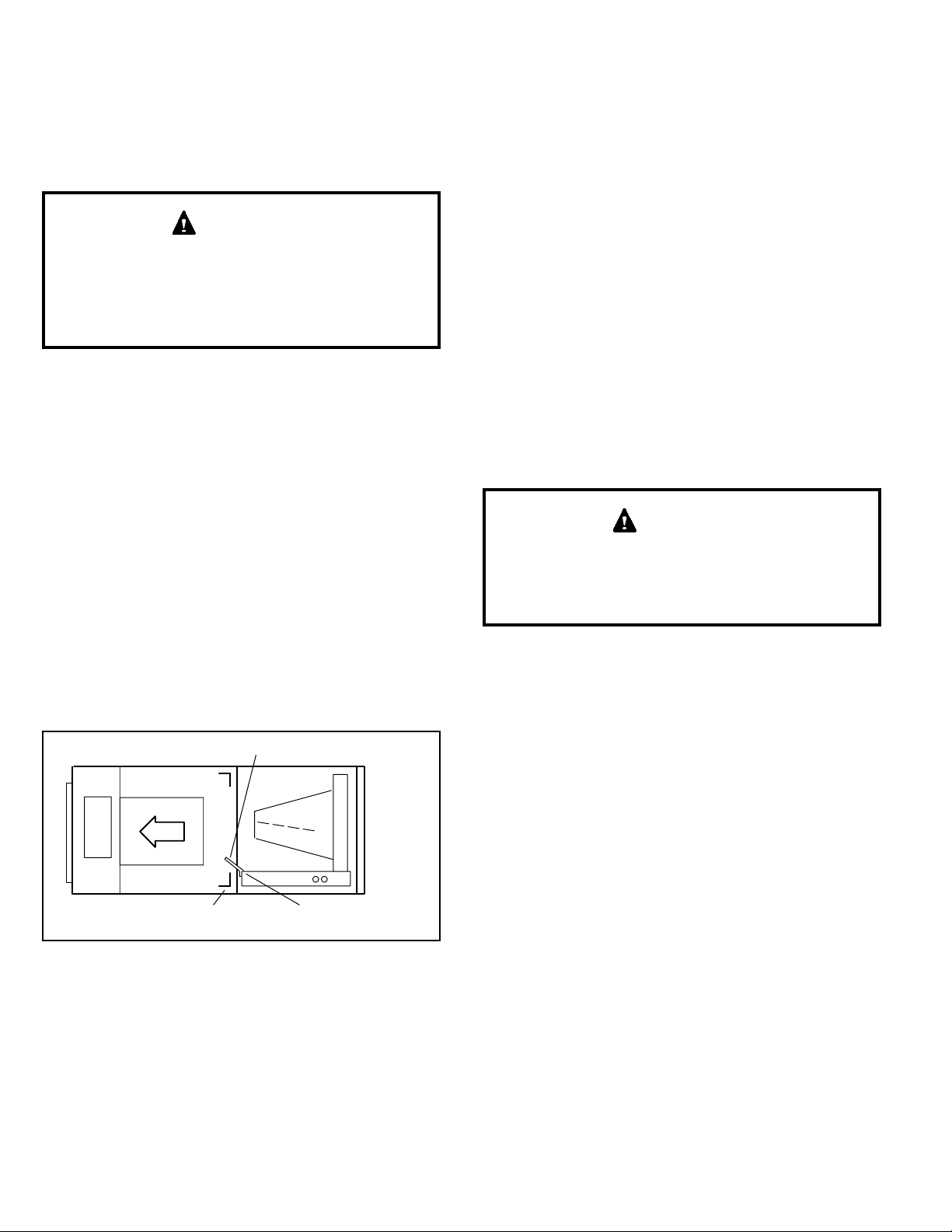
HORIZONTAL DRIP SHIELD (BCE7S60 MODEL)
DOWN-FLOW RAIL FRONT EDGE OF HORIZONTAL
DRAIN PAN
Figure 5. Left-Hand Discharge Conguration
8. Install the horizontal shield (BCE7S60 model) on the
front edge of the horizontal drain pan as illustrated in
Figure 5.
NOTE: For horizontal applications in high humidity
areas, remove the downow rail closest to the drain
pan. To remove rail, remove screw from rail at back
of unit and at cabinet support rail. Remove downow
rail then replace screws. Also, seal around the exiting
drain pipe, liquid and suction lines to prevent inltration
of humid air.
9. Knock out drain seal plate from access door. Secure
plate to cabinet front ange with screw provided.
10. Flip access door and replace it on the unit.
11. Set unit so that it is sloped 1/4ʺ toward the drain pan
end of the unit. Connect return and supply air plenums
as required using sheet metal screws.
12. If suspending the unit, it must be supported along the
entire length of the cabinet. If using chain or strap,
use a piece of angle iron or sheet metal attached to
the unit (either above or below) so that the full length
of the cabinet is supported. Use securing screws no
longer than 1/2ʺ to avoid damage to coil or lter, as
illustrated in Figure 3. Connect return and supply air
plenums as required using sheet metal screws.
Downow Application
Use the following procedures to congure the unit for
downow operations:
If electric heat sections with circuit breakers is applied
to downow BCE7S unit, the circuit breakers must
be rotated 180° to the UP position. See electric heat
installation instructions for more details.
IMPORTANT
Table 3 outlines the sizes of the various drip shields.
NOTE: (BCE7S60 Model Only) Remove access panels
and horizontal drip shield from the corrugated padding
between the blower and coil assembly.
1. Remove the coil assembly from the unit.
2. For best efciency and air ow, remove the horizontal
drain pan from the units in downow positions as
illustrated in Figure 6.
3. Rotate cabinet 180º from the upright position. See
Figure 6. You may need to rst remove the blower
assembly to lighten the cabinet for lifting.
4. Foam tape that is provided creates a seal between the
drip shield and the coil so that water does not leak into
the air stream. The foam tape pieces are precut. Apply
the tape to the drip shields as illustrated in Figure 7
and specied as follows:
• Apply two pieces of foam tape provided down both
ends of each shield. The tape should measure
4-3/4ʺ X 2ʺ (120 X 25 mm). Ensure that the tape
covers both sides of the shield equally.
• Apply the longer piece of 1 inch wide foam tape
between the end pieces of tape.
5. From the underside of the coil, install the downow
drip shield rmly in place as illustrated in Figure 8.

507746-01 Issue 1821 Page 9 of 39
Units Length Width
24 Not Required Not Required
30 15-7/8ʺ 4-11/16ʺ
36, 42 17-7/8ʺ 4-11/16ʺ
48, 60 19-7/8ʺ 4-11/16ʺ
Table 3. Downow Drip Shields (Tape Required)
HORIZONTA L DRAIN PAN
(REMOVE FROM UNIT)
UP-LOAD /
DOWNFLOW
DRAIN PAN
Figure 6. Downow Discharge Position
SIDE
VIEW
2” WIDE FOAM TA PE
DRIP SHIELD
1” WIDE FOAM TA PE (LONGER PIECE)
Figure 7. Applying Foam Tape to Drip Shield
COIL DRIP SHIELD
DRIP PAN
Figure 8. Downow Drip Shields
6. Replace the coil assembly and blower if you have
removed it. Replace the coil access panel.
7. Set the unit so that it is level. Using sheet metal screws,
connect the return and supply air plenums as required.
NOTE: For downow application, metal or Class I
supply and return air plenums must be used.
COMBUSTIBLE FLOOR
ADDITIVE BASE
PROPERLY SIZED
FLOOR OPENING
AIR
HANDER
UNIT
Figure 9. Downow Combustible Flooring Base
8. For downow installation on combustible ooring, an
additive base must be used as illustrated in Figure
9. Downow combustible ooring base kit 44K15 is
available for all units.
9. Cut an opening appropriately sized for combustible
base. Base dimensions are illustrated in Figure 10.
After opening has been cut, set the additive base into
opening. Connect outlet air plenum to the additive
base. Set the unit on the additive base so anges of
the unit drop into the base opening and seal against
the insulation strips. The unit is now locked in place.
Install return air plenum and secure with sheet metal
screws.
TOP VIEW
OPENING
1‐5/8 (41)
SIDE VIEW
1‐5/8 (41)
11‐3/8
(289)
2 (51)
1‐5/8 (41)
24 (610) BCE7S60 ONLY
22‐1/8 (562) OTHER MODELS
5/8 (16)
13‐3/8 (340)
SUPPLY AIR OPENING
BCE7S24 08-1/4 (464)
BCE7S30 AND UP 23-1/4 (591)
BCE7S24
15 (381)
BCE7S30 AND
UP 20 (508)
Figure 10. Downow Combustible Base Dimensions -
in. (mm)

507746-01Issue 1821Page 10 of 39
Brazing Connections
Polyolester (POE) oils used with HFC-410A refrigerant
absorb moisture very quickly. It is very important that the
refrigerant system be kept closed as much as possible.
DO NOT remove line set caps or service valve stub
caps until you are ready to make connections.
WARNING
Danger of re. Bleeding the refrigerant
charge from only the high side may
result in pressurization of the low side
shell and suction tubing. Application
of a brazing torch to a pressurized
system may result in ignition of the
refrigerant and oil mixture. Check the
high and low pressures before
applying heat.
WARNING
Danger of explosion!
Can cause equipment damage, injury, or
death.
When using a high pressure gas such as
nitrogen to pressurize a refrigeration or
air conditioning system, use a regulator
that can control the pressure down to 1
or 2 psig (6.9 to 13.8 kPa).
WARNING
Brazing alloys and ux contain materials which are
hazardous to your health.
Avoid breathing vapors or fumes from brazing
operations. Perform operations only in well ventilated
areas.
Wear gloves and protective goggles or face shield to
protect against burns.
Wash hands with soap and water after handling brazing
alloys and ux.
CAUTION
To prevent the build-up of high levels of nitrogen when
purging, it must be done in a well-ventilated area.
Purge low-pressure nitrogen (1 to 2 psig) through
the refrigerant piping during brazing. This will help to
prevent oxidation and the introduction of moisture into
the system.
IMPORTANT
Model Liquid
Line
Vapor
Line L15 Line Sets
24 3/8ʺ
(10mm)
5/8ʺ
(16mm) L15 line set sizes are
dependent on unit
match-up. See Product
Specications for outdoor
unit to determine correct
line set sizes
30, 36 3/8ʺ
(10mm)
3/4ʺ
(19mm)
42, 48 3/8ʺ
(10mm)
7/8"
(22mm)
60 3/8ʺ
(10mm)
7/8"
(22mm) Field fabricated
NOTE - Some applications may require a eld-provided 7/8ʺ
to 1-1/8ʺ adapter.
Table 4. Refrigerant Connections and Line Set
Requirements
Refrigerant lines must be connected by a qualied
technician in accordance with established procedures.
Refrigerant lines must be clean, dehydrated, refrigerant-
grade copper lines. Air handler coils should be installed
only with specied line sizes for approved system
combinations.
Handle refrigerant lines gently during installation. Sharp
bends or kinking in the lines will cause a restriction.
Do not remove sealing caps from the refrigerant piping
or unit connection points until connections are ready to
be completed.
IMPORTANT

507746-01 Issue 1821 Page 11 of 39
REMOVE ACCESS PANEL
A
REMOVE RUBBER PLUG FROM BOTH LIQUID
AND SUCTION LINES
B
USE A WET RAG TO PROTECT CTXV
SENSING BULB WHEN BRAZING
SUCTION LINE CONNECTIONS.
C
NITROGEN
HIGH
LOW
EITHER REMOVE OR PUSH PIPE WRAPPING BACK
THROUGH HOLE IN PIPING PLATE BEFORE LINE
SET CONNECTION AND BRAZING.
D
ECONNECT PIPES
FCONNECT GAUGES AND
START NITROGEN FLOW
GPLACE A WET RAG AGAINST PIPING
PLATE AND AROUND THE SUCTION
LINE CONNECTION. A
HBRAZE CONNECTION. ALLOW PIPE TO
COOL BEFORE REMOVING WET RAG
FROM CTXV SENSING BULB AND PIPING
PANEL AREA.
IREPEAT PREVIOUS PROCEDURE FOR LIQUID
LINE.
NOTE — REFER TO OUTDOOR UNIT INSTALLATION INSTRUCTIONS
FOR REFRIGERANT PIPING SIZE REQUIREMENTS.
NOTE — REFRIGERANT LINE SETS
SHOULD BE ROUTED TO ALLOW
FILTER ACCESSIBILITY.
NOTE — BCE7S SERIES UNITS USE NITROGEN OR DRY AIR
AS A HOLDING CHARGE. IF THERE IS NO PRESSURE WHEN
THE RUBBER PLUGS ARE REMOVED, CHECK THE COIL FOR
LEAKS BEFORE INSTALLING.
REFER TO INSTRUCTIONS PROVIDED WITH OUTDOOR UNIT FOR
LEAK TESTING, EVACUAT ING AND CHARGING PROCEDURES
FLOW REGULATED NITROGEN (AT 1 TO 2 PSIG)
THROUGH THE REFRIGERATION GAUGE SET INTO THE
VALVE STEM PORT CONNECTION ON THE OUTDOOR
UNIT LIQUID LINE SERVICE VALVE AND OUT OF THE
VALVE STEM PORT CONNECTION ON THE SUCTION
SERVICE VALVE.
PIPING
PLATE
NOTE - Use silver alloy brazing rods with five or six percent
minimum silver alloy for copper-to-copper brazing, 45
percent alloy for copper-to-brass and copper-to-steel
brazing.
PLEASE READ IMPORTANT ISSUES CONCERNING BRAZING
OPERATIONS ON PAGE 10 BEFORE PROCEEDING.
Figure 11. Brazing Connections

507746-01Issue 1821Page 12 of 39
Condensate Drain
After removal of drain pan plug(s), check drain hole(s)
to verify that drain opening is fully open and free of any
debris. Also check to make sure that no debris has
fallen into the drain pan during installation that may plug
up the drain opening.
IMPORTANT
Main Drain
Connect the main drain and route downward to drain line
or sump. Do not connect drain to a closed waste system.
See Figure 13 for typical drain trap conguration.
Overow Drain
It is recommended that the overow drain is connected to
an overow drain line for all units. If overow drain is not
connected, it must be plugged with provided cap.
For downow orientation, the overow drain MUST be
connected and routed to a overow drain line. See Figure
ABOVE
FINISHED
SPACE?
OVERFLOW DRAIN LINE
ALWAYS RUN AN OVERFLOW DRAIN LINE. IF NOT POSSIBLE TO
ROUTE OVERFLOW DRAIN LINE, INSTALL LOW VOLTAGE
OVERFLOW SWITCH KIT. WIRE KIT TO SHUT DOWN
COMPRESSOR PER INSTRUCTIONS.
NO
YES
CAT. NO.
X3169 CLEAN OUT
VENT
PRESS IN
(DO NOT GLUE)
VENT MUST EXTEND
ABOVE HEIGHT OF
COIL DRAIN PAN BY
TWO INCHES (51MM)
1” X 3/4” X 3/4”
REDUCING
TEE WITH
PLUG
P-TRAP149P66,
J-TRAP 91P90 OR
ANY PVC SCH 40
¾” P- OR J-TRAP
OVERFLOW
DRAIN
AIR HANDLER DRAIN PAN
WHEN A COIL IS LOCATED ABOVE A FINISHED SPACE, A
3/4” (19.1MM) SECONDARY DRAIN LINE MUST BE:
CONNECTED TO SECONDARY DRAIN PAN
OR
CONNECTED TO THE OVERFLOW DRAIN OUTLET OF
THE AIR HANDLER DRAIN PAN.
TRAPS MUST BE DEEP ENOUGH TO OFFSET MAXIMUM STATIC DIFFERENCES —
GENERALLY, TWO INCHES (51MM).
DRAIN LINE SHOULD
SLOPE A MINIMUM OF
ONE INCH PER 10
FEET (25MM PER 3
METERS)
NOTE — WHEN A AIR HANDLER IS LOCATED
ABOVE A FINISHED SPACE THE SECONDARY
DRAIN PAN MUST HAVE A LARGER FOOTPRINT
THAN THE AIR HANDLER.
MAIN
DRAIN
TO APPROVED
DRAIN
FOR NEGATIVE PRESSURE COILS (BLOWER
AFTER COIL) TRAPS ARE REQUIRED ON ALL
DRAIN LINES CONNECTED TO COIL.
COMPACT OVERFLOW SWITCH WITH 3/4” FEMALE SLIP INLET
AND MALE ADAPTER, TWO PART DESIGN FOR USE WHERE
OBSTRUCTIONS PREVENT DIRECT THREADING
SECONDARY
DRAIN PAN
2”
(51MM)
TRAP DEPTH
1P-TRAP 49P66 REQUIRES A LARGER INSTALLATION SPACE THAN THE J-TRAP 91P90.
2PIPE NIPPLE PROVIDED IN BAG ASSEMBLY - SCH 80, 3/4” I. D. X 5” - 34K7401 (1): CUT THE PIPE IN HALF AND USE IT TO ROUTE THE MA IN DRAIN.
MAIN
DRAIN
PROVIDED
PIPE NIPPLE 2
CUT TO
REQUIRED
LENGTH
SIDE VIEW
Figure 13. Typical Main and Overow Drain Installations
12 for main and overow drain locations based on coil
orientation.
LEFT-HAND AIR
DISCHARGE
MAIN DRAIN ON
RIGHT
OVERFLOW
DRAIN ON LEFT
UP-FLOW OR
DOWN-FLOW
RIGHT-HAND AIR
DISCHARGE
Figure 12. Main and Overow Drain Locations Based
on Coil Orientation
Best Practices
The following best practices are recommended for the
condensate removal process:
• Main and overow drain lines should NOT be smaller
than both drain connections at drain pan.
• Overow drain line should run to an area where
homeowner will notice drainage.

507746-01 Issue 1821 Page 13 of 39
• It is recommended that the overow drain line be
vented and a trap installed. Refer to local codes.
• Condensate drain lines must be congured or provided
with a cleanout to permit the clearing of blockages and
for maintenance without requiring the drain line to be
cut.
Inspecting and Replacing Filters
Filter access door must be in place during unit operation.
Excessive warm air entering the unit from unconditioned
space may result in water blow-off problems.
IMPORTANT
Filters may be duct-mounted or installed in the cabinet. A
lter is installed at the factory. Note that lter access door
ts over access panel. Air will leak if the access panel is
placed over the lter door.
Filters should be inspected monthly and must be cleaned
or replaced when dirty to assure proper furnace operation.
To replace lter:
1. Loosen the thumbscrews holding the lter panel in
place.
2. Slide the lter out of the guides on either side of
cabinet.
3. Insert new lter.
4. Replace panel.
See Table 5 for replacement lter sizes.
BCE7S Filter Size – in. (mm)
24, 30, 36 20 x 20 x 1 (508 x 508 x 25)
42, 48, 60 20 x 24 x 1 (508 x 610 x 25)
Table 5. Filter Dimensions
Sealing the Unit
There must be an airtight seal between the bottom of
the air handler and the return air plenum. Use berglass
sealing strips, caulking, or equivalent sealing method
between the plenum and the air handler cabinet to
ensure a tight seal. Return air must not be drawn from a
room where this air handler or any gas-fueled appliance
(i.e., water heater), or carbon monoxide-producing
device (i.e., wood replace) is installed.
WARNING
Seal the unit so that warm air is not allowed into the cabinet.
Warm air introduces moisture, which results in water blow-
off problems. This is especially important when the unit is
installed in an unconditioned area.
Make sure the liquid line and suction line entry points are
sealed with either the provided exible elastomeric thermal
insulation, or eld provided material (e.g. Armaex,
Permagum or equivalent). Any of the previously mentioned
materials may be used to seal around the main and
auxiliary drains, and around open areas of electrical inlets.
Field Control Wiring
Wiring must conform to the current National Electric Code
ANSI/NFPA No. 70, or Canadian Electric Code Part I, CSA
Standard C22.1, and local building codes. Refer to following
wiring diagrams. See unit nameplate for minimum circuit
ampacity and maximum over-current protection size.
Electric Shock Hazard.
Can cause injury or death.
Foil-faced insulation has conductive characteristics
similar to metal. Be sure there are no electrical
connections within a ½ʺ of the insulation. If the foil-faced
insulation comes in contact with electrical voltage, the
foil could provide a path for current to pass through to
the outer metal cabinet. While the current produced
may not be enough to trip existing electrical safety
devices (e.g. fuses or circuit breakers), the current can
be enough to cause an electric shock hazard that could
cause personal injury or death.
WARNING
Run 24V Class II wiring only through specied low
voltage opening. Run line voltage wiring only through
specied high voltage opening. Do not combine voltage
in one opening.
WARNING
Select the proper supply circuit conductors in accordance
with tables 310-16 and 310-17 in the National Electric
Code, ANSI/NFPA No. 70 or tables 1 through 4 in the
Canadian Electric Code, Part I, CSA Standard C22.1.
Separate openings have been provided for 24V low
voltage and line voltage. Refer to the dimension illustration
of specic location.
Use copper conductors only.
CAUTION

507746-01Issue 1821Page 14 of 39
Figure 14. BCE7S Air Handler Unit Typical Wiring Diagram

507746-01 Issue 1821 Page 15 of 39
AIR HANDLER CONTROL COMES FROM FACTORY WITH A
METAL JUMPERS BETWEEN W1 TO W2 AND W2 TO W3. SEE
FIGURE 22 FOR HEAT SECTION CONFIGURATION.
CUT ON-BOARD LINK R-DS WHEN DEHUMIDIFICATION TERMINAL IS USED.
BCE7SCOMFORT SYNC™
A
IR
CONDITIONER
UNIT
(TWO-STAGE)
RED
BROWN
YELLOW
BLUE
BLACK
1
1
R
W3
W2
W1
O
Y1
Y2
G
DS
C
R
H
W2
W1
O
L
Y1
Y2
G
D
B
C
Y1-Y2
2-STAGE
COMPR
R-O
HEAT
PUMP
R-DS
DEHUM
OR
HARMONY
CUT FOR OPTION
CUT ON-BOARD LINK Y1-Y2 FOR TWO-STAGE AC
DO NOT CUT ON-BOARD LINK R -O.
IMPORTANT — USE CARE WHEN CUTTING
ON-BOARD LINKS TO PREVENT DAMAGE TO
CONTROL. SEE FIGURE 19, BCE7S JUMPER AND
LINK GUIDE, FOR FURTHER DETAILS.
AIR HANDLER
CONTROL
Figure 15. Control (Field Wiring) – Cooling Application (Non-Communicating)
HEAT PUMP
UNIT
(TWO-STAGE) X2658 OUTDOOR SENSOR IS REQUIRED FOR OUTDOOR
TEMPERAT URE DISPLAY, DEW POINT CONTROL, HEAT
PUMP AND DUAL FUEL BALANCE POINTS.
RRR
W3 H
W2
W2
W1 W1 W1
O
OO
L
L
Y1
Y1
Y1
Y2Y2
G
G
CCC
T
T
D
B
Y2
DS
O. D.
SENSOR
(X2658)
Y2
OUT
BL
1
1
CUT ON-BOARD LINK R -O.
CUT ON-BOARD LINK R-DS WHEN DEHUMIDIFICATION TERMINAL IS USED.
CUT ON-BOARD LINK Y1-Y2 FOR TWO-STAGE HP
2
2
FIELD PROVIDED JUMPER BETWEEN Y2 OUT BL ON
HEAT PUMP TO Y2 ON BCE4MS.
Y1-Y2
2-STAGE
COMPR
R-O
HEAT
PUMP
R-DS
DEHUM
OR
HARMONY
CUT FOR OPTION
BCE7S
IMPORTANT — USE CARE WHEN CUTTING
ON-BOARD LINKS TO PREVENT DAMAGE TO
CONTROL. SEE FIGURE 19, BCE7S JUMPER AND
LINK GUIDE, FOR FURTHER DETAILS.
COMFORT SYNC™
Figure 16. Control (Field Wiring) – Heat Pump (Non-Communicating)
ELECTROSTATIC DISCHARGE (ESD)
Precautions and Procedures
Electrostatic discharge can affect electronic components. Take care during unit installation and service to protect the
unit’s electronic controls. Precautions will help to avoid control exposure to electrostatic discharge by putting the unit,
the control and the technician at the same electrostatic potential. Touch hand and all tools on an unpainted unit surface
before performing any service procedure to neutralize electrostatic charge.
WARNING

507746-01Issue 1821Page 16 of 39
RED
YEL
BLU
BLK
BRN
COMFORT SYNC
THERMOSTAT
OUTDOOR UNIT
PUR
OUTDOOR
SENSOR
(X2658)
BLK
RED
BLK
PUR
EDA UNIT
FAN
RELAY
NOTES -
/1\ NOT REQUIRED WITH SINGLE‐SPEED OUTDOOR FAN.
/2\ NOT REQUIRED FOR SINGLE-STAGE OPERATION.
/3\
T
T
D
DO NOT CUT ON-BOARD LINK R -O.
CUT ON-BOARD LINK R-DS WHEN DEHUMIDIFICATION
TERMINAL IS USED.
CUT ON-BOARD LINK Y1-Y2 FOR TWO-
STAGE A/C
AIR HANDLER CONTROL INCLUDES FACTORY-INSTALLED
JUMPERS BETWEEN W1 AND W2 AND BETWEEN W2 AND W3.
SEE FIGURE 22 FOR HEAT SECTION CONFIGURATION.
Y1-Y2
2-STAGE
COMPR
R-O
HEAT
PUMP
R-DS
DEHUM
OR
HARMONY
CUT FOR OPTION
BCE7S
IMPORTANT — USE CARE WHEN CUTTING
ON-BOARD LINKS TO PREVENT DAMAGE TO
CONTROL. SEE FIGURE 19, BCE7S JUMPER AND
LINK GUIDE, FOR FURTHER DETAILS.
Figure 17. Control (Field Wiring) — Cooling Application (Humidication Control and Second-Stage Outdoor Fan
Relay Wiring) Non-Communicating
Figure 18. Control (Field Wiring) — Heat Pump Application (Humidication Control and Second-Stage Outdoor
Fan Relay Wiring) Non-Communicating
YELLOW
BLUE (NOT REQUIRED FOR SINGLE STAGE)
RED
BLACK
PURPLE
PURPLE
BLACK
BLUE
RED
FAN RELAY (NOT REQUIRED
WITH SINGLE−SPEED
OUTDOOR FAN)
OUTDOOR
SENSOR
(X2658)
COMFORT SYNC
THERMOSTAT
BCE7S
OUTDOOR UNIT
CUT ON-BOARD LINK R -O.
CUT ON-BOARD LINK Y1-Y2 FOR TWO-STAGE A/C ONLY
CUT ON-BOARD LINK R-DS WHEN DEHUMIDIFICATION
TERMINAL IS USED.
T
T
Y1-Y2
2-STAGE
COMPR
R-O
HEAT
PUMP
R-DS
DEHUM
OR
HARMONY
CUT FOR OPTION
IMPORTANT — USE CARE WHEN CUTTING
ON-BOARD LINKS TO PREVENT DAMAGE TO
CONTROL. SEE FIGURE 19, BCE7S JUMPER AND
LINK GUIDE, FOR FURTHER DETAILS.

507746-01 Issue 1821 Page 17 of 39
Sensor Connections and Wiring Requirements
Outdoor Air Sensor
This is a two screw terminal for connection to an X2658
outdoor temperature sensor. The Control takes no
action on the sensor status other than to communicate
the temperature to the RSBus network. Wiring distance
between the AHC and outdoor temperature sensor should
not exceed 200 feet when wired with 18-gauge thermostat
wire.
• Minimum temperature: -40ºF (-40ºC)
• Maximum temperature: 70ºF (158ºC)
Air Handler Control 9-Pin Connector (P8)
1. Air Handler (no electric heat) – Two wire factory
harness (wired to pins 7 and 8) which provides 230
VAC power to Air Handler Control.
2. Air Handler (with electric heat) – Eight wire factory
harness (all pin position are wired as noted in Table 6).
Position Function / Description
1 Heat stage 1 relay coil
2 Heat stage 2 relay coil
3 Relay coil return
4 Not used
5 Not used
6 Not used
7 L1 230VAC supply from heater kit
8 L2 230VAC supply from heater kit
9 Not used
Table 6. Electric Heat Connection (P8)
Control Connections and Wiring Requirements
This section provides information on communicating and
non-communicating control connections and wire run
lengths.
Label Label Function
Thermostat
R24VAC
i+ RSbus data high connection
i- RSbus data low connection
C24VAC command (ground)
Outdoor Unit
R24VAC
i+ RSbus data high connection
i- RSbus data low connection
C24VAC command (ground)
Link i+ Not used
i-
Table 7. Air Handler Control Connections –
Communicating
Wire Run Length AWG # Insulation / Core Types
Maximum length
or wiring for all
connections on the
RSbus is limited to
1500 feet (457 meters)
18
Color-coded,
temperature rating 95°F
(35°C) minimum, solid
core. (Class II Rated
Wiring)
Table 8. Run Length – Communicating
Wire Run Length AWG # Insulation / Core Types
Less than 100’ (30m) 18 Color-coded,
temperature rating 95°F
(35°C) minimum, solid
core. (Class II Rated
Wiring)
More than 100’ (30m) 16
Table 9. Run Length – Non-Communicating
Wiring Connections
1. Install line voltage power supply to unit from a properly
installed circuit breaker.
2. Ground unit at unit disconnect switch or to an earth
ground.
NOTE: Connect conduit to the unit using a proper
conduit tting. Units are approved for use only with
copper conductors. A complete unit wiring diagram is
located on the back side of the unit’s access panel.
3. Install low voltage wiring from outdoor to indoor unit
and from thermostat to indoor unit.

507746-01Issue 1821Page 18 of 39
Table 10. Air Handler Control Connections
Indoor Control
Terminal Label
Function
Non-Communicating Room Thermostat
(Indoor and Outdoor -24 volts)
Indoor Communicating Outdoor Non-
Communicating
Full Communication
(Indoor & Outdoor)
W1 (Input) Indicates a rst-stage heating demand. This
input is an anticipator for the thermostat. N/A N/A
W2 (Input)
Indicates a second-stage h eating demand.
W1 input must be active to recognize
second-stage heat demand.
N/A N/A
W3 (Input)
Indicates a third-stage heating demand. W1
and W2 inputs must be active to recognize
third-stage heat demand.
N/A N/A
Y1 & Y2 (Input/
Output)
Room thermostat inputs 24 volts to the Y1
and Y2 terminals on the indoor control.
The 24 volt signal is then passed through
to the outdoor unit. During a second-stage
demand, both Y1 and Y2 are active. The Y1
terminal is connected to Y2 by link (Solid
jumper on control that would be cut for 2
stage applications).
The room thermostat communicated
with the indoor control. The indoor
control outputs 24 volts on i ts Y1 and
Y2 terminals which are hard wired to the
non-communicating outdoor unit.
In a full communicating
system, no wiring is
required on Y1 and Y2
terminals.
G (Input) Indicates a 24 volt indoor blower demand.
In a communicating system, ”G” input to indoor control is used by
non-communicating IAQ devices (such as LVCS, HRV or ERV) to
ensure indoor blower demand.
CThe C terminal shall interconnect the signal ground of the room thermostat with secondary transformer ground (TR)
and chassis ground (GND).
R The R terminal shall be capable of providing the power to the thermostat and all the associated loads.
O (Input/
Output)
Room thermostat inputs 24 volts to the
O terminal on the indoor control. The O
terminal is connected to R by link (Solid
jumper on control that would be cut if unit
was a heat pump).
The room thermostat communicated with
the indoor control. The indoor control
outputs 24 volts on its O terminals which
are hard wired to the non-communicating
outdoor unit. If there is 24 volts on O, the
reversing valve will be energized and the
outdoor unit will run in the cooling mode.
If O does not have 24 volts, the outdoor
unit will run in heating mode.
In a full communicating
system, O terminal is
not wired.
DS (Input)
Used for Harmony III zoning systems, or
thermostat with dehumidication capability.
The DS terminal is connected to R by link
(Solid jumper on control that would be cut if
for the above applications).
Harmony III control - This will allow the
control to vary the voltage signal to the
indoor b lower motor to control required
CFM.
Dehumidication - Allow a 24 volt
signal on the DS to turn off and on the
dehumidication mode.
N/A N/A
DH (Output) The DH terminal provides a 24VAC output for dehumidication needs in communicating systems.
H (Output) The H terminal provides a 24VAC output for humidication needs in both communicating and non-communicating
mode.

507746-01 Issue 1821 Page 19 of 39
OUTDOOR
AIR SENSOR
HEAT
1234
COOL
1234
DELAY
1234
ADJUST
NORM + -
HUMIDIFICATION
SMARTAUTO
EVENHEAT
1234
BLOWER
ONLY CFM
100
115
130
85
Y1-Y2
2-STAGE
COMPR
R-O
HEAT
PUMP
R-DS
DEHUMOR
C
W1
W2
G
Y2
Y1
C
R
DH
H
L
O
DS
W3
FACTORY
JUMPER
FUSE 3 AMP
XFMR24V
24 VAC
COM
3
6
9
1
4
7
XFMR LINE
G
7-SEGMENT LED
HUMIDIFICATION
CONTROL LINK
(JUMPERS R to DS)
HEAT PUMP LINK
(JUMPERS R to O)
2-STAGE
COMPRESSOR LINK
(JUMPERS Y1 to Y2)
ON-BOARD LINK
OPTION SELECTION
1
JUMPER & LINK GUIDE
CUT ON-BOARD LINK (SOLDER TRACE) COMPLETELY
THROUGH BOTH LAYERS ON THE CONTROL BOARD
1
COOLING BLOWER RAMPING
DELAYPROFILE #3
OFF-82%-100%-OFF
CLG
HP
DELAYPROFILE #2
DELAYPROFILE #1
OFF-100%-OFF
DELAYPROFILE #4
OFF-50%-82%-
100%-50%-OFF
*
(COOLING MODE UNLESS NOTED)
1234
1234
1234
1234
*
HUMIDIFICATION MODE
SMART MODE
- ”H” ENABLED WHEN
HEAT ACTIVE
(HP or ELECT. HT)
AUTO MODE
- ”H” ENABLED WHEN
BLOWER ACTIVE
& NO CLG
OR DEHUM
HUMIDIFICATION MODE
24VAC OUTPUT ON ”H”
FOR HUMIDIFIER OR
ACCESSORY INTERLOCK
SMART AUTO
SMART AUTO
COOLING MODE
BLOWER SPEED
HIGH
SPEED
MEDIUM-LOW
SPEED
LOW
SPEED
1234
MEDIUM-HIGH
SPEED
*
1234
1234
1234
(COOLING & HP MODE)
HEATING MODE
BLOWER SPEED
*
(ELECTRIC HT MODE)
1234
1234
1234
1234
LOW
SPEED
MEDIUM-LOW
SPEED
MEDIUM-HIGH
SPEED
HIGH
SPEED
NORM +-
NORM+-
NORM +-
BLOWER
ADJUST SELECTION
NORMAL
(+ 10%)
SETTING
(-10%)
SETTING
*
PUSH
BUTTON
HIGH
SPEED
(100%)
MEDIUM-HIGH
SPEED
(70%)
LOW
SPEED
(28%)
* MEDIUM-LOW
SPEED
(38%)
1234
1234
1234
1234
CONTINUOUS FAN
BLOWER SPEED
IMPORTANT: USE CARE WHEN CUTTING LINKS TO
PREVENT DAMAGE TO CONTROL.
2
5
8
P8
L1L2
L2 L1 INDOOR
BLOWER
POWER
EARTH
INDOOR BLOWER
SIGNAL
456
12 3
OUTDOOR UNIT
LINK
I +I -
I +I-RC
I +I-
RC
THERMOSTAT
HUMIDITROL
DH
DISCHARGE
AIR SENSOR
HARMONY
R-DS
DEHUM
or
NO HUMIDIFICATION
DO NOT CUT
HUMIDIFICATION
CUT LINK
HARMONY
R-DS
DEHUM
or
HARMONY
1
A/C UNIT HEAT PUMP UNIT
R-0
HEAT
PUMP
R-0
HEAT
PUMP
1
DO NOT CUTCUT LINK
2 STAGE
COMPR
1-STG COMPRESSOR 2-STG COMPRESSOR
Y1-Y2
1
DO NOT CUT CUT LINK
*
*
*
2 STAGE
COMPR
Y1-Y2
* INDICATES FACTORY DEFAULT SETTING
CONTROL OR ZONINGCONTROL OR ZONING
Figure 19. Air Handler Conguration

507746-01Issue 1821Page 20 of 39
Air Handler Control Button, Display and
Jumpers
Use Figure 19 as reference for jumper settings. If any of the
referenced jumpers are missing, the Air Handler Control
will display Error Code 130 as per Table 13, and the Air
Handler Control will automatically use the factory default
setting show in Figure 19.
Before changing any clippable links or jumper settings,
make sure the motor has completely stopped. Any
changes will not take place while the motor is running.
IMPORTANT
Push Button
An on-board push button is provided for the purpose of
placing the air handler control in different operation modes
and can be used to recall stored error codes. When button
is pushed and held, air handler control will cycle through
a menu of options depending on current operating mode.
Every three seconds a new menu item will be displayed.
If the button is released while that item is shown on the
display, air handler control will enter displayed operating
mode, or execute dened operation sequence for that
menu option. Once all items on menu have been displayed
the menu resumes from the beginning (if button is still
held).
1. Press the diagnostic push button and hold it to cycle
through a menu of options. Every three seconds a new
menu item will be displayed. Release the button when
the desired mode is displayed.
2. When the solid “E” is displayed, the control enters
the Error Code Recall mode. Error Code Recall mode
menu options: No change (displaying error history)
remains in Error Code Recall mode; solid “≡” exits
Error Code Recall mode; and solid “c” clears the
error history. Must press button while ashing “c” is
displayed to clear error codes.
3. When the solid “-” is displayed, the control enters
the applicable mode. Field conguration mode menu
options: Solid “C” starts pressure switch calibration;
blinking “-” exits current active mode.
Jumpers
Jumpers are used for non-communicating mode only.
1. Humidication — Controls the status of H terminal
on the thermostat block. Congurations are as follows:
• If jumper is installed in SMART Humidication
position (Default), H terminal is active if heat
demand is present and indoor blower is running.
• If jumper is installed in AUTO Humidication
position, H terminal is energized whenever indoor
blower is running.
2. Blower Only CFM — Used to select Indoor blower
CFM for continuous operation.
3. Heat — Used to select Indoor blower CFM for electrical
heat by placing the jumper in proper position. Actual
CFM values for different air handler sizes are shown in
Targeted CFM tables starting on Page 25.
4. Cool — Used to select cooling indoor blower CFM
by placing the jumper in proper position. Actual CFM
values for different air handler sizes are shown in
Targeted CFM tables starting on Page 25.
5. Adjust - Used to select the indoor blower CFM
adjustment value by placing the jumper in appropriate
position.
• If NORM is selected, indoor blower runs at normal
speeds.
• If + is selected, indoor blower runs at approximately
10% higher speed than NORM setting.
• If - is selected, indoor blower runs at approximately
10% lower speed than NORM setting.
If the jumper is missing, the Air Handler Control will
activate the Conguration Jumper is Missing alarm
and will automatically use the default factory setting
in Table 11. See Figure 19 for jumper congurations.
Actual CFM values for different air handler sizes are
shown in Targeted CFM tables starting on Page 25.
6. Delay — Indoor blower cooling prole, delay for
cooling and heat pump operations.
• For heat pump heating operation only delay
proles 1 and 2 are applicable. If proles 3 or 4
have been selected, heat pump operation will use
prole 1 only.
• For heat pump cooling operation all 4 proles are
operational.
If the jumper is missing, the Air Handler Control will
activate the Conguration Jumper is Missing alarm
and will automatically use the default factory setting
in Table 11. See Figure 19 for jumper congurations.
Delay Prole 1
A
B
OFFOFF
100%
CFM
COOLING
DEMAND
A. When cool or heat demand is initiated, motor ramps up
to 100% and runs at 100% until demand is satised.
B. Once demand is met, motor ramps down to stop.
Table of contents
Other Armstrong Air Air Handler manuals
Popular Air Handler manuals by other brands

ActronAir
ActronAir Cascade 2 Series owner's manual

Frico
Frico PA2500 Original instructions

York
York MAXA-MISER VR036A15H installation instructions

Remak
Remak AeroMaster FP Series Service instructions

Swegon
Swegon PARASOL Z VAV c Installation, commissioning maintenance

Domus Ventilation
Domus Ventilation D-DMEV installation instructions

RDZ
RDZ SR 2001 Installation and technical manual

Amana
Amana AMVE Installation & operating instructions

Pioneer
Pioneer DR024GHFE18HT2 installation manual

RDZ
RDZ WHR 62 Plus Installation & technical manual

Troges
Troges Airset Assembly, operation and maintenance instructions

ForestAir
ForestAir E-Tech Series installation manual