ARMTEL TOP-HS-IP2 User manual

TOP-HS-IP2
HANDSET UNIT
RMLT.465484.003UM
User Manual
Document version 7
26.30.23.000
2021

armtel.com
© Armtel info@armtel.com

TOP-HS-IP2 HANDSET UNIT
User Manual
armtel.com page 1/32
info@armtel.com © Armtel
INTRODUCTION
This user manual applies to «TOP-HS-IP2 Handset unit» RMLT.465484.003
manufactured by Armtel LLC, and is intended to familiarize the user with the device and
the procedure for its operation at the installation site.
Designed for organization of two-way communication as a component of IPN system
manufactured by Armtel LLC.
Short name of product – TOP-HS-IP2.
Maintenance personnel for TOP-HS-IP2 shall be appointed by the management at
the installation site.
The maintenance personnel shall be required to know the operating procedure of
TOP-HS-IP2 to the extent provided for by the user manual.
The maintenance personnel shall be required to know the operating procedure of
TOP-HS-IP2 to the extent provided for by the user manual.
Example of TOP-HS-IP2 designation during ordering and in documentation:
«TOP-HS-IP2 Handset unit» RMLT.465484.003
ATTENTION! In connection with systematic work to improve the design and
manufacturing technology, it is possible some discrepancy between the description and
the supplied product, which does not affect its operation or maintenance.

TOP-HS-IP2 HANDSET UNIT
User Manual
page 2/32 armtel.com
SAFETY PROVISIONS
During installation and operation observe the safety measures specified by local
codes and regulations on electrical safety.
TOP-HS-IP2 functions with the power supply of ultra-low 5V DC; no special safety
measures specified by local codes and regulations on electrical safety are required.
To avoid electric shock, do not:
−turning on the device with damaged power and interface cables or connectors.
ATTENTION! NEVER DISMANTLE THE PRODUCT CONNECTED TO MAINS.
Installation and connection of the product only in a de-energized state.
Do not use the product in rooms with high humidity (more than 80 %) or conductive
dust.
In order to ensure fire safety, follow the following rules:
−before connecting the product to the power supply, make sure the power and
communication cables are properly insulated;
−protect power and communication cables from damage.
The safety provisions for specific operations described in this manual are marked
with:

TOP-HS-IP2 HANDSET UNIT
User Manual
armtel.com page 3/32
info@armtel.com © Armtel
CONTENTS
INTRODUCTION.................................................................................................................................................................... 1
SAFETY PROVISIONS........................................................................................................................................................... 2
CONTENTS .............................................................................................................................................................................. 3
1 DESCRIPTION AND OPERATION................................................................................................................................. 5
1.1 Product description and operation .................................................................................................................. 5
1.1.1 Features ............................................................................................................................................................. 5
1.1.2 Main specifications........................................................................................................................................ 6
1.1.3 Operations conditions.................................................................................................................................. 7
1.1.4 Scope of supply .............................................................................................................................................. 8
1.1.5 Design................................................................................................................................................................. 9
1.1.6 Labeling ...........................................................................................................................................................11
1.1.7 Package............................................................................................................................................................12
1.2 Description and operation of the product components ........................................................................13
1.2.1 General information....................................................................................................................................13
1.2.2 Main board.....................................................................................................................................................13
1.2.3 Handset microphone..................................................................................................................................14
1.2.4 Handset speaker...........................................................................................................................................14
2 INTENDED USE ................................................................................................................................................................15
2.1 Operating limits .....................................................................................................................................................15
2.2 Preparation for use ...............................................................................................................................................15
2.3 Safety precautions.................................................................................................................................................16
2.4 Installation, connection and dismantling .....................................................................................................17
2.5 Operation .................................................................................................................................................................18
2.6 Troubleshooting ....................................................................................................................................................18
3 MAINTENANCE................................................................................................................................................................19
3.1 General guidelines ................................................................................................................................................19
3.2 Safety precautions.................................................................................................................................................19
3.3 Maintenance procedure......................................................................................................................................19
3.4 Checking operability ............................................................................................................................................20
4 PEPAIR ..............................................................................................................................................................................21
5 STORAGE............................................................................................................................................................................22
6 TRANSPORTATION.........................................................................................................................................................23
7 DISPOSAL...........................................................................................................................................................................24

TOP-HS-IP2 HANDSET UNIT
User Manual
page 4/32 armtel.com
APPENDIX A (reference) Connection......................................................................................................................25
APPENDIX B (reference) Desktop mounting complete with TOP-DIS-IP2 / TOP-PAD-IP2................26
APPENDIX C (reference) Recommendations for flush-mounting of TOP-HS-IP2 .................................29
TOP-HS-IP2 HANDSET UNIT
User Manual
armtel.com page 5/32
info@armtel.com © Armtel
1 DESCRIPTION AND OPERATION
1.1 Product description and operation
1.1.1 Features
TOP-HS-IP2 Handset unit is designed for enhancing the functionality of
TOP-DIS-IР2 Desktop call station RMLT.465311.009 and TOP-PAD-IP2 RMLT.465239.001
Desktop intercom station including digital intercom and Public Ad-dress/General Alarm
communication systems manufactured by Armtel LLC.
ТОР-HS-IP2 can be applied in distributed and centralized digital intercom and Public
Address /General Alarm communication systems (based on allotted SIP server
manufactured by Armtel LLC) at metal, chemical, oil-processing, oil and gas, energy and
transport industries or at facilities of the same type. ТОР-HS-IP2 is designed for installation
in control, office rooms and premises.
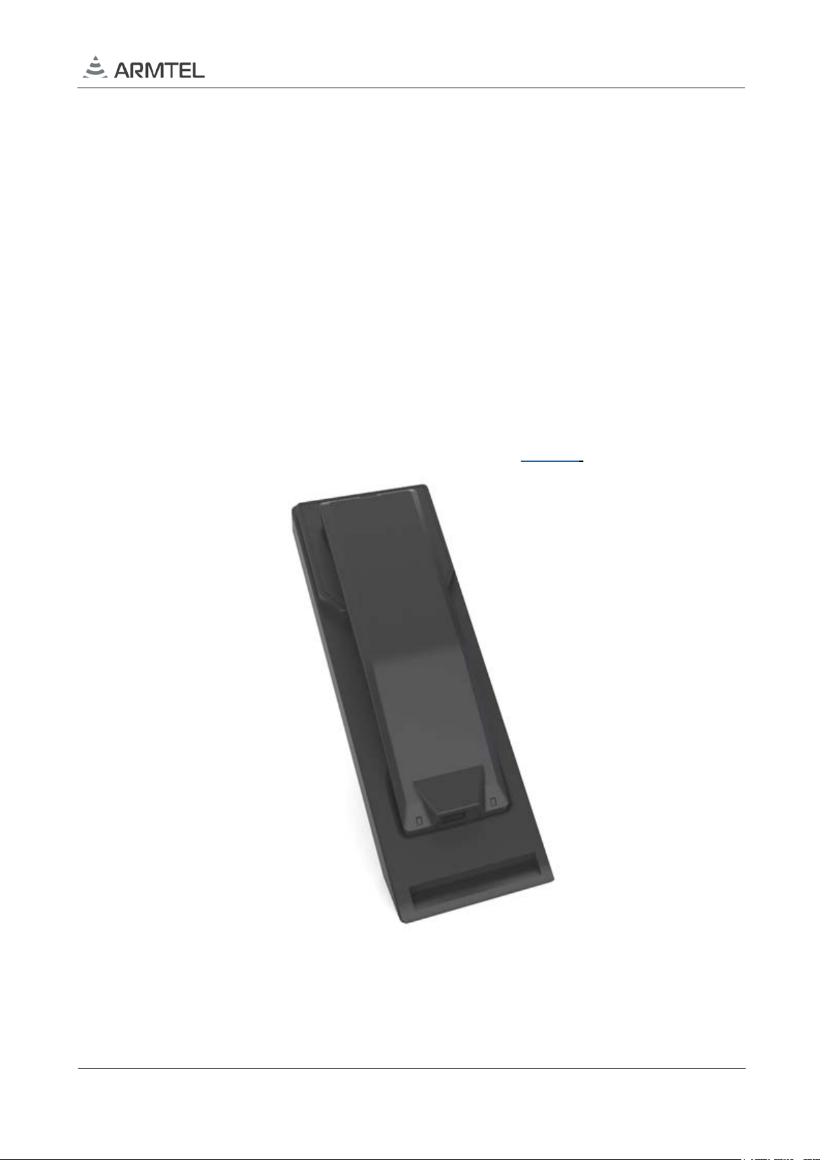
The external appearance of TOP-HS-IP2 is illustrated at Figure 1.
Figure 1 – External appearance of TOP-HS-IP2
TOP-HS-IP2 does not perform any functions without connecting to TOP-DIS-IР2 or
TOP-PAD-IP2.

TOP-HS-IP2 HANDSET UNIT
User Manual
page 6/32 armtel.com
TOP-HS-IP2 performs the following functions:
−Duplex communication for subscribers using TOP-DIS-IР2 Desktop call station
or TOP-PAD-IP2 Desktop intercom station connected to TOP-HS-IP2;
−switching the active sound path when lifting the handset from the base stand
to it;
−switching the active sound path to the built-in speaker and "Gooseneck"
microphone when installing the handset on the base stand.
Configuration of TOP-HS-IP2 shall be carried out using the personal computer of the
IPN network administrator on which IPN2 RU.RMLT.00041-01 IPN Config Tool software
configuration application is installed.
1.1.2 Main specifications
Main specifications and performance characteristics of TOP-HS-IP2 are given in
Table 1.
Table 1 – Main specifications and performance characteristics
Parameters Value
Rated voltage, V 5,0
Supply voltage range, V 4,75…5,25
Maximum current consumption, no more than, А0,02
Power consumption, no more than, W 0,1
Digital communication line with TOP-DIS-IP2 and TOP-PAD-IP2 I2C (Armtel)
Electrical safety class under GOST IEC 61140-2012 III
Weight, kg (0,7 ± 5 %)

TOP-HS-IP2 HANDSET UNIT
User Manual
armtel.com page 7/32
info@armtel.com © Armtel
1.1.3 Operations conditions
Environmental requirements for TOP-HS-IP2 in operating mode:
−ambient temperature range from 0 to +40 °C;
−relative humidity up to 80 % at 25 °C, at lower temperatures, without
condensing;
−atmospheric pressure within the range from 84 to 106,7kPa.
Note - The limiting low ambient temperature, after the effect of which, the normal
functioning of the product is guaranteed is minus 20 °C.
Ingress protection of TOP-HS-IP2 complies with IP42.
TOP-HS-IP2 complies with the requirements electromagnetic interference according
to IEC 61000-6-2:2005, with not lower B quality criterion. The electromagnetic interference
from TOP-HS-IP2 does not exceed the codes specified in IEC 61000-6-4:2006.
TOP-HS-IP2 HANDSET UNIT
User Manual
page 8/32 armtel.com
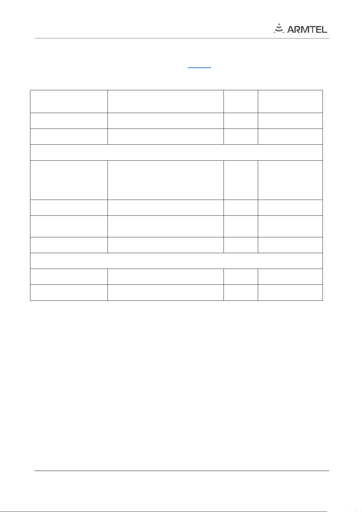
1.1.4 Scope of supply
Scope of supply of TOP-HS-IP2 is given in Table 2.
Table 2 – Scope of supply
Identification Name
Quanty-
ty, pcs.
Note
RMLT.465484.003
TOP-HS-IP2 Handset unit
1
RMLT.305636.002
Package
1
Product сomponents
RMLT.465931.001
HS mounting kit
(junction plates RMLT.741522.001 –
2 pcs., self-tapping plastic screws of
3х8 – 8 pcs.)
1
RMLT.469119.001
AUI cable EC-ТОР
1
RMLT.469119.002
Audio module cable
(4P4C analog path connection)
1
Handset stretch cord, 2,5 m
1
Operational documentation
RMLT.465484.003PP
Product Passport
1
RMLT.465484.003UM
User Manual
1
TOP-HS-IP2 HANDSET UNIT
User Manual
armtel.com page 9/32
info@armtel.com © Armtel
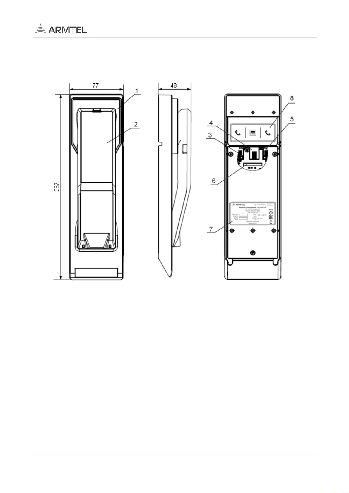
1.1.5 Design
1.1.5.1 The external appearance and overall dimensions of TOP-HS-IP2 are illustrated
at Figure 2.
a) Top view
b) Side view
c) Bottom view
1 – base stand; 2 – handset; 3 – socket for communication analogue path cable to connect
with TOP-PAD-IP2 or TOP-DIS-IP2; 4 – power socket and I2C interface socket; 5 – socket to
connect the handset; 6 – reed relay; 7 – nameplate; 8 – nameplate with sockets designation
of external connections.
Figure 2 – External appearance and overall dimensions of TOP-HS-IP2
ТОР-HS-IP2 is produced in a plastic enclosure and consistent with TOP-DIS-IР2
Desktop call station or TOP-PAD-IP2 Desktop intercom station ТОР-HS-IP2 can be installed
on a plane horizontal surface, mounted at the desktop, on the wall in a vertical position
and can also be mounted on a turntable (together with TOP-DIS-IP2 / TOP-PAD-IP2) or
flushed into the desktop, made of wood, metal or plastic. The installation methods of
the Handset unit are introduced in detail in chapter «Installation and connection» of this
User Manual.
TOP-HS-IP2 HANDSET UNIT
User Manual
page 10/32 armtel.com
1.1.5.2 The base stand and handset of TOP-HS-IP2 are produced in a plastic
enclosure. The permanent magnet fixed inside the handset, when picking up the handset
causes opening of the reed relay located at the base of the printed board, whereby the
handset is activated. Picking up the handset with incoming call automatically turns on the
voice communication mode; replacing the handset causes to call disconnection
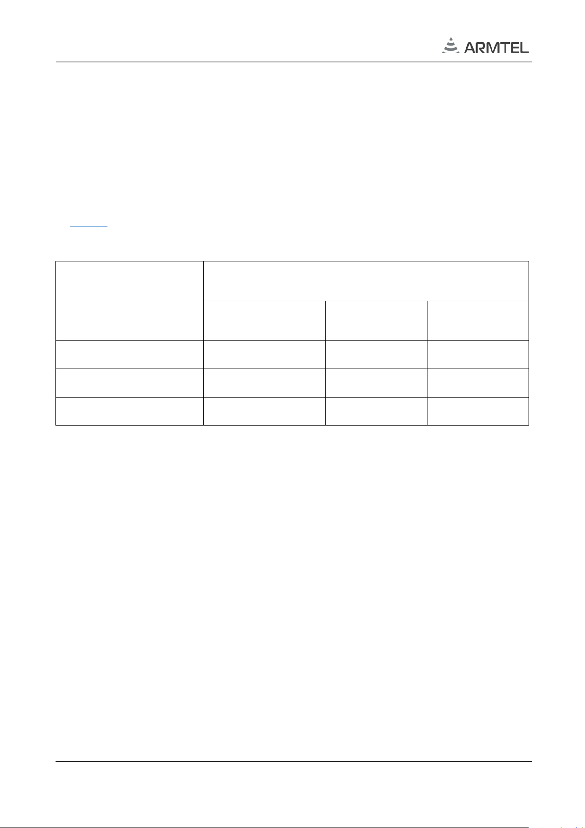
1.1.5.3 The printed board is housed inside the base with three-position DIP-switch
whereby the address of the Handset unit is set up via I2C interface in communication
mode. The address should be set up before TOP-HS-IP2 employment with regard
to Table 3. In this iteration, AD0 module address is set up by default.
Table 3 – Setting the address when connecting via I2C interface
Address number
TOP-HS-IP2
Positions of DIP-switches
1 2 3
AD0
OFF
OFF
OFF
AD1
OFF
ON
OFF
AD2
OFF
OFF
ON
1.1.5.4 TOP-HS-IP2 handset can be connected to any RJ-22 socket of the base via
the handset stretch cord provided.
Above the base stand through the slots in the housing are output connection cables
to the TOP-DIS-IR2 or TOP-PAD-IP2:
−the analog path of the TOP-HS-IP2 is connected to one of the RJ-22 4P4C
connectors;
−digital path I2C interface – to the socket RJ-25 6P6C (call station).

TOP-HS-IP2 HANDSET UNIT
User Manual
armtel.com page 11/32
info@armtel.com © Armtel
1.1.6 Labeling
On the bottom side of TOP-HS-IP2 casing is placed bilingual nameplate.
The nameplate contains the following information:
−name, trademark and reference information of the manufacturer;
−product name and description;
−permissible operating temperature range;
−degree of protection provided by enclosures (IP code);
−rated supply voltage value;
−electrical class III mark according GOST IEC 61140-2012;
−commercialization mark for products on the market of Customs Union member states;
−special waste disposal mark;
−product serial number;
−date of manufacture;
−MAC address;
−other information if necessary.
The serial number is unique for each product.

TOP-HS-IP2 HANDSET UNIT
User Manual
page 12/32 armtel.com
1.1.7 Package
The TOP-HS-IP2 with the assembly kit and documents, which come with the supply
package, is packed in consumer package (cardboard box) according to GOST 23088-80.
Before packing in consumer package (cardboard box), TOP-HS-IP2 with the assembly
kit and operational documentations are placed in plastic film covers that have the
corresponding marking. TOP-HS-IP2 is additionally exposed to temporary anticorrosion
protection with technical silica gel.
A label in Russian language and English language is glued onto the consumer
package, said label containing the following inscriptions and symbols:
−product name and description;
−name, trademark and reference information of the manufacturer;
−handling symbols according to GOST 14192-96 and CU TR 005/2011;
−commercialization mark for products on the market of Customs Union
member states;
−serial number and date of manufacture.
The package is made according to the drawings of the product manufacturer and
enables storage of TOP-HS-IP2, provided requirements set in Section 5 are met.
For shipment of TOP-HS-IP2 from the manufacturer, consumer package contents are
placed in the package place, which ensures protection from mechanical damage, direct
ingress of atmospheric precipitation, dust and solar radiation during transportation.
When exported, to remote areas or regions of the Far North, products are shipped as
part of a packaging place protected from external influences. The stacking height of the
package when sent as part of the container should be no more than 6 levels.
TOP-HS-IP2 HANDSET UNIT
User Manual
armtel.com page 13/32
info@armtel.com © Armtel
1.2 Description and operation of the product components
1.2.1 General information
The main components of TOP-HS-IP2 are as follows:
−TOP-HS-IP2 main board;
−handset microphone;
−handset speaker.
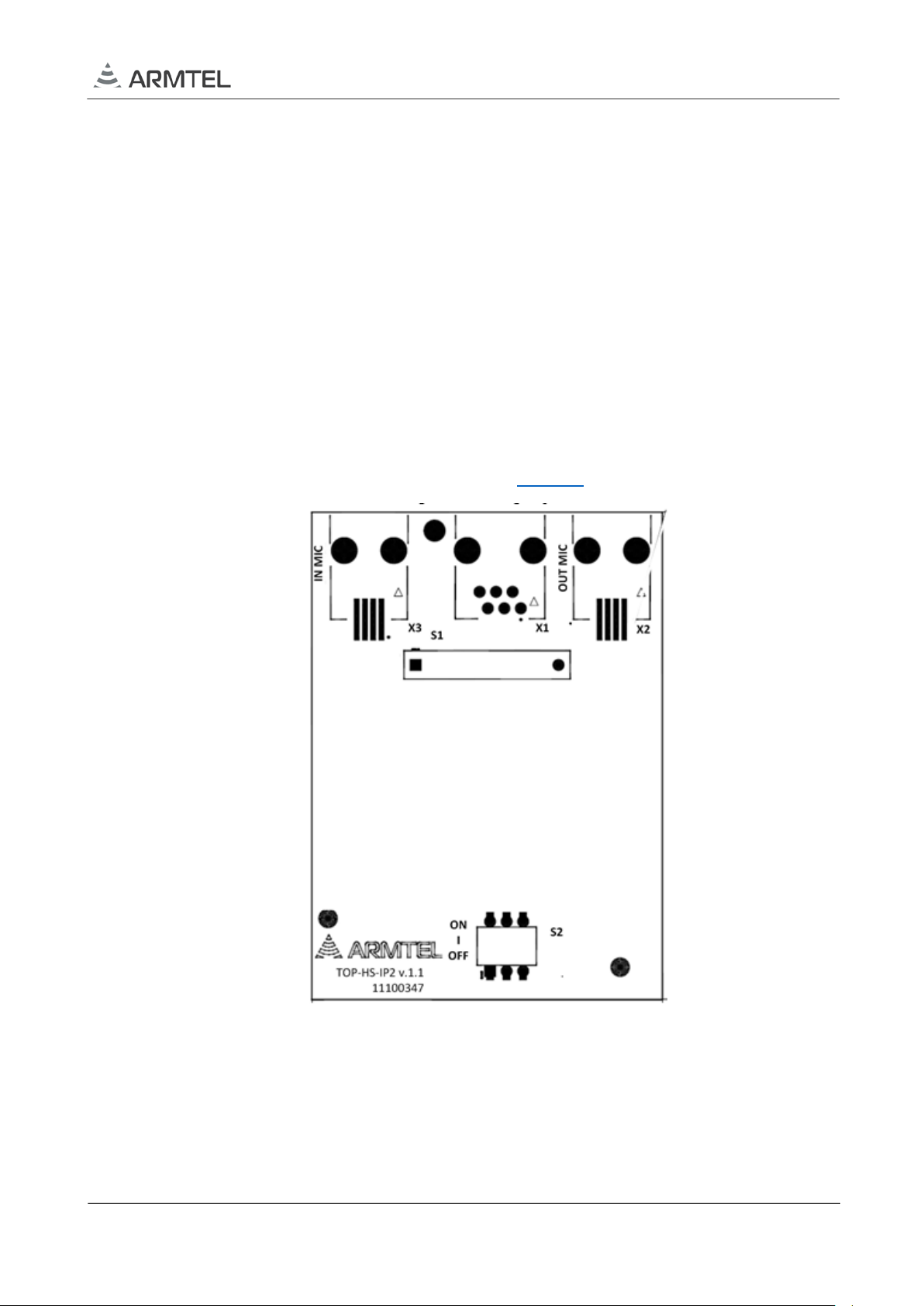
1.2.2 Main board
TOP-HS-IP2 main board is a printed board with installed electronic elements required
for functioning of the TOP-HS-IP2.
External appearance of main board is given on Figure 3.
Figure 3 – TOP-HS-IP2 main board
Figure 3 illustrates the following positions:
−X1: RJ-25 6P6C socket of the digital path to connect TOP-HS-IP2 Handset unit
via I2C interface;

TOP-HS-IP2 HANDSET UNIT
User Manual
page 14/32 armtel.com
−Х2and Х3: RJ-22 4P4C sockets of the analogue path of the Handset unit. Both
the handset cord and cable of the analogue path to connect TOP-DIS-IP2 or
TOP-PAD-IP2 will be connected to sockets X2 or X3 in random order;
−S1: the reed relay for receiving and clearing the call when picking up or
replacing the handset where applicable;
−S2: three-position DIP-switch to set up TOP-HS-IP2 address in I2C interface
path (see 1.1.5.4).
1.2.3 Handset microphone
Highly-sensitive microphone with the impedance of 2,2 kOhm and circle directivity is
installed in TOP-HS-IP2 handset. The microphone sensitivity is within the range
(-38 ± 3) dB and broad range of the perceived frequency from 100 Hz to 10 kHz.
The signal-to-noise ratio is more than 55 dB, the operation voltage is 2 V.
1.2.4 Handset speaker
The capsular dynamic converter of PDK-3 type complete with the electric resistance
module within the range from (300 ± 60) Ohm is applied in TOP-HS-IP2 handset, with the
frequency of 1000Hz and frequency response from 300 to 3400 Hz. The variation in
frequency response within the stated frequency range not exceeding 10 dB, the efficiency
of the converter, at the frequency of 1000Hz is equal to 4Pa.
TOP-HS-IP2 HANDSET UNIT
User Manual
armtel.com page 15/32
info@armtel.com © Armtel
2 INTENDED USE
The product is designed for continuous 24-hour a day operations. After
commissioning, the product does not require operator intervention, unless:
−maintenance;
−product configuration changes.
Maintenance personnel must be strictly guided by this document in compliance with
safety regulations.
The product along with the operational documentation is delivered to the customer
in packaged form.
2.1 Operating limits
2.1.1 The product shall be used under exposure factors and ambient parameters
which do not exceed permissible values given in 1.1.3.
2.1.2 The requirements for operating conditions and the choice of the place
of installation given in this document take into account the most typical
factors that affect the operation of TOP-HS-IP2.
Factors that cannot be predicted, estimated or verified, and which the manufacturer
was unable to factor in during development may exist or arise during operation at the
operating facility.
In the event of such factors, find another operating site where said factors do not
exist or do not affect operation of the product.
2.2 Preparation for use
Preparation of TOP-HS-IP2 for use shall be carried out by the manufacturer’s
representatives, or personnel trained to operate Armtel LLC products.
The main preparation of the product for use is carried out during installation and
connection:
−checking TOP-HS-IP2 package contents;
−visual inspection of the product for damage (cracks, dents, chips, etc.);
−install and connect TOP-HS-IP2 at the operating site (refer 2.4).

TOP-HS-IP2 HANDSET UNIT
User Manual
page 16/32 armtel.com
2.3 Safety precautions
TOP-HS-IP2 functions with the power supply of ultra-low 5V DC; no special safety
measures specified by local codes and regulations on electrical safety are required.
To avoid electric shock, do not:
−turning on the device with damaged power and interface cables or connectors.
Never dismantle the product connected to mains.
Installation and connection of the product only in a de-energized state.
Do not use the product in rooms with high humidity (more than 80 %) or conductive
dust.
In order to ensure fire safety, follow the following rules:
−before connecting the product to the power supply, make sure the power and
communication cables are properly insulated;
−protect power and communication cables from damage.

TOP-HS-IP2 HANDSET UNIT
User Manual
armtel.com page 17/32
info@armtel.com © Armtel
2.4 Installation, connection and dismantling
2.4.1 Basically, TOP-HS-IP2 should have a desktop-mounting. If TOP-HS-IP2 is
desktop-mounted, it is attached to TOP-DIS-IP2 and TOP-PAD-IP2 using aluminum
junction plates provided, which should be ordered complete with TOP-HS-IP2 in the
requested order. The dimensions of the plates, fixing mode and desktop mounting
configurations are given in Appendix B.
2.4.2 For wall-mounting and turntable-mounting of TOP-DIS-IP2 or TOP-PAD-IP2,
the TOP-HS-IP2 should be attached similarly to desktop mounting using junction plates
provided if desktop mounting.
2.4.3 The layout and recommendations for flush-mounting of TOP-HS-IP2 are given
in Appendix B.
2.4.4 Connect the handset to the base stand using the handset stretch cord provided,
connect both analogue and digital communication paths to the sockets located at the base
stand (see Figure B.2, Appendix B). The AUI cables for TOP-HS-IP2 are laid in the channels
of the base stand and enclosures of the desktop or panel-mounted call stations in
accordance with the directions given in the User manuals for TOP-DIS-IP2 and
TOP-PAD-IP2.
The address of TOP-HS-IP2 is not set up in I2C interface path for the given iteration.
2.4.5 TOP-HS-IP2 is dismantled in the following order:
−disconnect all connection cables;
−disconnect junction plates;
−in case turntable-mounting − remove the structure from the turntable and
detach junction plates to TOP-DIS-IP2 or TOP-PAD-IP2;
−in case wall-mounting – remote the structure from the bracket detach junction
plates to TOP-DIS-IP2 or TOP-PAD-IP2;
−in case flush-mounting – detach TOP-HS-IP2 from a desktop;
−pack in consumer package (cardboard box).

TOP-HS-IP2 HANDSET UNIT
User Manual
page 18/32 armtel.com
2.5 Operation
2.5.1 If TOP-HS-IP2 is used complete with TOP-DIS-IP2 or TOP-PAD-IP2, the full
duplex communication mode is established. With communication via TOP-HS-IP2,
the microphone, the speakers of the desktop or panel-mounted call stations will be turned
off. The flexible programming with availability to change the functionality in situ with
regard to the Customer requirements can be applicable for both TOP-DIS-IP2 and
TOP-PAD-IP2 complete with TOP-HS-IP2.
2.5.2 As the Handset unit is only applied when complete with TOP-DIS-IP2 or
TOP-PAD-IP2, the operating modes and functionality of TOP-HS-IP2 in detail are available
in the User manuals for TOP-DIS-IP2 and TOP-PAD-IP2.
2.6 Troubleshooting
Possible problems and solutions are given in Table 4.
Table 4 – Possible problems and solutions
Problem Possible cause Solution
Communication via
TOP-DIS-IP2 or
TOP-PAD-IP2 is
impossible
Handset cord or
communication cables with
TOP-DIS-IP2 or TOP-PAD-IP2
are switched off or damaged
Verify that the handset connection
cord and communication cables
with TOP-DIS-IP2 or TOP-PAD-IP2
are intact
Table of contents


