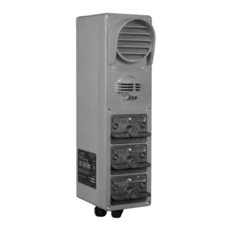
ARMTEL TOP-DIS-IP2 User manual

TOP-DIS-IP2
Desktop call station
RMLT.465311.009UM
User Manual
Document version 7
26.30.11.190
2020

armtel.com
© Armtel info@armtel.com

TOP-DIS-IP2 DESKTOP CALL STATION
User Manual
armtel.com page 1/64
info@armtel.com © Armtel
INTRODUCTION
This User Manual applies to «TOP-DIS-IP2 Desktop call station» RMLT.465311.009
manufactured by Armtel LLC, and is intended to familiarize the User with the device and the
procedure for its operation at the installation site.
Designed for organization of two-way communication as a component of IPN system
manufactured by Armtel LLC.
Short name of product – TOP-DIS-IP2.
Maintenance personnel for TOP-DIS-IP2 shall be appointed by the management at
the installation site.
The maintenance personnel shall be required to know the operating procedure of
TOP-DIS-IP2 to the extent provided for by the User manual.
The maintenance personnel shall be required to know the operating procedure of
TOP-DIS-IP2 to the extent provided for by the User manual.
Example of TOP-DIS-IP2 designation during ordering and in documentation:
« TOP-DIS-IP2 Desktop call station» RMLT.465311.009 or RMLT.465311.009-01 depending
of product version (see 1.1.1).
ATTENTION! In connection with systematic work to improve the design and
manufacturing technology, it is possible some discrepancy between the description and
the supplied product, which does not affect its operation or maintenance.

TOP-DIS-IP2 DESKTOP CALL STATION
User Manual
page 2/64 armtel.com
SAFETY PROVISIONS
During installation and operation observe the safety measures specified by local codes
and regulations on electrical safety.
During installation and operation, observe safety precautions laid out in “Occupational
safety rules when operating electrical installations” when working with electrical receivers
with voltage of up to 1000 V.
To avoid electric shock, do not:
−turning on the device with damaged power and interface cables or connectors.
ATTENTION! NEVER DISMANTLE THE PRODUCT CONNECTED TO MAINS.
Installation and connection of the product only in a de-energized state.
Do not use the product in rooms with high humidity (more than 80 %) or conductive
dust.
ВIn order to ensure fire safety, follow the following rules:
−before connecting the product to the power supply, make sure the power and
communication cables are properly insulated;
−protect power and communication cables from damage.
The safety provisions for specific operations described in this manual are marked with:

TOP-DIS-IP2 DESKTOP CALL STATION
User Manual
armtel.com page 3/64
info@armtel.com © Armtel
CONTENTS
INTRODUCTION.................................................................................................................................................................... 1
SAFETY PROVISIONS........................................................................................................................................................... 2
CONTENTS .............................................................................................................................................................................. 3
1 DESCRIPTION AND OPERATION................................................................................................................................. 5
1.1 Product description and operation .................................................................................................................. 5
1.1.1 Features ............................................................................................................................................................. 5
1.1.2 Main specifications........................................................................................................................................ 7
1.1.3 Operations conditions.................................................................................................................................. 9
1.1.4 Design...............................................................................................................................................................10
1.1.5 Labeling ...........................................................................................................................................................14
1.1.6 Package............................................................................................................................................................15
1.2 Description and operation of the product components ........................................................................16
1.2.1 General information....................................................................................................................................16
1.2.2 Main board.....................................................................................................................................................16
1.2.3 Functional keys .............................................................................................................................................18
1.2.4 Microphone....................................................................................................................................................19
1.2.5 Speaker ............................................................................................................................................................20
1.2.6 Wi-Fi module .................................................................................................................................................20
2 INTENDED USE ................................................................................................................................................................21
2.1 Operating limits .....................................................................................................................................................21
2.2 Preparation for use ...............................................................................................................................................22
2.3 Safety precautions.................................................................................................................................................22
2.4 Installation, connection and dismantling .....................................................................................................23
2.5 Operation .................................................................................................................................................................25
2.5.1 Turning on ......................................................................................................................................................25
2.5.2 Function keys assignment.........................................................................................................................26
2.5.3 Communication types and scenarios ...................................................................................................27
2.5.4 TOP-DIS-IP2 complete with TOP-HS-IP2 features ..........................................................................30
2.5.5 Troubleshooting...........................................................................................................................................31
3 MAINTENANCE................................................................................................................................................................32
3.1 General guidelines ................................................................................................................................................32
3.2 Safety precautions.................................................................................................................................................32
3.3 Maintenance procedure......................................................................................................................................32

TOP-DIS-IP2 DESKTOP CALL STATION
User Manual
page 4/64 armtel.com
3.4 Checking operability ............................................................................................................................................33
3.4.1 Initialization test ...........................................................................................................................................33
3.4.2 Checking acoustic path..............................................................................................................................33
3.4.3 Function keys test ........................................................................................................................................33
4 PEPAIR ..............................................................................................................................................................................34
5 STORAGE............................................................................................................................................................................35
6 TRANSPORTATION.........................................................................................................................................................36
7 DISPOSAL...........................................................................................................................................................................37
APPENDIX A (reference) Connection ..........................................................................................................................38
APPENDIX B (reference) Desktop mounting of the unit complete with TOP-EC-IP2 Expansion
unit and TOP-HS-IP2 Handset unit..............................................................................................................................42
APPENDIX C (reference) Wall-mounting .............................................................................................................47
APPENDIX D (reference) Turntable-mounting...................................................................................................52
APPENDIX E (reference) Recommendations on flush-mounting of TOP-DIS-IP2.................................53
APPENDIX F (reference) TOP-DIS-IP2 Indication types...................................................................................57
APPENDIX G (reference) A template for printing of function keys assignment......................................59
APPENDIX I (reference) Scope of supply ..............................................................................................................61

TOP-DIS-IP2 DESKTOP CALL STATION
User Manual
armtel.com page 5/64
info@armtel.com © Armtel
1 DESCRIPTION AND OPERATION
1.1 Product description and operation
1.1.1 Features
ТОР-DIS-IP2 is designed for use in distributed and centralized digital intercom and
Public Address /General Alarm communication systems (based on allotted SIP server
manufactured by LLC Armtel) at industrial and transport facilities.
TOP-DIS-IP2 is not intended for use in public networks and systems.
ТОР-DIS-IP2 is the subscriber equipment of digital intercom, and it provides loud-
speaking communication between subscriber equipment (manufactured by LLC Armtel),
duplex communication with subscribers of IP-telephony, Public Address, including automatic
one.
TOP-DIS-IP2 сan be applied in distributed and centralized digital intercom and Public
Address /General Alarm communication systems (based on allotted SIP server manufactured
by LLC Armtel) at metal, chemical, oil-processing, oil and gas, energy and transport industries
or at facilities of the same type. ТОР-DIS-IP2 is designed for installation in control, office
rooms and premises.
The external appearance of TOP-DIS-IP2 is illustrated at Figure 1.
Figure 1 – External appearance of TOP-DIS-IP2

TOP-DIS-IP2 DESKTOP CALL STATION
User Manual
page 6/64 armtel.com
ТОР-DIS-IP2 has two versions:
−RMLT.465311.009 − with Wi-Fi module (the basic version);
−RMLT.465311.009-01 – without Wi-Fi module.
TOP-DIS-IP2 Desktop call station performs the following functions within the digital
intercom system:
−simplex loudspeaker communication with subscribers via SIP protocols,
“Armtel-IP”, with a built-in speaker, a microphone on a flexible “gooseneck”
stand and function keys of direct call (FK);
−duplex loudspeaker communication of subscribers via SIP protocol;
−providing communication between the terminal devices over twisted pair using
two Ethernet ports with the function of “Ethernet bonding”;
−connection to the Ethernet network via wireless Wi-Fi (except for
RMLT.465311.009-01 version);
−recording and playback of voice messages on IPN terminal devices;
−processing of calls priorities of the protocols SIP, “Armtel-IP”, and “Call cancel“
function;
−organization of unilateral control mode in simplex intercom;
−duplex intercom manual control;
−indication of incoming and outgoing calls, line status (busy), missed call via
SIP protocols, “Armtel-IP” by means of function key illumination, as well as LED
indication on the front panel and on microphone;
−LED indication of Ethernet wired connection status;
−volume control of the built-in speaker using programmed keys with local
functions “Increase volume“ and “Reduce volume“;
−management of the АСМ-IP2 analogue subsystems module by means of
the function “Relay”;
−increasing of function keys total number up to 126 pcs. by connecting of up to
two Expansion units TOP-EC-IP2 RMLT.468366.009.
Configuration of TOP-DIS-IP2 shall be carried out using the personal computer of the
IPN network administrator on which IPN2 RU.RMLT.00041-01 IPN Config Tool software
configuration application is installed.

TOP-DIS-IP2 DESKTOP CALL STATION
User Manual
armtel.com page 7/64
info@armtel.com © Armtel
1.1.2 Main specifications
Main specifications of TOP-DIS-IP2 are given in Table 1.
Table 1 – Main specifications (beginning)
Parameters Value
Electrical parameters
Rated voltage PoE (IEEE 802.3at), V
48
Supply voltage range PoE (IEEE 802.3at)at turn on, V
42…60
Supply voltage range PoE (IEEE 802.3at)after turn on, V
36…60
External DC power supply, V
12
External DC power supply range, V
±10%
Reverse polarity protection
available
Maximum current consumption by PoE line, max*, А
0,36
Maximum current consumption at 12 V, max*, А
1,31
Power consumption, max, W
19,1
Output voltage supply of additional modules on the I2C line, V
(5,0 ± 0,25)
Rated output voltage supply of peripheral devices on USB
line**, V
5,0
Rated voltage PoE (IEEE 802.3at), V
48
Acoustic path
Speech bandwidth at 0.3 dB level, Hz
from 300 to 6800
Built-in speaker, pcs.
1
Gooseneck microphone, pcs.
1

TOP-DIS-IP2 DESKTOP CALL STATION
User Manual
page 8/64 armtel.com
Table 1 - Main specifications (continuation)
Parameters Value
Data lines
Ethernet communication interface ***
10BASE-T (IEEE802.3i)
100BASE-TХ(IEEE802.3u)
Channel bonding
(IEEE802.3ad)
Communication protocols via Ethernet
SIP, «Armtel-IP»
Communication buses with auxiliary modules
I2C (Armtel),
USB 2.0
Wireless communication interface
Wi-Fi 2.4, 5.0
Communication protocols via Wi-Fi
IEEE 802.11a/b/g/n/ac
External Connection Interfaces
Ethernet connection, pcs.
2 ( RJ45 / 8P8C)
Auxiliary modules I2C connection, pcs.
2 ( RJ25 / 6P6C)
Handset connection, pcs.
2 ( RJ22 / 4P4C)
Auxiliary modules USB 2.0 connection, pcs.
1 ( USB type A)
Additional power connection, pcs.
1 (DC2,1x5,5 socket)
Controls and information display
Functional keys, pcs.
42
Display 4,3”, pcs.
1
LED indication
Microphone
Functional keys
Housing
Ethernet sockets
Design parameters
Weight, kg
(1,56 ± 0,08)

TOP-DIS-IP2 DESKTOP CALL STATION
User Manual
armtel.com page 9/64
info@armtel.com © Armtel
Table 1 - Main specifications (end)
Parameters Value
Other
Electrical safety class under GOST IEC 61140-2012
III
* Excluding consumption currents TOP-EC-IP2 and TOP-HS-IP2;
** USB line output voltage limit accordance with USB 2.0 specification;
*** Two Ethernet ports, one of which is a reserve, including the power of PoE.
1.1.3 Operations conditions
Environmental requirements for TOP-DIS-IP2 in operating mode:
−ambient temperature range from minus 20 to plus 40 °C;
−relative humidity up to 80 % at 25 °C, at lower temperatures, without
condensing;
−atmospheric pressure within the range from 84 to 106,7kPa.
Note - The limiting low ambient temperature, after the effect of which, the normal
functioning of the product is guaranteed is minus 20 °C.
Ingress protection of TOP-DIS-IP2 complies with IP42.
TOP-DIS-IP2 complies with the requirements electromagnetic interference according
to IEC 61000-6-2:2005, with not lower B quality criterion. The electromagnetic interference
from TOP-DIS-IP2 does not exceed the codes specified in IEC 61000-6-4:2006.

TOP-DIS-IP2 DESKTOP CALL STATION
User Manual
page 10/64 armtel.com
1.1.4 Design
1.1.4.1 The external appearance and overall dimensions of TOP-DIS-IP2 in desktop
version and with G14-2 microphone are illustrated at Figure 2.
1
2
3
5
46
7
8
910 11 12 13 14 15
19 18
17
20 20
16
16
267
1 – LED indication on the microphone; 2 –microphone; 3 – stand; 4 – built-in speaker;
5 –LED indication on the front panel; 6 – display; 7 – cover assembly with logotype of
the manufacture; 8 – keys; 9 – enclosure base; 10 – plate with sockets for external connections;
11 –RJ-22 4P4C socket for connection of Handset unit analog path; 12 – RJ-25 6P6C sockets for
connection of Handset unit (right socket) and/or Expansion unit digital path (right and left sockets);
13 – USB 2.0 port; 14 – RJ-45 8P8C sockets for Ethernet interface connection; 15 –socket for external
12V power supply connection; 16 – cable slots; 17 – radiator; 18 – «Reset» Button; 19 – Name plate
and MAC-address identification plate; 20 – legs.
Note - Plugs for connection sockets and stand legs are not shown.
Figure 2 – External appearance and overall dimensions for TOP-DIS-IP2

TOP-DIS-IP2 DESKTOP CALL STATION
User Manual
armtel.com page 11/64
info@armtel.com © Armtel
TOP-DIS-IP2 can be used in desktop version, in wall-mounted version, can also be
mounted on a turntable or flushed into the desktop, made of wood, metal or plastic. For
more information, see the Section “Installation, connection and dismantling” of this Manual.
1.1.4.2 ТОР-DIS-IP2 is designed in a flat plastic enclosure, adjustable stand provides
the inclination angle for better visibility of keys and display. To impart stability, the stand
and turntable are equipped with rubber legs at the bottom.
To impart stability, the stand is equipped with rubber legs at the bottom. To adjust the
stand in desktop version, see Figure 3:
a)
b)
c)
Figure 3 – Adjustment of the stand for Desktop call station
To adjust the stand:
a) turn the unit upside down disconnecting it from the power supply and
interfaces, pull out four plugs from the grooves to install the stand and
simultaneously press the two latches at the base of the stand;
b) insert the stand stoppers in the far-end grooves in the bottom of the enclosure;
c) push the stand into the near-end grooves.
Remove the stand in the reverse order.
1.1.4.3 To provide wireless communication in the basic version of RMLT.465311.009
Desktop call station (with Wi-Fi module), the built-in dual band Wi-Fi antenna Molex
1461530150 is used, which is fixed in the cover of the panel above the main board.
The antenna has a gain value of 2.8 dBi at 2.4 GHz and 4.2 dBi at 5 GHz, that allows the
wireless access point to be located at a distance of up to 100 meters from TOP-DIS-IP2 or
more - depending on the characteristics of the antenna on the access point. The external
appearance of Wi-Fi antenna is illustrated at Figure 4.

TOP-DIS-IP2 DESKTOP CALL STATION
User Manual
page 12/64 armtel.com
Figure 4 – External appearance of Wi-Fi antenna
1.1.4.4 A plate with the designation of sockets for external connections located on the
base of the enclosure is shown in Figure 5.
Figure 5 – The plate with the designation of sockets for external connections
1.1.4.5 To ensure a reliable connection of TOP-DIS-IP2 cables, they can be placed in
special grooves in the base of the enclosure (4 pcs.) and in the stand (2 pcs.) in accordance
with Figure 6. When TOP-DIS-IP2 is supplied to the customer, the grooves in the base of the
enclosure are closed with special plugs (not shown in Figure 6), which must be removed from
the grooves before the cables are laid.
1 – grooves in the stand; 2 – grooves in the base of the enclosure.
Figure 6 – Grooves for laying of communication cables
1
2

TOP-DIS-IP2 DESKTOP CALL STATION
User Manual
armtel.com page 13/64
info@armtel.com © Armtel
1.1.4.6 When TOP-DIS-IP2 is equipped with TOP-EC-IP2 Expansion units and/or with
TOP-HS-IP2 Handset unit, they are connected to the Desktop call station by cables of
additional modules provided in accordance with Figure 2. The Expansion unit is connected
to RJ-25 socket via I2C interface, the analogue path of the Handset unit is connected to
RJ-22 socket, the digital path - to RJ-25 socket.
1.1.4.7 USB 2.0 socket (see Figure 2) is provided for connecting ADSL external adapter
in subsequent modifications of the Desktop call station for communication of subscriber
devices with ADSL interface included in IPN system.
1.1.4.8 Power supply of TOP-DIS-IP2 is carried out via PoE line in accordance with
IEEE802.3at standard, and in the form of passive power over twisted pair (passive PoE),
without data transmission as well, when one port is transmitted data, the second – power. If
PoE injector is not available, an external 12 VDC power adapter is provided.
1.1.4.9 When using the “Ethernet bonding” function, in addition to the main cable
Ethernet (Patch Cord) connected to RJ-45 socket on the base of TOP-DIS-IP2 enclosure, an
additional Patch Cord should be connected to another RJ-45 socket in accordance with
Figure 2. Both cables are connected to the Ethernet switch. In this case, when configuring
TOP-DIS-IP2 in the IPN Config Tool, in the “Parameter” window in the “Working interfaces”
tab it is necessary to set the checkboxes for the ports “eth0” and “eth1” should be ticked. In
this way, the Ethernet channels are duplicated and automatically switched to the redundant
channel in the event of malfunction or failure in the primary channel of the Ethernet interface.
1.1.4.10 At the top of the front panel (above the display) there is a LED that indicates
the type of incoming or outgoing communication by solid light or blinking (see
Appendix F).

TOP-DIS-IP2 DESKTOP CALL STATION
User Manual
page 14/64 armtel.com
1.1.5 Labeling
On the bottom side of TOP-DIS-IP2 casing is placed bilingual nameplate.
The nameplate contains the following information:
−name, trademark and reference information of the manufacturer;
−product name and description;
−permissible operating temperature range;
−degree of protection provided by enclosures (IP code);
−rated supply voltage value;
−electrical class III mark according GOST IEC 61140-2012;
−commercialization mark for products on the market of Customs Union member
states;
−special waste disposal mark;
−product serial number;
−date of manufacture;
−other information if necessary.
The additional plate shows MAC address.
The serial number and MAC address are unique for each product.

TOP-DIS-IP2 DESKTOP CALL STATION
User Manual
armtel.com page 15/64
info@armtel.com © Armtel
1.1.6 Package
The TOP-DIS-IP2 with the assembly kit and documents, which come with the supply
package, is packed in consumer package (cardboard box).
Before packing in consumer package (cardboard box), TOP-DIS-IP2 with the assembly
kit and operational documentations are placed in plastic film covers that have the
corresponding marking. TOP-DIS-IP2 is additionally exposed to temporary anticorrosion
protection with technical silica gel.
A label in Russian language and English language is glued onto the consumer package,
said label containing the following inscriptions and symbols:
−product name and description;
−name, trademark and reference information of the manufacturer;
−handling symbols according to GOST 14192-96 and CU TR 005/2011;
−commercialization mark for products on the market of Customs Union member
states;
−serial number and date of manufacture.
The package is made according to the drawings of the product manufacturer and
enables storage of the TOP-DIS-IP2, provided requirements set in Section 5 are met.
For shipment of the TOP-DIS-IP2 from the manufacturer, consumer package contents
are placed in the package place, which ensures protection from mechanical damage, direct
ingress of atmospheric precipitation, dust and solar radiation during transportation.

TOP-DIS-IP2 DESKTOP CALL STATION
User Manual
page 16/64 armtel.com
1.2 Description and operation of the product components
1.2.1 General information
The main components of TOP-DIS-IP2 are as follows:
−TOP-DIS-IP2 main board;
−functional keys;
−microphone;
−speaker;
−Wi-Fi module.
1.2.2 Main board
TOP-DIS-IP2 main board is a printed board with installed electronic elements required
for functioning of the TOP-DIS-IP2.
External appearance of main board is given on Figure 7.
a) key side view
Figure 7 – TOP-DIS-IP2 main board (beginning)

TOP-DIS-IP2 DESKTOP CALL STATION
User Manual
armtel.com page 17/64
info@armtel.com © Armtel
b) CPU module side view
Figure 7 – TOP-DIS-IP2 main board (end)
Figure 7b includes:
−U1: central processing unit CPU;
−Х2: socket for external 12 V power supply connection;
−Х1, Х3: sockets for Ethernet connection with РоЕ function, indicators on the
sockets are constantly lit in green when physical connection with Ethernet is
established, blinking - when the network interface is active (either sending or
receiving), and constantly lit in orange –the unit supplies from PoE source;
−Х16: USB2.0 socket;
−Х7:RJ-25 socket for connection of Expansion unit via I2C interface;
−Х8: RJ-25 socket for digital path connection of Handset unit and/or Expansion
unit via I2C interface;
−Х27: not used in now product version;
−Х28: sockets for analogue path connection of Handset unit;

TOP-DIS-IP2 DESKTOP CALL STATION
User Manual
page 18/64 armtel.com
−Х30: socket for built-in speaker connection;
−Х31: socket for microphone connection.
The core of the main board is the CPU module with MCIMX6U5EVM10AC processor
with ARM Cortex A9 core of maximum clock frequency of 1 GHz and 512 KB of
programmable memory. When the power supply and interface are connected, the main
board ensures the functioning of TOP-DIS-IP2 according to the algorithm assigned in the
IPN Config Tool. The TOP-DIS-IP2 main board has the sockets that are connected to the
enclosure base for connecting cables to the Ethernet network, Handset unit and Expansion
units, the USB socket, and the external power supply socket.
On the back side of the board there are LEDs for the keypad illumination (see Figure
7a), as well as the contact pads for each key, the closure of which, when the keys are pressed,
results in the specific function assigned to the TOP-DIS-IP2 key.
1.2.3 Functional keys
The keys with LED illumination are arranged by seven pieces in a row, the number of
rows is six. The keys are equipped with a silicone membrane to ensure the declared safety
degree of TOP-DIS-IP2. Any key can be assigned from the Config Tool of IPN configurator
to connect to subscribers or local functions (for example, “Cancel”, when you press a key
with this function, the connection is disconnected).
Each key consists of a transparent cap, a pusher and a base. When you press the key,
the conductive base closes the pads on the main board. There are two ways of keystrokes
processing programmatically. In one case, pressing is treated as closing the contact,
releasing the key - as an opening the contact. In other case, the closure of the circuit is
remembered after the key is released, while the second pressing of the key is treated as an
opening. Methods for keystrokes processing are specified in the IPN Config Tool as
the activation or deactivation of the “Locked-in” function.
The transparent cap of each key is illuminated by the LEDs located below the keys on
the main board. Types of LED indication of the keys during the realization of various
programmed functions are given in Appendix F.
The keys have higher mechanical strength and wear-resistance.
Keys have no any signs, and A4 paper sheets can be used to designate the keys
functions. Function labels are printed on the printer and placed under transparent caps of
FK. A template for printing is given in Appendix G.
here is a slot on the key side for the convenience of function signs placing (see
Figure 8). It is necessary to open the cap of the key, then insert a paper element with the
printed designation of the function prepared in accordance with the template (Appendix G)
inside the cap and latch the cap back.
This manual suits for next models
2
Table of contents
Other ARMTEL Software manuals
Popular Software manuals by other brands

Samsung
Samsung HXSU025BA - S1 Mini - Hard Drive user manual
Alcatel
Alcatel CS1000 R7.5 Information
Bay Networks
Bay Networks Baystream 7 Notice
Brother
Brother PED-BASIC instruction manual
Red Hat
Red Hat DEVICE-MAPPER MULTIPATH 4.6 Configuration and administration guide
Allied Telesis
Allied Telesis AT-S79 user guide
