Arnold Company 490-241-0032 User manual

ASSEMBLYINSTRUCTIONS
DELUXEUNIVERSALSNOW CAB
490-241-0032
IMPORTANT:
See backfor parts
identification page
beforeyou begin
assembly.
"°. ! o . I
G_.,tthe free mobile _pp at
httpJige:tag.mobi

ToolsRequired:
3/B';9/16" and112"boxwrenches(netincluded);
Allen wrench(included). 3/8" I/2" 9/_6"
CAUTION:WEARINGSAFETYGLASSESISRECOMMENDEDDURINGASSEMBLY,
Assistance from another person is recommended for certain steps,
Refer to parts identification sheet to ensure you have all necessary parts,
Assembly Instructions:
t. Lay setsof barsA & B onafiat surface.SlideA& B
all theway together.Wait untiltheentire frameis
assembledbeforecompletelytighteningset screw (S)
with theenclosedAllen wrench.Insert set screw (S)into
the endofbar B, securingfinger-tight. Repeatwith
other set ofbars A& B.
Attachbar Eto theBendofthe A/B assemblies.
Insert set screw(S),securingin fingePtight at the end
ofbars Bwhere arrows point.Makesurenuts on
barE faceassembliesAiB.
Insert polesF,narrow end up,into the unionof barsE,
A& B.(Caution;Thisisa looselit; donotforce.) ii!! ii ! ill!iliii !!!i!i!ilil

Insert onepole Gintothe AendofbothAIB assemblies.
Make surethe nutof pole(3is upandfacingthefront.
insert set screw (S)into topof barsA, securingin
finger-tight.
!iiiiiii
Placecurvedbar Confiat surface,nutsfacing up.
Insert the labeledend ofcurvedbar Dinto G(making
sure arrows meet).Repeatwith the otherbarDon the
oppositeend of bar C.Insert set screw (S)into endsof
barsC,securinginfinger-tight.
6, Ptaceassembly'DiC/DontoendsofpolesG.Insert
set screw (S)attopof po_esG,securingin finger-tight.
NOTE:Make sureset screws arefacing towards
the front,
7, Makesurecabframe isin theshapeofa box,with
rightangles, Thentighten alltheset screw (S),using
the enclosedAllenwrench,
8. Grasptwoflexible Hrods, Insertthesteelcollarend
of theflexible1trodinto the otherflexibleH rod.
Repeatwith theothertwo flexibleHrods, insert two
sets offlexibleHrods intothetwo Fpoles.
NOTE:FlexibleHrods will feel loose
wheninserted,Thisiscorrect,De
net attempt to force flexibleHrods
further intopolesF.

9, Insert flexible rod Iinto one sideofthe setof flexible
rodsH.Carefullybendtheassembly to insertthefree
endofflexible rod I intothe otherset of flexiblerodsH.
CAUTION:Rodsareunder stress at
thistime, Safety glassesshouldbe
wornduringthisstep, untilthe
next step iscompleted,
10. Removefabric from carton and unfold,Standat the
rear endof the cab frame,facingthefront. Withfabric
in hand, and making surethe reflectivefabric is onthe
outsideofthe cab frame,slide the insidefabric pocket
overflexible rod assemblyH/Hi!/H/H.
NOTE:Besurerod assembly H!H/I/HIll is fully inserted
into thetop of the inside fabric pocket.
Fabric pocket
11.Pullthe cab materialdownandbacktowards the arch
assembly,D/C/D.Fastenhook-and-loopstrapson both
sides ofthe D/C/Dassembly.Slideelastic loopsover
the rear cornerof barA onboth sides. Fastenhook-
and-loopstraps aroundoil bars at variouslocations.
(Foryour convenienceyou maywantto wait until the
cab is mountedonyoursnow 1hrowertofinish
fastening thesestraps.)

12.Yourc]arr_scanbe pro-assembled. Lower Han_[leBars
(HorizontalTubeMount) UpperHandleBars
(Ve_ioaiTubeMount}
Thepreferredorientationofthe clampassemblyisto have
the saddtesperpendicularto oneanother,Threadthe small
bolt Pinto thecenterofK& Lassemblies,finger-tight,
Slidesmallertube, L,intolargertube, K.
13, NOTE:Noticehowcrossbarwill sit [nclamp
assembliesoncecramps are mountedonunit.
14.Todeterminethegenerallocation anddirectionfor
the crossbar(J),haveanassistanthold thecabat the
desiredlocationovertheunit.
NOTE:Dependingonyourunit,thecrossbarmay be
positionedfacingforward or backward,andabove
orbelowanylinkage.
15, Holdingcrossbar(J)indesiredlocation,_electarea
to mountclampassembly.
NOTE:BruteandJohnDeereunitsmay requireyouto
mount to the horizontalhandlebarsonthe unit.
NOTE:Preferredpositionison the verticalportion
of theunit'supperhandlebars.
Uppervertical
handtebars LowerhQdzontal
handlebar

16.Takepre-assembledK, L&M clampassemblies.Mount
assembliesK& Lin the determinedlocationonunit. Use
platesMand largebolts N,lock washer Tand nuts Rto
secureK,L& Massembliesto unit. Nowtighten small
bolt P so bothctampassembliesextendequaldistance
from frame.
17. Placecrossbar(J)againstassemblyK& LCenter
crossbar(J) againstunit, Usetwo remainingMplates,
largeboltsN, rockwasherTand nutsRto secure
crossbar.
NOTE:Make sureopen end of crossbar is facing up,
Besureendwith tabis facingdown,

18. Fullyinsert theendsof thefront ofthe cabassembly
into theendsof thecrossbar (J).Insert set screws (S)
into endsof crossbar(J).With assistantholdingcab
assemblyhorizontalto theground,tightenall boltsand
setscrews.
19. Finishassemblybyfastening all hook-and-loopstraps
insidethe cab if notcompletedatearliertime.
CAUTION:No cabfabric shouldbeallowedto touchengine
orexhaust,
20, Usinghook-and-loopstraps,secureconvenientpouch
onthe insideof yoursnowthrower cab,
2_.Thecab is designedto accommodatesnowthrowers
equippedwith alight,Zippersonthefront ofthe cab
can beopenedandtheflaps pulledbackandsecured
with hook-and-loopstrapsto allowthe lightto shine
through.Atthis time, adjustmentsmay benecessary
for free movementof operationcontrols.

INSTRUCCIONESDE MONTAJE
CABINAUNIVERSALDELUJOPARABARREDORASDENIEVE
490-241-0032
IMPORTANTE:
Vea a! dorso la p_gina de
identificaci6n de piezas
antes de comenzar el
montaje.

Herramientasnecesarias: _.,f,-
Llavesestriadas de318"(9.5ram),9/t5" (14.3ram)
y_" (12.7ram)(noinciuidas);LlaveAllen(incluida), v 3t8" (9.5ram)
ATENCION:SERECOMIENDAUSARGAFASDESEGURIDADDURANTEELMONTAJE,Se
Recomienda contar con ]a ayuda de otra persona para a]gunospasos,
Consultela hoja deidentificaci6nde piezaspara asegurarse detener todastaspiezas necesarias.
Instrucciones de mentaje:
t. Celoquelosconjuntosde barrasAyBsobreuna
superficie plana.DesiiceAy13hastajuntarlas. Antes
deapretar per completeel torni]lode fijaci6n(S)conIa
IlaveAlien incluida,espereaquese monteel bastidor
completo.Inserteel torni!le defijacidn (S)enel extreme
dela barra B;apri_tetoconIatuerzade [amane.Repita
el procedimientocon el otto conjuntodebarrasAy B.
Noti;e orientation of ba_:B
Fiie[abarra E al extreme Bde loscenjuntosA1B.Inserte
e[ternilio defijacidn(S)y apridtelocon Iafuerza de la
maneen el extremede lasbarras8, dendeapuntan
lasflechas.Aseg_resedeque[astuercasde]a barraE
quedenenfrentadasalos conjuntosA/B.
3, [nsertelos pitaresF,con el extremeangostohacia
arriba,en la uni6r_detas barrasE,A y B,
{Atenci_n:este es unajusteconhelgura;no 1ofuerce)

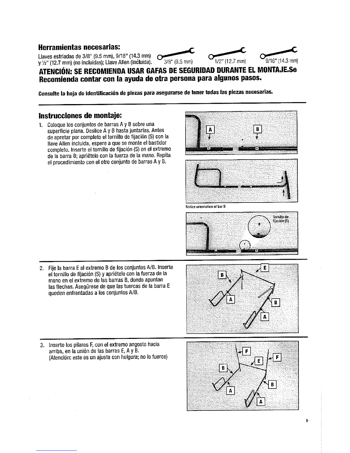
InserteunpitarGenelextremeAdeambosconiuntos
AIB.Aseg_resedequelatuercadelpilafGestdarribay
orieniadahaciaelfrenie.Inserteeltornilledefiiacion(S)
enelextremesuperiordelasbarrasA;aprieteloconIa
fuerzadelamane.
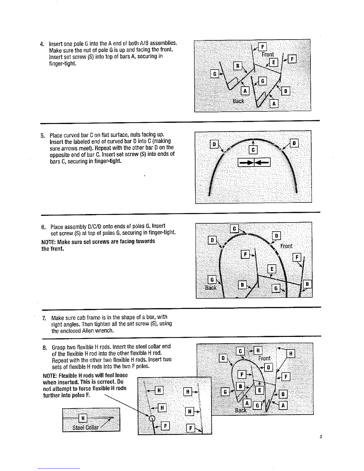
ColoqueIabarracurvadaCsobreunasuperficie
plana,conlastuercasorientadashaciaarriba,Inserte
elextremeetiquetadodela barra curvadaDen C
(aseg_resedequelas flechasse encuentren).Repitael
procedimientocon la etra barra Denel extremeopuesto
de la barra C.lnserteel tornillo de fijaci6n(S)enlos
extremesde lasbarrasC;aprietelocenfafuerza dela
mane,
6, Celoqueetcon_nto DfCIDenlosextremesdelos pilares
6. Inserte el tornilio defijaci6n(S)entapartes_perior
delos pilaresG;apri6telocon la fuerzadela mane.
NOTA:Asegbrese de quelos tornillosdefijaci(in queden
orientadoshaolee!frente,
7. AsegL_resedequeel bastidordetacabinatengala forma
de unacaja,con _,ngulosrectos.Luegoaprietetodeslos
ternillosdefijacion(S)per mediodelaIlaveAllenincluida,
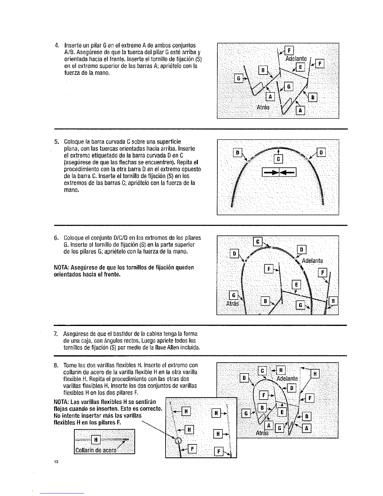
8. Tome]as dosvarillasflexibles H.Inserte el extremecon ,:: :,::_,::,::_ ::,:,---_:_: : _;_::,:::_:
celladn de acero dela variliaflexible Henla otravarilla ; i_,i::i :!
fle×ib}eH, Repitael procedimientoconlas otrasdos I : ': _gL-_L_II_A de]ante
variuasfiexibles H.lnsertelos dosconjuntosdevarillas :_': :::i:;_'_ :i ,/
fexbesHen osdesp aresF :: :i
flojas cuandoseinserten. Estoeseorrecto, ?::i:_ ::: :=: :r::7 ; k"_:'_l B_-, Ti:::;;
No intenteinsertarm_s lasvadllas i:_ !: :_! ::
flexibles Hen los pilaresF, "_ _;;:::_i::;:::_.... : : : : !_:
t0

9. Inserte la varillaflexible Ien unlade deIconjuntode
varillasf{exiblesH.Flexioneconcoidadoel conjunto
para insertarel extremelibre de lavarilla flexibleIen el
otto conjuntode varillasflexibfesH.
ATENCI6N:Eneste memento tas
varillasestansemetidasaesfuerzo.
Oebenusarsegalasdeseguridad
duranteeste paso,hastaquela
cubiertaest_colocadasobre
estasvarillas.
10,Retireia tela delacajayexti_nda{a.Col6queseenel
extreme posteriordelbastidorde lacabina,mirandohacia
e]frente. (;onla tela en Iamane,asegt_resedequela tela
refleetivaest_en etladeexteriordel bastidorde]acabina
ydeslicela cavidadde la te]ainterior sebreetconjuntode
varillasflexibies H!H/I/HIH.
NOTE:Cuidequeelconjuntode varillasHIH/I/HfHest8
completamenteinsertadoenla partesuperiordelacav{dad
delatelainterior,
Cavidad
1I. Tiredot materialdoIacabina haciaabajoy arras,haoia
el conjunto dearcoDiC/O.Sujetelastiras develcro
de ambosladesdel conjunto D/C/D.Desiicelos lazes
el_.sticossobre elanguloposterior deIabarraAen
amboslades,Sujetelastiras develcroalrededorde
todaslasbarras envaries lugares,
(Paramayorcemodidad,puedeesperarbastaquela
cabinaest6 montadaensu barredoradenievepara
sujetar eetastiras)

12, Sus mordazas pueden montarse previamente.
Laorientaci6npreferida del conjunto de mordazaes con las
partesc6ncavas perpendicularesentresi. Enresqueel perne
pequeSo9 enel centre delosconiuntosdeK y L,con ]a
fuerza de la man& Enresquelospernos flojamente.
Man_bdosinfedoros
(monta}edetubehorizontal ManubdosSuporiores
(montajedBtubevedical)
t
13, NOT/},:Observecomee!travesa_ose apoyaraenlos
conjuntosde mordazauna vezquelasmordazasest_n
mentadasen taunidad
14.Paradeterminar la direcci6n y ubicaci6ngeneralde!
travesaffo(J),haga queun asistentesostengala cabina
enla ubicaci_ndeseadasobre la unidad.
NOTA:Seg_n cu_lsea su unidad,el travesa_mpuede
colacarseorientado hacia adelante o haciaarras,
y perencima odebajode cuaiquier
elementoarticulado.
15.Sostengael travesafie enla ubicaci6nelegida y
seleccieneetareapara el montajedel conjunto
de mordaza.
NOTA:Las unidades Brutey JohnDeererequerir,_n
el montaje demanubrioshorizontaies.
NOTA:Laposicionpreferidaes en la percion vertical
de los manubriossuperiores de launidad,
ManubriDs
vedicWessuperiores Manubdo
horizoatalinfader

16,Monte losconjuntos Ky L enla ubicaci6ndeterminada
data unidad.(La mordazaKesmayorqueia mordazaL).
Utilice lasptacasM,lospemos grandesNy lastuercas
Rpara sujetarlos oonjuntosK, LyMa la unidad.
Ahora aprieteel pernopequeSoPdemodo queambos
conjuntosdemordazase extiendanadistanciasiguales
de_bastidoro
17. Coloqueel travesafiocontra la plata K, Cenlreel
travesaSocontra la unidad.Utifice lasdosplacasM
restantes,lospemos grandesNy lastuercas Rpara
sujetarel travesa_o.
NOTA:Aseg_resedequeel extremeabiertodeltravesafio
est_or_entadohaciaarriba, Cuide deque el extremocon
leng_ietaesteorientadohaciaabajo.
_3

18. Inserte per complete losextremesdeI frentedet
conjunto decabinaenlosextremesdel travesaSo(J).
Inserte lostorniflos de fijaci6n (S)ell losextremesdeI
travesa_o(J) y apfi6teloscon la fuerzade Iamane.
Conun asistenteque sostengael cenjuntedecabina
enposici6nhorizontal,apriete todoslospernosy los
ternillos defijaci6n.
19. Parefinalizar el montaje,sujetetodas Iastires de velcre
del interior dela cabina.
ATENCI()N:Nodebepermitirsequeningunaporciondela
telade la cabinatoqueel motor oel escape.
20. Sujete]aboise muttiusoenel interior dela cabinadesu
barredorade nievemediantetires develcro,
2t, Lacabinaest,,diseSadaparaadaptarsealas barredoras
denieveequipadasconunaluz.Lascremallerasqua
est_n enel frentede la cabinapuedenabrirsey los
faldonespuedenjalarse haeiaatr,_sy sujetarsecon]as
tires develcro,pare permitirquaialuzpaseatrav6s. En
este puntopuedequesenecesitenajustespareasegurar
el movimientolibra deloscontrolasdeoperaciSn,
14

INSTRUCTIONSDJASSEMBLAGE
CABINEDENEIGEUNIVERSELLELUXE
490-241-0032
IMPORTANT:
Voir au dos pour la
page d'identification
des pi_ces avant
de commencer
Vassemblage,

Outilsrequises:
3t8',' 9t15" et 112"c[espolygonales(noninclus);
Ct_Hexagonale(inclus).
AVIS: PORTERDESLUNETTESDES_:CURITEESTRECOMMANDEAUCOURSDEMONTAGE,
Assistanced'uneautre personneest recommandeepourcertaines_tapes.
Voirfiche d'indentificationdes pi_cespourvousassurerd'avoirtoutesles pi_cesn_eessaires
Instructions de montage:
1, PlacerensemblesdebarresAet Bsur unesurface planet
GlisserAet 8 tout le cheminensemble.Attendre que
lesquelette entier soit assembI_avantcomp_6tement
serr_ tesvis de pression(S)avecla cl_hexagonale
incius.Insdrerdes visdepression(S)_lafin dubar
B,securisationetancheaudoigt, Rdp_tezavecautre
ensemble debarresdeAet B.
Avi_ de _'_denla_i_n du bar 8
ii
Joindrebar Ea lafin de Bde I'ensemhleAIB, InsUrerv[s
depression (S),s_curisation dedoigt _tanche_la fin
des barresB ohIesfl_ches peintent.Faitcertain que
tes_crous surbarre Efent faceles ensemblesAIB,
i_iiii'iiiiiii!i!i_i,liiii_iiii_i_iiiiiil¸__ii_ilii_!,_iF:¸?i!ii_i:i:_:_i!i¸i_¸¸___:_":i_¸ii!_!!,i_:i!i:_i_ii!i!¸i!:illi
lns_rez Ies p61esF,extr_mit__troite, dartsf'uniende
bars E,A& B.
(Mise engarde'.IIs'agit d'unajustement I_che; ne
pas force.) _iii!i!i:i_ii_i_¸il!_ii:ili!!ii!i_ii!_!i_!:ii!_i_ii_!!!_: i_i_:_:i_:!!_i_!i_i_!_i_!iiiiiiii_ilili!i
!!iii!!!!!iiii!iiii!

4, tnsererun pGleG danstafin A deoieuxensemblesAtB.
Assurez-vousqueI'_sroudupGleGest enhautetface
_.t'avant,Ins6rezvis depression(S)darts lehaut des
barresA, s6curiser audoigt_tanche. iiiiiiiiiiii!iiii_ii!_ii_iii!_ii_i_iii!i!_!i_!ii¸_!iii i_i_ii_i_!__iiii_i_!iiiiiiiiii
iiiii!!iiiiiiii_i_i_ii_i_ii!i!_!!!%i!!!_:_i_ililililI_i_!:ii_n¸ _i_Ji_'ii_!i!_i_
iiiiiiiiiii!ii_ili!_i!ii!i!_,_!_;iiiiiiiiiii__iii!_i_i_iiiii_ii_i
5, PIacerbar Ccourb6surunesurfaceplane,ecreusvers
le haut.Insererlafin marqu6edubar courb_Den C
(faire certaineIesfl_ches ce joins).R6p6tezavecraulre
barre D sur I'extremit_oppes6edubar C.Insert vis de
pression (S)densIesextr_mit_s desbarresC,s6euriser
au daigt 6tanche.
_ i¸¸
_i__i'_i_ii!!_!!__ii!___ i!i_!i!_i!_i_i__i_
6. PtacerensembleD/C/Dsurles extr6mit6sdespGIesG.
Ins6rerv{s depression(S)enhautdespGIesG,s6curiser
audoigt etanche.
NOTE:Faire certain les visfont face vers I'avant.
7. Faitecertainetesquelette decabineest sous la farina
d'une boite,avecangledroit. Serrezalersroutes lesvis
depression (S),a I'aidede la cl6hexagenateinclus.
8. Saisirdeuxtigesflexibles deH.Ins6rezl'extr6mit6du
cotletd'acierde latige f_exibteHdensrautre tige H
flexible. R6p6tezavecIesautres deuxtiges Hflexiblee.
tnsererdeuxensemblesdetiges tlexibleHdens[esdeux
palesde K
NOTE:Tigesflexible Hse sentirent
t_cheIersque insere.Cetaest exact.
Nepas tenter d'apprefondirtes tiges
IIexibles de Hdensles pGlesF,

9,InsUrerlatigeflexible]sur_mc6tedeI'ensembledes
tigesfle×iblesH.Soigneusementplientrassembleepour
insurerlebout libre detige Ien I'autreensemblede
tigesflexible H,
AVIS:Lostiges sent soustension_ re moment.Lunettes
desecurite devrait_treport6au coursdecette etape,
jusqu'a la couverture soit poser sur lostiges,
Co etd'ac er_
10. Retireztetissu ducarton etse d6rouler. Debout
I'arriere dusquetettede la cabine,face _l'avant.
Avec tissu darts lamain ets'assurerquele tissu
r6fl_chissantest surl'exterieurdu sque]ettede la
cabine,glisser I'int6rieurpochedetissu pardessus
I'assembl_odetige flexibteHiH/I!H/H.
NOTE"Assurez-veusquetige H/H/I/H/H est
compl_tementins(_redansla pattie sup_rieure
de la pochecntissu_ I'int_rieur.
I'int6rieur
poohe
tl. Tirer le mat_riaude cabineversle haset vers
I'assembleearche,DiCiD.AttacherIessangtescrochets
et bouc]essur losdeuxcOt_sdeI'assembleeDiCiD.
Failesglisserlesboucleselastiquessurle coinarri_re
de barAaux deuxc6t6s.Attacher lossanglescrochets
et bouclesautourdetous]es bars _divers endreits.
(PourvotrecommoditY.,vouspouvezattendrequela
cabineest montesurvotre souffleuse_ nelgepour
terminerde fixerlos sangles).

12.Vospincespeuvent_trepr_-assembl_es. Guidoninferieur
(Monthorizontalde Tube} Guidonsul_Gri_:ur
(Mont verticatdeTube)
L_odentationpr_f_r_ede l'assembI_edepincesest d'avoir
tesseriesperpendicu[airesaI'autre, Enfilerle petit bou]on
Pdans le centre deI'assembl_esKiL, doigt 6tanche,Visor
sansserrer le bouLon.
13. NOTE:RomarquezcommentI'entretoisesibgeradans
losassembleesdepincesunefois lospincessent
months sur unit_
t4. Afin ded_terminerla location g_n_,ra]eet la direction
pourI'entretoise(J),avoirunassistanttenir la cabinB
['endroitdesir_ surI'unit_.
NOTE:Solonvotreunit_I'entretoise pout6tre positionnt_e
versravant ou versI'arri_re et au-dessus ou en
dessoustout lien.
15. Entenant I'entreteise_['emplacementsauhait_,
s_lectionnez]'endroitpourmentor['assembl6e
de pinces.
NOTE:Pourlosunit_sBruteet JohnDeereilfaudra mentor
desguidons horizontauxsurI'unit_.
NOTE:Position pr_f_r_eest surla portionverticaledes
guidonssup_rieuredeI'unit_,
Guidons
verticalsup_fieur Guidon
horizontalinf_fieur

16. MenterIesassemblies Ket La I'emplacement
d_termine$ l'unit_,(PinceKest plusgrandequepince
L.) UtilisezdesplaquesMet Ies grosboutonsNet
ecrous Rpours_curiser Iesassemblies K,Let M&
l'unitd. Maintenantresserrer le petit beulonPdonc les
deuxassemblies depincess'_tendent__galedistance
du squelette.
17, PlacerI'entretoisecentre la plaqueK. Centr_I'entreteise
centre I'unite.Utilisezdeux autres plaquesM, gros
boulonsNet _crous Rpour s_curis6]'entreteise.
NOTE:Faitcertain bout ouvert deI'entreteise est vers
tehaut, Faitcertain quele boutavec l'etiquette fait face
en has.
This manual suits for next models
1
Table of contents
Languages: