ARO FA072A User manual

OPERATOR’S MANU
A
LSECTION M103
MANUAL 85
Released: 4- 20- 92
Revised: 11- 12- 01
INCLUDING: OPERATION, INSTALLATION & MAINTENANCE
IMPORTANT: READ THIS MANUAL CAREFULLY BEFORE INSTALLING,
OPERATING OR SERVICING THIS EQUIPMENT.
MODELS FA072A--( ) AND FA104A--( )
FA072A--( )--EU AND FA104A--( )--EU
AIR FEED PECK DRILL
E2001 INGERSOLL--RAND COMPANY DPRINTED IN U.S.A.
Ingersoll--Rand Company
1725 U.S. No. 1 North DP.O. Box 8000 DSouthern Pines, NC 28388--8000
ARO Tool Products
For parts and service information, contact your local ARO distributor, or the Customer Service Dept. ofthe Ingersoll--Rand Distribution
Center, White House, TN at PH: (615) 672--0321, FAX: (615) 672--0801.
OPERATING AND SAFETY PRECAUTIONS
DKeep hands and clothing away from rotating end of tool.
DWear suitable eye protection while operating tool.
DShut off and disconnect air supply from tool BEFORE re-
moving/installing bit or performing other maintenance pro-
cedures.
DDo not operate this tool with more than 110 p.s.i.g. at the air
inlet.
DKeep covers (33 and 80) in place while operating tool.
ROUTINE LUBRICATION REQUIREMENTS
Lack of or an excessive amount of lubrication willaffect the perfor-
mance and life of this tool. Use only recommended lubricants at
below time intervals:
EVERY 8 HOURS OF TOOL OPERATION -- Fill lubricator reser-
voir of recommended F.R.L. with spindle oil (29665). If an in line or
air line lubricator is not used, apply several drops of spindle oil
(29665) in air inlet.
EVERY 160 HOURS OF TOOL OPERATION -- Lubricate gear-
ing with NLGI #1 ‘‘EP’’ grease (33153). Gearing should contain
approximately 1/4 oz. (7 g) of grease per reduction.
AIR SUPPLY REQUIREMENTS
For maximum operating efficiency, the following air supply speci-
fications should be maintained to this air tool:
DAIR PRESSURE -- 90 psig (6 bar)(MAX. 110 PSIG)
DAIR FILTRATION -- 50 micron
DLUBRICATED AIR SUPPLY
DHOSE SIZE -- 1/2’’ (13 mm) I.D.
An ARORmodel C28231--810 air line FILTER/REGULATOR/
LUBRICATOR (F.R.L.) is recommended to maintain the above air
supply specifications.
RECOMMENDED LUBRICANTS
After disassembly is complete, all parts, except sealed or
shielded bearings, should be washed with solvent. To relubricate
parts, or for routine lubrication, use the following recommended
lubricants:
Where Used ARO Part # Description
Air Motor 29665 1 qt Spindle Oil
‘‘O” Rings 36460 4 oz. Stringy Lubricant
Gears and Bearings 33153 5 lb. ‘‘EP” -- NLGI #1 Grease

2
MODEL IDENTIFICATION CHART
MODEL
NUMBER
STROKE
LENGTH
R.P.M. AUXILIARY
GEARING
DRIVE
GEARING
ADAPTER
(ITEM 79)
FA072A--401 2” 4000 49269 49273 49303--1
FA072A--402 2” 4000 49269 49273 49282
FA072A--403 2” 4000 49269 49273 49274
FA072A--404 2” 4000 49269 49273 49303--2
FA072A--405 2” 4000 49269 49273 49518
FA072A--221 2” 2200 49270 49273 49303--1
FA072A--222 2” 2200 49270 49273 49282
FA072A--223 2” 2200 49270 49273 49274
FA072A--224 2” 2200 49270 49273 49303--2
FA072A--225 2” 2200 49270 49273 49518
FA072A--101 2” 1000 49269 49271 49303--1
FA072A--102 2” 1000 49269 49271 49282
FA072A--103 2” 1000 49269 49271 49274
FA072A--104 2” 1000 49269 49271 49303--2
FA072A--105 2” 1000 49269 49271 49518
FA072A--051 2” 550 49269 49272 49303--1
FA072A--052 2” 550 49269 49272 49282
FA072A--053 2” 550 49269 49272 49274
FA072A--054 2” 550 49269 49272 49303--2
FA072A--055 2” 550 49269 49272 49518
FA072A--056--EU* 2” 550 49269 49272 49518
FA072A--031 2” 300 49270 49272 49303--1
FA072A--032 2” 300 49270 49272 49282
FA072A--033 2” 300 49270 49272 49274
FA072A--034 2” 300 49270 49272 49303--2
FA072A--035 2” 300 49270 49272 49518
FA104A--401 4” 4000 49269 49273 49303--1
FA104A--402 4” 4000 49269 49273 49282
FA104A--403 4” 4000 49269 49273 49274
FA104A--404 4” 4000 49269 49273 49303--2
FA104A--405 4” 4000 49269 49273 49518
FA104A--221 4” 2200 49270 49273 49303--1
FA104A--222 4” 2200 49270 49273 49282
FA104A--223 4” 2200 49270 49273 49274
FA104A--224 4” 2200 49270 49273 49303--2
FA104A--225 4” 2200 49270 49273 49518
FA104A--226--EU* 4” 2200 49270 49273 49518
FA104A--101 4” 1000 49269 49271 49303--1
FA104A--102 4” 1000 49269 49271 49282
FA104A--103 4” 1000 49269 49271 49274
FA104A--104 4” 1000 49269 49271 49303--2
FA104A--105 4” 1000 49269 49271 49518
FA104A--106--EU* 4” 1000 49269 49273 49518
FA104A--051 4” 550 49269 49272 49303--1
FA104A--052 4” 550 49269 49272 49282
FA104A--053 4” 550 49269 49272 49274
FA104A--054 4” 550 49269 49272 49303--2
FA104A--055 4” 550 49269 49272 49518
FA104A--056--EU* 4” 550 49269 49272 49518
FA104A--031 4” 300 49270 49272 49303--1
FA104A--032 4” 300 49270 49272 49282
FA104A--033 4” 300 49270 49272 49274
FA104A--034 4” 300 49270 49272 49303--2
FA104A--035 4” 300 49270 49272 49518
FA104A--011 4” 140 (2) 49269 49272 49303--1
FA104A--012 4” 140 (2) 49269 49272 49282
FA104A--013 4” 140 (2) 49269 49272 49274
FA104A--014 4” 140 (2) 49269 49272 49303--2
FA104A--015 4” 140 (2) 49269 49272 49518
*Includes exhaust option, 49520 “D” handle and a specific nose housing. Does not include 49041 pistol grip handle.

129
23
137 22 23 20
33
117 114
FIGURE 1
TOP VIEW
FIGURE 1
LEFT SIDE
FIGURE 3 FIGURE 4
WORKPIECE
DRILL BUSHING
”A”
”B”
TPT_1008
B
A
22
M103
85
3
SET--UP PROCEDURE
1. Position the peck--feed drill in the fixture, being certain the
unit is in the full retract position (control rod (37) all the way
back).
2. Shut off air supply to the drill.
3. Loosen screws (30), releasing cover (33).
4. Determine the total distance the drill bit must travel (distance
‘‘A’’, figure 4). Also determine the distance from the drill point
to the workpiece (distance ‘‘B’’, figure 4). NOTE: This dis-
tance to be a minimum of .100 inches.
5. To set pre--travel (figure 1), set adjustment knob on the hy-
draulic check (129) to its lowest setting. Push plunger of hy-
draulic check forward to achieve desired pre--travel distance
(this distance should be .005 to .015 inches less than dis-
tance ‘‘B’’ to assure the drill point does not strike the work-
piece during rapid advance.
6. To set the stroke adjustment ‘‘A’’ (figure 1), push adjustment
screw (20) forward (lightly) to take the slack out of plunger in
valve assembly (137). Adjust collar (23) to achieve desired
distance ‘‘A’’ and tighten screw (22) to secure collar.
7. Replace cover (33) and secure with screws (30).
8. Attach air supply to tool. NOTE: Air supply at inlet should not
exceed 110 P.S.I.
9. Set hydraulic check adjustment to a medium setting (approx-
imately 20).
10. Remove cap screw (117)(figure 3). Back meter needle (114)
out against retaining ring and depress start button. Tool
should start and peck at a rapid rate. Turn meter needle (114)
in several turns and depress start button. Peck rate will de-
crease as needle is adjusted inward. When desired peck
rate is achieved, replace cap screw (117).
11. Start the drill, check for proper feed rate. If feed rate is cor-
rect,gotostep13.
12. To adjust feed rate, stop the drill. Increase or decrease feed
rate by rotating hydraulic check knob toward lower numbers
or higher numbers respectively. Continue until desired feed
rate is achieved. ‘‘0’’ equals highest feed rate. ‘‘30’’ equals
lowest feed rate.
13. Depressing the stop button at any point in the cycling of the
tool should cause the tool to retract and shut down complete-
ly. When tool stops, the hydraulic check should return to its
original position.

4
DISASSEMBLY/ASSEMBLY INSTRUCTIONS
DNever apply excessive pressure by a holding device which
may cause distortion of a part.
DApply pressure evenly to parts which have a press fit.
DApply even pressure to the bearing race that will be press
fitted to the mating part.
DUse correct tools and fixtures when servicing this tool.
DDon’t damage ‘‘O’’ rings when servicing this tool.
DUse only genuine ARO replacement parts for this tool.
When ordering, specify part number, description, tool mod-
el number and serial number.
VALVING DISASSEMBLY
_Clamp tool in a smooth face vise, clamping on square portion
of handle (140).
_Remove retaining ring (26), releasing cap screw (25) with ‘‘O’’
ring (24).
_The three valve assemblies on the front of the tool can be dis-
assembled without disassembling the entire tool.
_Remove screw (83), releasing cover (80) and end cap (81).
_Loosen four cap screws (4). Twist nose housing (84) clock-
wise and remove from tool.
_Remove adapter (79).
_Remove nut (78) -- LEFT HAND THREADS.
_Remove cap screws (34), releasing torque arm (73). NOTE:
Do not lose key (75).
_Remove cap screws (117) and retaining ring (116), releasing
washer (115) and meter needle (114).
_Remove insert (112), releasing washer (110) and ‘‘O’’ ring
(109).
_Remove pipe plug (108), releasing spring (107), valve insert
(103) and seal washer (102).
_Remove retaining ring (106), releasing spring (105) and ball
(104).
_Remove nut (123), releasing plunger (122), body (121) and
spacer (118).
_Spool valve (92) can be removed only after removal of cylin-
der (6) and piston (11).
VALVING ASSEMBLY
_Lubricate ‘‘O’’ rings (119 and 120) and assemble ‘‘O’’ rings
(119) to body (121).
_Assemble ‘‘O’’ ring (120) to plunger (122), assembling in
groove toward nut (123).
_Assemble plunger (122) into body (121), securing with ‘‘O’’
ring (120).
_Assemble spacer (118) and body (121) into housing, secur-
ing with nut (123).
_Assemble ball (104) and spring (105), small end toward ball,
into valve insert (103), securing with retaining ring (106).
_Assemble seal washer (102), valve insert (103) and spring
(107) into housing, securing with pipe plug (108).
_Lubricate ‘‘O’’ rings (109, 111 and 113).
_Assemble ‘‘O’’ ring (109) and washer (110) into housing.
_Assemble ‘‘O’’ ring (111) to groove in insert (112) and as-
semble insert into housing.
_Assemble ‘‘O’’ ring (113) to groove in meter needle (114) and
assemble meter needle and washer (115) into housing, se-
curing with retaining ring (116).
_Assemble cap screw (117) to housing.
_Lubricate ‘‘O’’ ring (24) and assemble to cap screw (25).
_Assemble cap screw (25) to housing, securing with retaining
ring (26).
_Assemble key (75) into slot in housing (7), long leg of key up-
ward. NOTE: Short leg of key to be flush with o.d. of housing
(7).
_Assemble torque arm (73) to tool.
_Assemble cap screw (34) to control rod, securing torque arm.
_Assemble nut (78) to lock nut (77) -- LEFT HAND THREAD.
_Assemble adapter (79) to gearing spindle.
_Assemble nose housing (84) to housing (1), securing with
four cap screws (4).
_Assemble cover (80) and end cap (81) to tool, securing with
screw (83).
GEARING AND MOTOR DISASSEMBLY
_Clamp tool in a smooth face vise, clamping on square portion
of handle (140).
_Remove screw (83), releasing cover (80) and end cap (81).
_Loosen screws (30), releasing cover (33).
_Loosen four cap screws (4). Twist nose housing (84) clock-
wise and remove from tool.
_Remove four cap screws (18), releasing end cap (17) and
gasket (16). Remove adjustment screws (20 and 21).
_Remove cap screw (13).
_Remove cylinder (6), including piston (11), feed tube (98) and
components.
_Remove adapter (79).
_Remove nut (78) and lock nut (77) -- LEFT HAND THREAD.
_Remove cap screw (34), releasing torque arm (73) and key
(75).
_Remove housing (7) and components from the front end of
housing (1).
_Thread adapter (79) into spindle and pull gearing from hous-
ing (7).
_Tap front edge of housing (7) to remove motor assembly.
DRIVE GEARING
_Grasp ring gear (64) in one hand and tap drive end of spindle
with a soft face hammer; spindle and components will loosen
from ring gear.
_Rotate snap ring on spindle so the open portion of the ring
aligns with one shaft (51).
_Remove shaft, releasing gear. Repeat for removal of opposite
shaft and gear.
AUXILIARY GEARING
_Grasp ring gear (57) in one hand and tap drive end of spindle
with a soft face hammer; spindle and components will loosen
from ring gear.
_Remove bearing (50) from splined end of spindle.
_Rotate snap ring on spindle so the open portion of the ring
aligns with one shaft (51).
_Remove shaft, releasing gear. Repeat for removal of opposite
shaft and gear.
MOTOR
_Remove nut (38) and sems fastener (39).
_Grasp cylinder in one hand and tap drive end of rotor with a
soft face hammer; motor will come apart.
_Remove end plate (41) and bearing (40) from rotor.
GEARING AND MOTOR ASSEMBLY
MOTOR
_Pack bearings with ARO 33153 grease and assemble bear-
ing (40) to end plate (41), pressing on outer race of bearing.
NOTE: Bearing (40) is a flush face type and must be as-
sembled to end plate with the identification markings facing
out.
_Assemble end plate (41) and spacer (42) to rotor (43), press-
ing on inner race of bearing. Secure with sems fastener (39).
NOTE: Torque fastener to 28 in. lbs.
_Coat i.d. of cylinder (45) with ARO 29665 spindle oil and as-
semble over rotor. NOTE: Align air inlet and roll pin of cylinder
with air inlet slot and hole in end plate.
_Coat five rotor blades (44) with ARO 29665 spindle oil and as-
semble to rotor slots -- straight side out.
_Assemble bearing (48) to end plate (47), pressing on outer
race of bearing.

M103
85
5
DISASSEMBLY/ASSEMBLY INSTRUCTIONS
_Assemble end plate (47) to rotor, aligning hole in end plate
with roll pin in cylinder. NOTE: Press on inner race of bearing.
_Assemble nut (38) to end plate (41) and torque to 9 -- 12 ft lbs.
Be sure rotor turns without binding.
AUXILIARY GEARING
_Pack bearings and lubricate gears liberally with ARO 33153
grease upon assembly.
_Assemble one gear, with two bearings (52), to spindle, secur-
ing with shaft (51).
_Assemble sun gear, where applicable, and opposite gear to
spindle, securing with shaft (51).
_Rotate open portion of snap ring 90_from either shaft.
_Assemble bearings (50) to spindle, pressing on inner race of
bearings.
_Gearing assembly should contain approximately 1/4 oz. (7 g)
of grease.
_Assemble spindle and components into ring gear (57).
DRIVE GEARING
_Pack bearings and lubricate gears liberally with ARO 33153
grease upon assembly.
_Assemble one gear, with two bearings (52), to spindle, secur-
ing with shaft (51).
_Assemble sun gear, where applicable, and opposite gear to
spindle, securing with shaft.
_Rotate open portion of snap ring 90_from either shaft.
_Gearing assembly should contain approximately 1/4 oz. (7 g)
of grease.
_Assemble one bearing (65) into ring gear (64), pressing on
outer race of bearing. NOTE: Assemble bearing with shielded
side toward gears.
_Assemble spindle and components into ring gear.
_Assemble paired spacers (66) and bearing (65) into ring gear.
_Assemble auxiliary gearing to drive gearing.
_Assemble spacer (49) and motor assembly to auxiliary gear-
ing.
_Thread adapter (79) into spindle and slide motor and gearing
into housing (7), aligning key groove in ring gear (64) with slot
in housing. Remove adapter (79).
_Lubricate ‘‘O’’ rings (2) and wiper (3) and assemble into hous-
ing (1).
_Assemble housing (7) into housing (1) from the rear.
_Assemble key (75) into slot in housing (7), long leg of key up-
ward. NOTE: Short leg of key to be flush with o.d. of housing
(7).
_Assemble seal (76) to lock nut (77) and assemble lock nut to
housing (7) -- LEFT HAND THREAD. Do not tighten lock nut
(77).
_Assemble torque arm (73) to housing (7), aligning slot with
key (75).
_Push housing (7) toward the rear of the tool.
_Assemble cap screw (34) to control rod (37), but do not tight-
en.
_Orient cylinder (6) and components with housing (1), aligning
feed tube (98) with hole in housing.
_Push piston (11) all the way forward in cylinder (6) and secure
piston to housing (7) using cap screw (13). Do not tighten cap
screw (13).
_Push housing (7) and piston (11) toward the back of the tool
while sliding cylinder (6) into position.
_Align components, then tighten cap screw (13).
_Pull control rod (37) back and assemble adjustment screw
(20) into position.
_Assemble adjustment screw (21) to bracket (28) and as-
semble gasket (16) and end cap (17) to cylinder (6), securing
adjustment screws.
_Secure end cap with four cap screws (18). Do not tighten.
_Tighten lock nut (77) securely -- LEFT HAND THREAD.
NOTE: If lock nut is not tight enough, motor and gearing could
spin in housing, due to high torque.
_Assemble nut (78) to lock nut (77) -- LEFT HAND THREAD.
_Assemble adapter (79) to gearing spindle.
_Align bracket (35) with adjustment screws (20 and 21).
NOTE: Adjustment screw (20) is to be free in hole in bracket
(35) and collar (23) on adjustment screw (21) is to clear brack-
et (35).
_Tighten cap screws (18 and 34).
_Assemble nose housing (84) to housing (1), securing with
cap screws (4).
_Assemble cover (80) and end cap (81) to tool, securing with
screw (83).
_Assemble cover (33) to tool, securing with screws (30).
PISTON AND HYDRAULIC CHECK DISASSEMBLY
_Clamp tool in a smooth face vise, clamping on square portion
of handle (140).
_Remove screw (83), releasing cover (80) and end cap (81).
_Loosen screws (30), releasing cover (33).
_Loosen four cap screws (4). Twist nose housing (84) clock-
wise and remove from tool.
_Remove four cap screws (18), releasing end cap (17) and
gasket (16). Remove adjustment screws (20 and 21).
_Remove cap screw (34) atfront end of tool and pull control rod
(37) and bracket (35) from housing (1).
_Remove cap screw (13).
_Remove cylinder (6), including piston (11), feed tube (98) and
components. NOTE: Do not remove ‘‘O’’ rings (96) unless
damage is evident.
_Remove piston (11) from the rear end of cylinder (6).
_Remove retaining ring (101), releasing feed tube (98) from
piston (11). NOTE: Do not remove set screw (97).
_Remove two screws (29), releasing bracket (28).
_Unthread and remove swivel fitting (124)(toward front of tool)
and tube (126) from housing.
_Loosen cap screw (27).
_Unthread and remove swivel fitting (124) from control assem-
bly (127).
_Loosen set screws in control assembly (127) and remove
control assembly from hydraulic check (129).
_Remove retaining ring (128),releasing hydraulic check (129).
_Remove cap screw (95), releasing spring (93) and spool (92).
NOTE: Do not remove valve sleeve(90)unlessdamage isev-
ident.
_Remove retaining rings (143), releasing screens (142) and
muffler pads (141).
_NOTE: Do not remove logic assembly (135) or valve assem-
bly (137).
PISTON AND HYDRAULIC CHECK ASSEMBLY
_Lubricate ‘‘O’’ ring (138) and assemble ‘‘O’’ ring and handle
(140) to housing, securing with cap screws (139).
_Assemble muffler pads (141) and screens (142) into handle,
securing with retaining ring (143).
_Lubricate ‘‘O’’ rings (89) and assemble to grooves in valve
sleeve (90).
_Assemble valve sleeve (90) into housing (1).
_Lubricate ‘‘O’’ rings (91) and assemble to grooves in spool
(92).
_Assemble spool (92) and spring (93) into valve sleeve (90).
_Lubricate ‘‘O’’ ring (94) and assemble to cap screw (95).
_Assemble cap screw (95) to housing (1), securing spool and
spring.
_Assemble bracket (35) to control rod (37), securing with cap
screw (34).
_Assemble control rod (37) into housing (1).
_Push housing (7) toward the rear of the tool.
_Assemble cap screw (34) to control rod (37), but do not tight-
en.
_Lubricate ‘‘O’’ ring (15) and assemble backup rings (14) and
‘‘O’’ ring (15) to groove in piston (11). NOTE: ‘‘O’’ ring to be lo-
cated between backup rings.

6
64 63 70 56 51
6566
51
67
56
71
49273 GEARING ASSEMBLY
65 64 55 63 5366 52
51
83 82 81 80
69
65 64 68 59 6166
74
52
49271 GEARING ASSEMBLY
49272 GEARING ASSEMBLY
34
73
72★36
88 87 86 85 84 79 78 77 76 75
★FOR MODELS FA104--( )

M103
85
7
57 50 61 60 59 52 51 50 49
62
57 50 56 55 54 53 52 51 50 49
58
49270 GEARING ASSEMBLY
48 47 45 46 44 43 42 41 40 39✱38V
49269 GEARING ASSEMBLY
43 2 147 146 1 24 2 25 26 519 6
23222120
27
✱TORQUE TO 28 IN. LBS.
VTORQUE TO 9 -- 12 FT LBS.
282932
144
118
120
119
120
119121122123
159

PART NUMBER FOR ORDERING
91012
11
30
33
31 16
13 14
17 18
7 8 15 14
Key--Lube is a regestered trademark of Key Industries.
8
DISASSEMBLY/ASSEMBLY INSTRUCTIONS
_Lubricate ‘‘O’’ rings (99 and 100) and assemble to grooves in
feed tube (98).
_Assemble feed tube (98) to piston (11), securing with retain-
ing ring (101).
_Lubricate ‘‘O’’ rings (5 and 19) and assemble to cylinder (6).
_Coat i.d. of cylinder (6) with ‘‘O’’ ring lube.
_Lubricate ‘‘O’’ rings (9 and 10) and assemble to piston (11).
_Coat i.d. of feed tube (98) with Key--LubeRand assemble pis-
ton (11) into cylinder (6) with feed tube (98) oriented to slide
into appropriate hole in housing (1).
_Orient cylinder (6) and components with housing (1), aligning
feed tube (98) with hole in housing.
_Push piston (11) all the way forward and secure piston to
housing (7) using cap screw (13). Do not tighten cap screw
(13).
_Push housing (7) and piston (11) toward the back of the tool
while sliding cylinder (6) into position.
_Align components, then tighten cap screw (13).
_Pull control rod (37) back and assemble adjustment screw
(20) into position.
_Assemble hydraulic check (129) to housing, securing with re-
taining ring (128).
_To assemble control assembly (127) to hydraulic check, while
blowing air into inlet hole in o.d. of control assembly to disen-
gage jaws, slide control assembly all the way onto hydraulic
check.
_Assemble swivel fitting (124) and connector (125) to control
assembly (127).
_Turn control assembly to align swivel fitting (124) with hole in
housing for tube (126).
_Turn hydraulic check (129) so ‘‘O” on scale is up. Tighten
three set screws in control assembly and cap screw (27).
_Assemble tube (126) to connector (125) and assemble swivel
fitting (124) and connector (125) to housing. Assemble tube
(126) thru hole in housing and into connector (125).
_Assemble bracket (28) to housing, securing with two screws
(29).
_Assemble adjustment screw (21) to bracket (28) and as-
semble gasket (16) and end cap (17) to cylinder (6), securing
adjustment screws.
_Secure end cap with four cap screws (18). Do not tighten.
_Align bracket (35) with adjustment screws (20 and 21).
NOTE: Adjustment screw (20) is to be free in hole in bracket
(35) and collar (23) on adjustment screw (21) is to clear brack-
et (35).
_Tighten cap screws (18 and 34).
_Assemble nose housing (84) to housing (1), securing with
cap screws (4).
_Assemble cover (80) and end cap (81) to tool, securing with
screw (83).
_Assemble cover (33) to tool, securing with screws (30).
1 Housing Assembly
for models FA072A--( ) 49334...............
for models FA104A--( ) 49365...............
2 ‘‘O” Ring (2 req’d) Y325--224....................
3 Wiper 49326..............................
4 Cap Screws (4 req’d) Y99--478.................
5 ‘‘O” Ring Y325--40............................
6 Cylinder
for models FA072A--( ) 49342--1...............
for models FA104A--( ) 49342--2...............
7 Housing Assembly
for models FA072A--( ) 49343...............
for models FA104A--( ) 49361...............
. for models FA104A--011 thru --015 04560017.....
8 Roll Pin Y178--41.............................
9 ‘‘O” Ring Y325--11............................
10 ‘‘O” Ring Y325--27............................
11 Piston Assembly (includes item 12) 49275.....
12 Pipe Plug Y227--2...........................
13 Cap Screw Y99--43..........................
14 Backup Ring (2 req’d) 49331................
15 ‘‘O” Ring Y325--232............................
16 Gasket 49314.............................
17 End Cap 49312............................
18 Cap Screw (4 req’d)
for models FA072A--( ) 49335--1...............
for models FA104A--( ) 49335--2...............
19 ‘‘O” Ring Y325--8............................
20 Adjustment Screw
for models FA072A--( ) 49311--1...............
for models FA104A--( ) 49311--2...............
21 Adjustment Screw
for models FA072A--( ) 49322--1...............
for models FA104A--( ) 49322--2...............
22 Cap Screw (2 req’d) Y154--31..................
23 Collar (2 req’d) 49313.......................
24 ‘‘O” Ring Y325--15............................
25 Cap Screw 49347..........................
26 Retaining Ring Y147--81.......................
27 Cap Screw Y154--54..........................
28 Bracket 49336.............................
29 Screw (2 req’d) Y211--11......................
30 Screw (4 req’d) Y211--11......................
31 Pad 49760................................

PART NUMBER FOR ORDERING PART NUMBER FOR ORDERING
136 137
135
134
129130
109111113
115
117
110112114116
102
104
106108
103
105
107
138
139
140
141
142
143
96 97 98 99 100 101
133 145
89 90 91 92 93 94 95
37 35 34
128 127
124 125 126 125 124
B
✱CC
✱B
✱SEE PAGE 11 FOR VIEWS B--B AND C--C.
152
151
153
STANDARD
139
EXHAUST OPTION
M103
85
9
32 Seal 45556................................
33 Cover
for models FA072A--( ) 49340...............
for models FA104A--( ) 49363...............
34 Cap Screw (2 req’d) Y99--678..................
35 Bracket 49309.............................
36 Diffuser Washer 46371......................
37 Control Rod
for models FA072A--( ) 49308--1...............
for models FA104A--( ) 49308--2...............
38 Nut 33694................................
39 Sems Fastener 33700......................
40 Bearing 33709.............................
41 End Plate 33710...........................
42 Spacer 33701.............................
43 Rotor
for models FA072A--( ) 41521...............
for models FA104A--( ) 49263...............
44 Blade (5 req’d)
for models FA072A--( ) 41520...............
for models FA104A--( ) 49369...............
45 Cylinder (includes item 46)
for models FA072A--( ) 35679...............
for models FA104A--( ) 49265...............
46 Roll Pin (2 req’d) Y178--20.....................
47 End Plate 33712...........................
48 Bearing 33705.............................
MOTOR HOUSING (includes items 38 thru 48)
for models FA072A--( ) 41522...............
for models FA104A--( ) 49370...............

PART NUMBER FOR ORDERING PART NUMBER FOR ORDERING
10
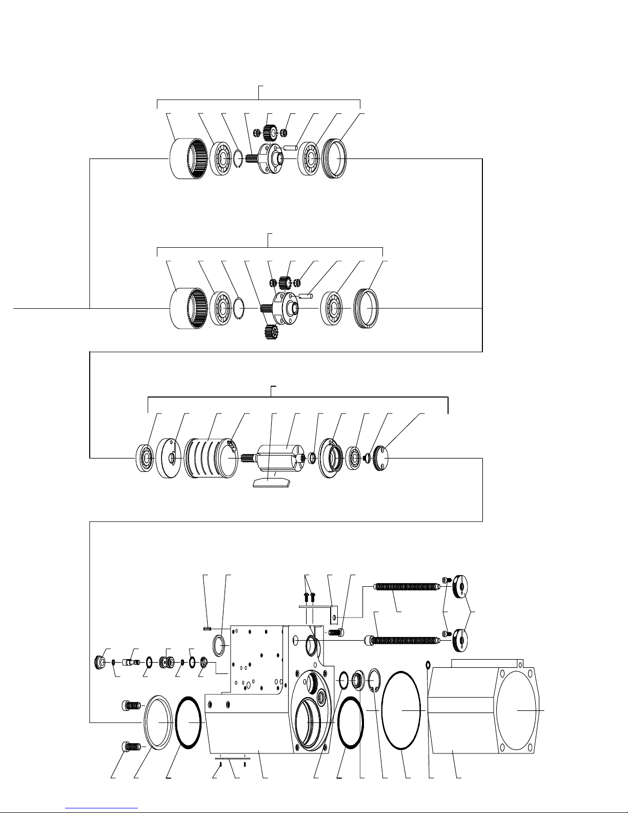
49 Spacer 33711.............................
50 Bearing (2 req’d) 33704.....................
51 Shaft (2 req’d) 40841.......................
52 Bearing (4 req’d) 42271.....................
53 Gear (2 req’d) 46417.......................
54 Spindle 49368.............................
55 Gear 34574...............................
56 Snap Ring 40842..........................
57 Ring Gear 49301...........................
58 Gearing Assembly 4.0:1 ratio 49269..........
59 Gear (2 req’d) 46416.......................
60 Spindle 49305.............................
61 Snap Ring 40843..........................
62 Gearing Assembly 7.43:1 ratio 49270.........
63 Spindle 49367.............................
64 Ring Gear 49300...........................
65 Paired Bearing 33235......................
66 Paired Spacer 44900.......................
67 Gearing Assembly 4.0:1 ratio 49271..........
68 Spindle 49304.............................
69 Gearing Assembly 7.43:1 ratio 49272.........
70 Splined Driver 34488.......................
71 Gearing Assembly 1:1 ratio 49273............
72 Spacer 49759.............................
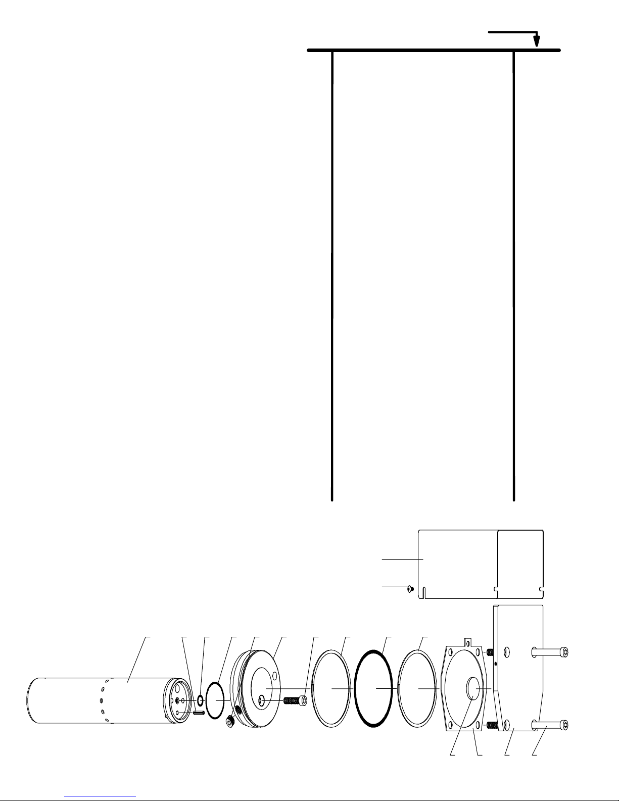
73 Torque Arm
for models FA104A--011 thru --015 04560041.....
for all other models 49345..................
74 Cap Screw
for models FA072A--( ) Y154--33...............
for models FA104A--( ) 49281...............
75 Key 49264................................
76 Seal 37389................................
77 Lock Nut 49299............................
78 Nut 49302................................
79 Adapter
3/8”--24 UNF--2B thread 49303--1..............
1/2”--20 UNF--2A thread 49282..............
#33 Jacob’s taper 49274...................
9/16”--18 UNF--2B thread 49303--2.............
Collet 49518..............................
80 Cover
for models FA072A--( ) 49339...............
for models FA104A--( ) 49362...............
81 End Cap 49338............................
82 Screw (4 req’d) Y211--11......................
83 Screw Y211--14..............................
84 Nose Housing (see pages 13 and 14)
85 Mounting Block 49350......................
86 Cap Screw (2 req’d) Y154--31..................
87 Cap Screw (3 req’d) Y99--40..................
88 Adapter (see pages 13 and 14)
89 ‘‘O” Ring (6 req’d) Y325--16....................
90 Valve Sleeve 44979........................
91 ‘‘O” Ring (5 req’d) 15066....................
92 Spool 49323..............................
93 Spring 13006..............................
94 ‘‘O” Ring Y325--16............................
95 Cap Screw 49330..........................
96 ‘‘O” Ring (2 req’d) Y325--110....................
97 Set Screw Y23--52...........................
98 Feed Tube
for models FA072A--( ) 49307--1...............
for models FA104A--( ) 49307--2...............
99 ‘‘O” Ring Y325--12............................
100 ‘‘O” Ring Y325--9............................
101 Retaining Ring Y145--8.......................
102 Seal Washer 46955........................
103 Valve Insert 49358.........................
104 Ball 44967................................
105 Spring 39679..............................
106 Retaining Ring Y147--1--K.......................
107 Spring 59342--2..............................
108 Pipe Plug Y227--2...........................
109 ‘‘O” Ring Y328--6............................
110 Washer 49349.............................
111 ‘‘O” Ring Y325--11............................
112 Insert 49327...............................
113 ‘‘O” Ring Y325--7............................
114 Meter Needle 49348........................
115 Washer 20194.............................
116 Retaining Ring Y147--50.......................
117 Cap Screw 49346..........................
118 Spacer 49359.............................
119 ‘‘O” Ring (2 req’d) Y325--11....................
120 ‘‘O” Ring (2 req’d) Y325--5....................
121 Body 49333...............................
122 Plunger 49332.............................
123 Nut 49351................................
124 Swivel Fitting (2 req’d) 59903................
125 Connector (2 req’d) 59764--004...................
126 Tube 44632--004--K...............................
127 Control Assembly
for models FA072A--( ) 49356...............
for models FA104A--( ) 49268...............
128 Retaining Ring (included with item 129)
129 Hydraulic Check Assembly
for models FA072A--( ) 49357...............
for models FA104A--( ) (includes knurled knob) 49366..
130 Adjustment Knob (models FA072A only) 49297.
131 Roll Pin (models FA072A only) Y178--114.........
132 Set Screw (models FA072A only) Y29--139.......
133 Inlet Adapter 47206........................
134 Cap Screw (10 req’d)(included with item 135) Y154--39....
135 Logic Assembly 49354......................
136 Cap Screw (6 req’d) Y154--39..................
137 Valve Assembly 49355......................
138 ‘‘O” Ring Y325--122............................
139 Cap Screw (4 req’d) Y99--40..................
140 Handle 49041.............................
141 Muffler Pad (2 req’d) 48443--1..................
142 Screen (2 req’d) 40199.....................
143 Retaining Ring (2 req’d) Y147--62...............
144 Roll Pin Y178--22.............................
145 Screen 40199.............................
146 Nameplate
for standard models 48881..................
for EU models 04334470.......................
147 Screw (2 req’d) Y60--20......................
148 Label (3 req’d)(not shown) 49530.............
149 Label (2 req’d)(not shown) 49531.............
150 Label (2 req’d)(not shown) 49532.............
151 Screen 49163.............................
152 Muffler Pad 49162..........................
153 Plate 49161...............................
154 Label (EU) (not shown) 49882...............
155 Label (EU) (3 req’d) (not shown) 04334488........
156 Label (EU) (2 req’d) (not shown) 04334496........
157 Handle Kit 49520..........................
158 Label (EU) (not shown) 49883...............
159 Motor
for models FA072A--( ) 41522...............
for models FA104A--( ) 49370...............
160 Label (EU) Direction (not shown) 49923.......

M103
85
11
TPT_1001
TPT_1002
58352--1 DIAPHRAGM (3)
59378 ”O” RING (2)
58039--1 ELEMENT INSERT (3)
58353--1 ACTUATOR
Y325--17 ”O” RING (3)
58044 SPRING (3)
58354--1 ACTUATOR (2)
58191 POPPET (2)
Y325--20 ”O” RING (3)
58031 BODY
59217 POPPET
49354 LOGIC ASSEMBLY
49316 GASKET
58193 ELEMENT INSERT (2)
49318 COVER
58336 PLATE
58337 GASKET
Y154--39 CAP SCREW (10)
59378 ”O” RING (2)
58354--1 ACTUATOR (2)
58039--1 ELEMENT INSERT
58352--1 DIAPHRAGM (3)
58353--1 ACTUATOR
59217 POPPET
49315 GASKET
58044 SPRING (3)
49320 PLATE
49317 GASKET
Y325--17 ”O” RING (3)
49321 PLATE
58191 POPPET (2)
49310 GASKET
Y325--20 ”O” RING (3)
SECTION C--C
SECTION B--B

12
49355 VALVE ASSEMBLY
Y325--11 ”O” RING (2)
49332 PLUNGER
Y147--50 RETAINING RING
Y325--5 ”O” RING (2)
49333 BODY
49267 BODY
49329--2 BUTTON
115327 SPOOL RETAINER (2)
49328 CAP SCREW
49329--1 BUTTON
20195 SPACER (4)
59632--1 PLUG
Y325--12 ”O” RING (6)
20193 SPRING (2)
20196 ”O” RING (6)
20197 SPOOL (2)
20194 WASHER (4)
TPT_1003 TPT_1004
TPT_1010
49520 ”D” HANDLE
49521 HANDLE
49159 BRACKET
49517 STUD
Y11--114--B NUT
Y211--142 SCREW (2)

M103
85
13
ADJUSTABLE NOSE HOUSING
STROKE
LENGTH
HOUSING
ASSEMBLY
NOSE HOUSING
(ITEM 84)
ADAPTER
(ITEM 88)
THREAD
(LEFT HAND)
2 INCH 49294--1 49283--1 49284 3/4”--16 UNF--2B LH
2 INCH 49294--2 49283--1 49285 1”--14 UNF--2B LH
2 INCH 49294--3 49283--1 49286 1--1/4”--12 UNF--2B LH
2 INCH 49294--4 49283--1 49287 1--1/2”--12 UNF--2B LH
2 INCH 49294--5 49283--1 49288 2”--16 UNEF--2B LH
4 INCH 49294--6 49283--2 49284 3/4”--16 UNF--2B LH
4 INCH 49294--7 49283--2 49285 1”--14 UNF--2B LH
4 INCH 49294--8 49283--2 49286 1--1/4”--12 UNF--2B LH
4 INCH 49294--9 49283--2 49287 1--1/2”--12 UNF--2B LH
4 INCH 49294--10 49283--2 49288 2”--16 UNEF--2B LH
*4 INCH 49294--11 49283--3 49284 3/4”--16 UNF--2B LH
*4 INCH 49294--12 49283--3 49285 1”--14 UNF--2B LH
*4 INCH 49294--13 49283--3 49286 1--1/4”--12 UNF--2B LH
*4 INCH 49294--14 49283--3 49287 11/2”--12UNF--2BLH
*4 INCH 49294--15 49283--3 49288 2”--16 UNEF--2B LH
85
86
84
88
THREAD
87 TPT_1005
FOR MODELS FA072A- ( ) and FA104A- ( )
*140 RPM MODELS HOUSING ASSEMBLY INCLUDES ALL ITEMS SHOWN
____________________________________________________________________________________
STRO
K
ENOSE HOUSING USED ON MODEL
S
T
R
O
K
E
LENGTH
N
O
S
E
H
O
U
S
I
N
G
(ITEM 84)
U
S
E
D
O
N
M
O
D
E
L
NUMBER
2 INCH 49514--1 FA072A--056--EU
4 INCH 49514--2 FA104A--056--EU
4 INCH 49514--2 FA104A--106--EU
4 INCH 49514--2 FA104A--226--EU
NOSE HOUSING INCLUDES ALL ITEMS SHOWN
86
85
84
TPT_1006

14
FIXED NOSE HOUSING
FOR MODELS FA072A--( ) (2” STROKE)
(EXCEPT 140 RPM MODELS)
HOUSING NOSE HOUSING THREAD
H
O
U
S
I
N
G
ASSEMBLY
N
O
S
E
H
O
U
S
I
N
G
(ITEM 84)
T
H
R
E
A
D
(LEFT HAND)
49295--1 49289 3/4”--16 UNF--2B LH
49295--2 49290--1 1”--14 UNF--2B LH
49295--3 49291--1 1--1/4”--12 UNF--2B LH
49295--4 49292--1 1--1/2”--12 UNF--2B LH
FOR MODELS FA104A--( ) (4” STROKE)
(EXCEPT 140 RPM MODELS)
HOUSING NOSE HOUSING THREAD
H
O
U
S
I
N
G
ASSEMBLY
N
O
S
E
H
O
U
S
I
N
G
(ITEM 84)
T
H
R
E
A
D
(LEFT HAND)
49296--1 49290--2 1”--14 UNF--2B LH
49296--2 49291--2 1--1/4”--12 UNF--2B LH
49296--3 49292--2 1--1/2”--12 UNF--2B LH
49296--4 49293 2”--16 UNEF--2B LH
(INCLUDES ALL ITEMS SHOWN)
THREAD 84
86
85
TPT_1007

M103
85
15

PN 49999--133
This manual suits for next models
1
Table of contents
Other ARO Drill manuals