Arrakis Systems ARC-5 User manual

ARC-5 Manual
ARC-5
Technical Manual
March 21, 2019
www.arrakis-systems.com Page 1

ARC-5 Manual
Table of Contents
Introduction..............................................................................................................................................................3
Safety Instructions...................................................................................................................................................4
Hazard / Warning Labe .....................................................................................................................................5
Identification.......................................................................................................................................................5
Warranty..............................................................................................................................................................6
Product Description.................................................................................................................................................7
Technica Description..............................................................................................................................................8
Operating Instructions..............................................................................................................................................9
Mono Mic Leve ................................................................................................................................................10
Input Channe s 1 & 2........................................................................................................................................10
Stereo Line Leve ..............................................................................................................................................11
Input Channe s 3 & 4.........................................................................................................................................11
Te ephone..........................................................................................................................................................12
Input Channe 4.................................................................................................................................................12
Contro Room....................................................................................................................................................13
Monitor System.................................................................................................................................................13
The Cue System................................................................................................................................................14
Soft Keys...........................................................................................................................................................15
Insta ation Instructions..........................................................................................................................................16
Unpacking.........................................................................................................................................................16
Before you start.................................................................................................................................................17
Step by Step ......................................................................................................................................................19
Insta ation Instructions.....................................................................................................................................19
Logic Output & Soft Keys................................................................................................................................27
Audio Ca ibration..............................................................................................................................................29
Service & Maintenance..........................................................................................................................................30
Genera Repair Considerations.........................................................................................................................30
Suggested Repair Procedures............................................................................................................................31
Opening the Conso e.........................................................................................................................................32
Rep acing S ide Faders, Switches, and other parts...........................................................................................33
Rep acing ICs....................................................................................................................................................33
Motherboard Parts Layout.................................................................................................................................34
Warranty Rep acement of Parts.........................................................................................................................35
www.arrakis-systems.com Page 2

ARC-5 Manual
Introduction
Thank you for purchasing this product by Arrakis Systems. Our company has pro ided professional
audio equipment to the broadcast, commercial audio, and consumer audio markets for more than 30
years. Our products are sold worldwide and are well known for leading edge technology, quality, and
reliability.
How to contact Arrakis Systems
Arrakis Systems inc. is located at:
Arrakis Systems inc
6604 Powell Street
Lo eland, Colorado
80538
Business Hours: 8:00am - 4:30pm mountain time
Voice: 970-461-0730 x316
Fax: 970-663-1010
Email: consolesupport@arrakis-systems.com
Ha ing difficulty contacting Arrakis?
Refer to the website (www.arrakis-systems.com) for current contact information
www.arrakis-systems.com Page

ARC-5 Manual
Safety Instructions
1. Read A Instructions. A safety and
operating instructions must be read before
operating the product.
2. Retain A Instructions. A safety and
operating instructions must be retained for
future reference.
3. Heed A Warnings. A warnings on the
product and those isted in the operating
instructions must be adhered to.
4. Fo ow A Instructions. A operating and
product usage instructions must be fo owed.
5. Heat. This product must be situated away
from any heat sources such as radiators, heat
registers, stoves, or other products
(inc uding power amp ifiers) that produce
heat.
6. Venti ation. S ots and openings in the
product are provided for venti ation. They
ensure re iab e operation of the product,
keeping it from overheating. These openings
must not be b ocked nor covered during
operation. This product shou d not be p aced
into a rack un ess proper venti ation is
provided through fo owing the
manufacturer’s recommended insta ation
procedures.
7. Water and Moisture. Do not use this
product near water—for examp e; near a
bath tub, wash bow , kitchen sink or aundry
tub; in a wet basement; or near a swimming
poo or the ike.
8. Attachments. Do not use any attachments
not recommended by the product
manufacturer as they may cause hazards.
9. Power Sources. This product must be
operated from the type of power source
indicated on the marking abe and in the
insta ation instructions. If you are not sure
of the type of power supp ied to your
faci ity, consu t your oca power company.
10. Grounding and Po arization. This
product is equipped with a po arized AC
p ug with integra safety ground pin. Do not
defeat the safety ground in any manner.
11. Power Cord Protection. Power supp y
cords must be routed so that they are not
ike y to be wa ked on nor pinched by items
p aced upon or against them. Pay particu ar
attention to the cords at AC wa p ugs and
convenience receptac es, and at the point
where the cord p ugs into the product.
12. Lightning. For added protection for this
product during a ightning storm, or when it
is eft unattended and unused for ong
periods of time, unp ug it from the AC wa
out et. This wi prevent damage to the
product due to ightning and power ine
surges.
13. Over oading. Do not over oad AC wa
out ets, extension cords, or integra
convenience out ets as this can resu t in a
fire or e ectric shock hazard.
14. Object and Liquid Entry. Never push
objects of any kind into this product through
openings as they may touch dangerous
vo tage points or short-out parts that cou d
resu t in a fire or e ectric shock. Never spi
iquid of any kind on the product.
15. Accessories. Do not p ace this product
on an unstab e cart, stand, tripod, bracket, or
tab e. The product may fa , causing serious
damage to a chi d or adu t, and serious
damage to the product. Any mounting of the
product needs to fo ow manufacturer’s
insta ation instructions.
16. A Product and Cart Combination shou d
be moved with care. Quick stops, excessive
force, and uneven surfaces may cause the
product and the cart combination to
overturn.
17. Servicing. Refer a servicing to
qua ified servicing personne .
18. Damage Requiring Service. Unp ug this
product from the wa AC out et and refer
servicing to qua ified service personne
under the fo owing conditions: a. When the
AC cord or p ug is damaged. b. If iquid has
been spi ed or objects have fa en into the
product. c. If the product has been exposed
to rain or water. d. If the product does not
operate norma y (fo owing operating
instructions). e. If the product has been
dropped or damaged in any way. f. When the
product exhibits a distinct change in
performance. This indicates a need for
service.
19. Rep acement Parts. When rep acement
parts are required, be sure the service
technician has used rep acement parts
specified by the manufacturer or that have
the same characteristics as the origina parts.
Unauthorized substitutions may resu t in
fire, e ectric shock, or other hazards.
20. Safety Check. Upon comp etion of any
repairs to this product, ask the service
technician to perform safety checks to
determine that the product is in proper
operating condition.
21. C eaning. Do not use iquid c eaners or
aeroso c eaners. Use on y a damp c oth for
c eaning.
www.arrakis-systems.com Page 4

ARC-5 Manual
Hazard / Warning Label
Identification
WARNING: SHOCK HAZARD - DO NOT OPEN
AVIS: RISQUE DE CHOC ELECTRIQUE - NE PAS OUVRIR
CAUTION: TO REDUCE THE RISK OF ELECTRIC SHOCK DO NOT
REMOVE ANY COVER OR PANEL. NO USER SERVICEABLE PARTS
INSIDE. REFER SERVICING TO QUALIFIED SERVICE PERSONNEL.
WARNING: TO REDUCE THE RISK OF FIRE OR ELECTRIC SHOCK,
DO NOT EXPOSE THE CONSOLE TO RAIN OR MOISTURE.
The Exc amation Point symbo , within an equi atera
triang e, a erts the user to the presence of important
operating and maintenance (servicing) instructions in
product iterature and instruction manua s.
The Lightning F ash With Arrowhead symbo , within an
equi atera triang e, a erts the user to the presence of
uninsu ated dangerous vo tage within the product’s
enc osure that may be of sufficient magnitude to constitute
a risk of e ectric shock.
WARNING— This equipment generates, uses and can
radiate radio frequency energy. If not insta ed and used in
accordance with the instructions in this manua it may cause
interference to radio communications. It has been tested and
found to comp y with the imits for a C ass A computing device
(pursuant to Subpart J of Part 15 FCC Ru es), which are designed
to provide reasonab e protection against such interference when
operated in a commercia environment. Operation of this equipment
in a residentia area is ike y to cause interference, in which
case the user, at his own expense, wi be required to take whatever
measures may be required to correct the interference.
www.arrakis-systems.com Page 5

ARC-5 Manual
Warranty
This console carries a manufacturer‘s warranty subject to the following guidelines and limitations:
A) Except as expressly excluded herein, Arrakis Systems inc. (“Seller”) warrants equipment of its own
manufacture against faulty workmanship or the use of defecti e materials for a period of one (1) year
from date of shipment to Buyer. The liability of the Seller under this Warranty is limited to replacing,
repairing or issuing credit (at the Seller’s discretion) for any equipment, pro ided that Seller is
promptly notified in writing within fi e (5) days upon disco ery of such defects by Buyer, and Seller‘s
examination of such equipment shall disclose to its satisfaction that such defects existed at the time
shipment was originally made by Seller, and Buyer returns the defecti e equipment to Seller’s place
of business in Lo eland, Colorado, packaging and transportation prepaid, with return packaging and
transport guaranteed.
B) Equipment furnished by Seller, but manufactured by another, shall be warranted only to the extent
pro ided by the other manufacturer.
C) Thermal filament de ices (such as lamps and fuses) are expressly excluded from this warranty.
D) The warranty period on equipment or parts repaired or replaced under warranty shall expire upon
the expiration date of the original warranty.
E) This Warranty is oid for equipment which has been subject to abuse, improper installation,
improper operation, improper or omitted maintenance, alteration, accident, negligence (in use,
storage, transportation or handling), operation not in accordance with Seller‘s operation and ser ice
instructions, or operation outside of the en ironmental conditions specified by Seller.
F) This Warranty is the only warranty made by Seller, and is in lieu of all other warranties, including
merchantability and fitness for a particular purpose, whether expressed or implied, except as to title
and to the expressed specifications contained in this manual. Seller’s sole liability for any equipment
failure or any breach of this Warranty is as set forth in subparagraph (A) abo e; Seller shall not be
liable or responsible for any business loss or interruption, or other consequential damages of any
nature whatsoe er, resulting from any equipment failure or breach of this warranty.
For the latest warranty information, please isit our website.
www.arrakis-systems.com Page 6
ARC-5 Manual
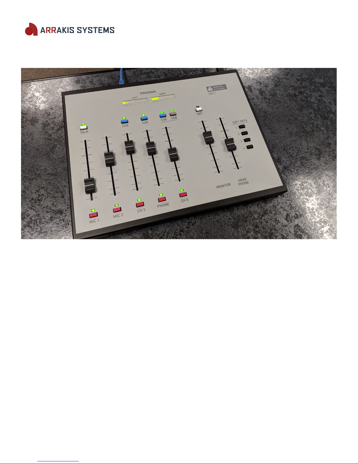
Product Description
ARC-5 Analog Broadcast Console
•5 Channels
•Inputs – 2 Mic, 1 Stereo Line, 1 USB (A/B for additional input), 1 Mix-Minus.
•Outputs – 1 Stereo Program Mixing bus.
•2 high quality mic channels (with optional 48VDC phantom power).
•2 stereo line inputs. Channel 3 & 4.
•USB input/output. Record or playback.
•Mix minus telephone output for interfacing with an external phone hybrid.
•Conducti e plastic slide faders & LED switch lamps for long life.
•4 dry contact button for connecting to 3rd party equipment, such as a studio camera system.
www.arrakis-systems.com Page 7

ARC-5 Manual
Technical Description
Mechanical
Switch type: Mechanical, 4 pole, double throw.
Switch illumination: LED, for long life.
Linear Fader type: Conducti e plastic for highest possible resolution and life. 30,000 cycles.
PC Boards: Single motherboard.
IC sockets: All IC's, except for one, are socketed for ease of ser ice.
VU Meters: Long life LED meters.
Electronic
Stereo Line Input
Freq Response- +(-).5dB 20-20kHz
S/N- -82dB typ, +8dBu in, +8 dBu out
THD- .01% typ, +8dBu in, +8 dBu out
CMRR- -75dB typ 1kHz
Max Input- +23dBu, balanced
Mono Mic Input
Freq Response- +(-).5dB 20-20kHz
EIN- -115dBu typ, -50dBu in, +8 dBu out
THD- .05% typ , -50dBu in, +8 dBu out
CMRR- -60dB typ 1kHz
Impedances
Mic Input- > 2000 ohms
Line Input- > 10000 ohms
Outputs- < 100 ohms
System
Max Output- +23dBu balanced
Stereo Separation- -75dB typ 1KHz
Cue to Pgm XTalk- -90dB typ 1KHz-75dB typ 20kHz
Power Supply
110 ac - 220 VAC, 50-60 hz, autosensing
Certified: UL, CE, CS, CB
External inline module: 3"W x 5 3/4"L x 1 3/4"D
Logic
On Air Light Logic: reed relay closure, 50mA max
Source Start Logic: Dry contact closure buttons, qty 4. Can be setup to send 5V.
Mic Turret Logic: none
www.arrakis-systems.com Page 8
ARC-5 Manual
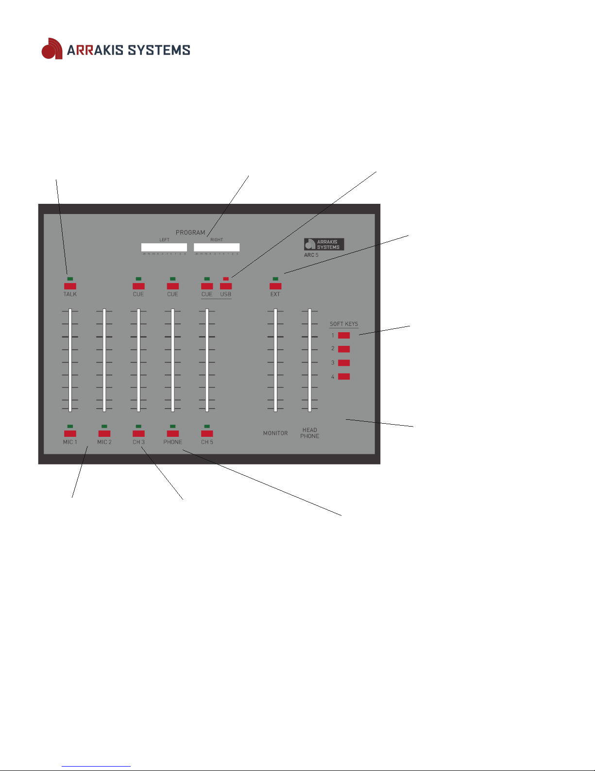
Operating Instructions
Talk Button VU Meters CH5 A/B switch
Push to talk to a caller LED meters for accurate Select between a stereo line
off line. ballistics. Program bus. Le el input and an internal USB
sound card.
EXT
Selects an external audio
input (such as off air) as the
source for the monitor &
headphone systems.
SOFT KEYS
Press to trigger a dry
contact closure. This can
control 3rd party hardware,
such as switch camera
iews.
MONITOR & HEAD PHONE
Le el Control
Slide faders to control audio
le el for Monitor &
Headphones.
Mic Channels Stereo Line Input Phone
2 Mic channels for For connecting external Channel 4 can be used as a telephone
a standard host/guest audio equipment, such as input and generates a mix-minus
format. an automation system or output to send to a phone hybrid.
MP3 player. Press the Talk switch on Mic 1 to talk to a
caller off-line. To place the caller on air,
just turn the channel on.
Channel 5 USB
The 'B' input on channel 5 is an internal USB sound card that can be utilized by a PC. This allows you to play audio from
your PC onto the board, or record audio coming from the Program output to the PC. The PC will recognize the sound card
as a 'USB Audio Codec.'
www.arrakis-systems.com Page 9

ARC-5 Manual
Mono Mic Le el
Input Channels 1 & 2
Channels 1 & 2 are both designated as mic channels. These are mic-preamps, ready to be connected to dynamic
microphones. If you are using condensor microphones, then you will need the ARC-48V Phantom Power supply, which can
be purchased on our website.
Channel On & Off
To turn the channel on, simply push the red on switch at the bottom of the fader. When the channel is on, the LED will be
lighted. To turn the channel off, simply push the red on button again.
Channel On & Off Mute Monitor
Mic channels are programmed to mute the Monitor speakers when acti ated (Monitor output). This pre ents audio
feedback through the mic channel. Audio may still be heard through the headphone output.
TALK
This button acti ates a bi-directional off air talkback between mic one and the channel 4 phone input if an external hybrid
is connected. The mic feeds the caller while the caller feeds the console cue system. The caller is heard on the monitor
speakers and in the headphones. The switch is a push-push interlocking type. Push once for on, push again for off.
TALK Button
Slide Fader Le el control
Channel ON/OFF
www.arrakis-systems.com Page 10


