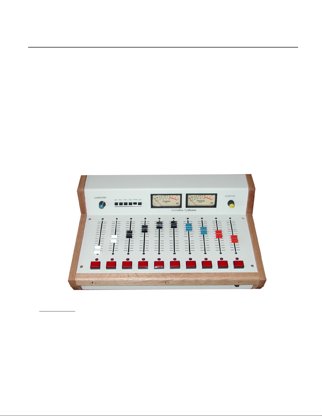
Arrakis Systems Innovation Series User manual

Arrakis Systems inc. Voice 970-461-0730 web www.arrakis-systems.com
NOVA 10C Radio Console
Innovation Series
Product Manual
Professional Radio console for On Air, Production, News, and more...
A digital console that supports BOTH analog and digital Sources
Optimized for ease of Installation of Consumer type audio Sources
High Reliability Design with P&G faders & 5 million operation On-off switches,
Rugged chassis with 1/8" hardened aluminum panels and solid oak
Powerful Telephone talk show system built in for 2 callers
Includes Source control logic, muting, talkback, and much more...
Rev 1.0 6-24-2002
The INNOVATION series of radio consoles are designed for high quality radio
broadcast applications where consumer type audio sources are used. Todays
consumer audio source equipment is extremely
high performance and inexpensive. In many
applications, it provides a professional alter-
native to the traditional balanced, high out-
put, professional console and sources.
Consumer sources such as CD play-
ers easily plug in for installation
and are so inexpensive
that they are simply
replaced when they
wear out.
The INNOVATION
series features RCA connec-
tors so that consumer source
equipment just plugs in. Traditional
broadcast source equipment is connected
as before. For very high professional quality,
INNOVATION series consoles are digital on the
inside with a mix of analog and digital source inputs. For
the flexibility to be used in any level of application, these con-
soles feature BOTH analog and digital program outputs. With
professional quality components and hardware throughout, the INNOVATION
series is ideal for professional Radio applications.

About this Manual
I- Important Information
Arrakis Systems inc. Voice 970-461-0730 web www.arrakis-systems.com
Thank you for purchasing this product by Arrakis Systems inc. Our company has
provided professional audio equipment to the broadcast, commercial audio, and
consumer audio markets for more than 20 years. Our products are sold world-
wide and are well known for leading edge technology, quality, and reliability.
Thank you from Arrakis Systems inc.
Arrakis Systems inc. is located at Arrakis Systems inc
6604 Powell Street
Loveland, Colorado
80538
Business Hours: 8:00am - 4:30pm mountain time
Contact: Voice: 970-461-0730
Fax: 970-663-1010
email: supp[email protected]
web: arrakis-systems.com
1-900 Tech support: 1-900-933-8324
Having difficulty contacting Arrakis?
Refer to the website (www.arrakis-systems.com)
for current contact information
How to contact Arrakis Systems

Arrakis Systems inc. Voice 970-461-0730 web www.arrakis-systems.com
Table of Contents
Product Description
Operating Instructions
Installation & Calibration
Repair
Maintenance
Factory Service
Warranty and License Agreement
Appendices
Sections
1.0
2.0
3.0
4.0
5.0
6.0
7.0
8.0

About this Manual
Important Information
Arrakis Systems inc. Voice 970-461-0730 web www.arrakis-systems.com
Any electronic product contains potentially lethal voltages and currents and should be serviced by
trained and experienced personnel only. Any installation, test, or calibration procedures in this
manual that require access to the interior of the equipment should be performed by qualified per-
sonnel only.
Danger- Shock & other hazards
Arrakis Systems warrants our electronic products against defects in materials and workmanship.
Arrakis Systems does not take responsibility for warranty repairs to products that have been
improperly installed, operated, or serviced. Under no circumstances is Arrakis Systems responsi-
ble for 3rd party installation, service, or other expenses. (for details refer to Section 7- Warranty
and License Agreement)
Important- Limits to Warranty & License
Pursuant to Part 15 of the FCC rules, as appropriate to the specific Arrakis product, the said
product has been designed and tested to comply with the limits of a class A digital device.
Class A digital devices- Radio Frequency Interference
Specifications, features, and function are subject to change without notice.
Product changes

Product Description
PRODUCT DESCRIPTION
Section 1
1.0 Product Features
Arrakis Systems inc. Voice 970-461-0730 web www.arrakis-systems.com
Easier to install than a home stereo system...
Optimized for inexpensive Consumer sources... such as CD players, DAT, MD, etc
A digital console on the inside... connects to analog & digital sources on the outside
Professional quality... P&G slide faders, 5 million operation on/off switches
Rugged broadcast design... 1/8" hardened aluminum, epoxy finish, & solid oak trim
10 mixing channels... more mixing power than you need & featuring full source logic control
2 channels are either analog microphone or stereo line level channels
4 channels are analog stereo line level only
2 channels are either analog telephone hybrid or stereo line level channels
2 channels are either digital input channels or stereo line level channels
Program & Record mixing buses... have BOTH analog and digital outputs
Control Room Monitor, Headphone, & Cue outputs
Talkback input & output with logic for inter-studio communication
DESCRIPTION
The INNOVATION series of radio consoles are designed for high quality radio broadcast applications where
consumer type audio sources are used. Todays consumer audio source equipment is extremely high perfor-
mance and inexpensive. In many applications, it provides a professional alternative to the traditional bal-
anced, high output, professional console and sources. Consumer sources such as CD players simply plug
in for installation and are so inexpensive that they are simply replaced when they wear out. The INNOVA-
TION series features RCA connectors so that consumer source equipment just plugs in. Traditional broad-
cast source equipment is connected as before. For very high professional quality, INNOVATION series con-
soles are digital on the inside with a mix of analog and digital source inputs. For the flexibility to be used in
any level of application, these consoles feature BOTH analog and digital program outputs. With professional
quality components and hardware throughout, the INNOVATION series is ideal for professional Radio appli-
cations.

Product Description
PRODUCT DESCRIPTION
Section 1
1.1 Physical Views
Arrakis Systems inc. Voice 970-461-0730 web www.arrakis-systems.com
REAR VIEW
Mic XLR
connectors
DC power connector
for external supply
RCA audio
connectors
Logic
Connectors
Control Room
Monitor Level
Earphone
Level
Monitor & Earphone
Selector Switch
Program VU meters
Penny & Giles
Channel Faders
5 million operation
Channel On / Off
Switches
Channel ON
LEDs
Headphone Jack
Solid Oak
Trim
1/8" Hardened Aluminum Panels
with 2 part Epoxy Paint
TOP VIEW
The NOVA-10C is durable, flexible, and compact.
The connectorized rear panel makes the NOVA-10C
well suited for mobile and remote applications as
well as for use in fixed studios.

Product Description
PRODUCT DESCRIPTION
Section 1
1.1 Physical Views
Arrakis Systems inc. Voice 970-461-0730 web www.arrakis-systems.com
AC POWER SUPPLY
The console is powered by
an external, regulated power
supply. The supply simply
plugs into the back of the
console. There are no high
voltages within the console
INTERIOR VIEW
The console top panel removes
with four screws to provide
access to the interior of the con-
sole.

Product Description
PRODUCT DESCRIPTION
Section 1
1.1 Physical Views
Arrakis Systems inc. Voice 970-461-0730 web www.arrakis-systems.com
CLOSE UP OF MOTHERBOARD
The NOVA console uses a single
motherboard for all electronic circuit-
ry. Most ICs are socketed as appro-
priate for field replacement. All panel
controls are plug in for modular
replacement.
CLOSE UP OF SLIDE FADERS
The NOVA console uses Penny
and Giles slide faders for high reli-
ability. The faders are conductive
plastic for long life and low fader
noise. The slide faders are plug in
for ease of cleaning and replace-
ment.

Product Description
PRODUCT DESCRIPTION
Section 1
1.2 Basic Specifications
Arrakis Systems inc. Voice 970-461-0730 web www.arrakis-systems.com
Stereo mixing channels 10
INPUTS
Total Inputs 10
Input Expansion unlimited, analog or digital routing switcher
Input Assignments- (single input per channel)
Channels 1 & 2- Mono mic or analog Stereo line (–10dBu, unbalanced)
Channels 3,4,5,6 analog Stereo line (–10dBu, unbalanced)
Channels 7 & 8 Telephone input or analog Stereo line (–10dBu, unbalanced)
Channels 9 & 10- Digital (S/PDIF) or analog Stereo line (–10dBu, unbalanced)
Digital inputs feature sample rate converters
Logic remote channel on / off / tally,
source start / stop, (open collector to ground)
OUTPUTS
Program Main output buss (both Digital S/PDIF & analog –10dBu unbalanced)
Audition Software assignable (both Digital S/PDIF & analog –10dBu unbalanced)
Telephone Mix minus two, mono, analog
MONITORING
Control Room Monitor stereo, -10dBu, unbalanced
Headphones stereo, unbalanced, drive hi-Z headphones to +24dBm
Cue Auto-cue into Control room monitors and Headphones
Cue out- stereo, -10dBu, unbalanced
TALKBACK unbalanced line input to Cue system, logic closure to activate
unbalanced line output from Channel 1 mic plus tally logic, with logic out
MUTING LOGIC programmable, open collector to ground
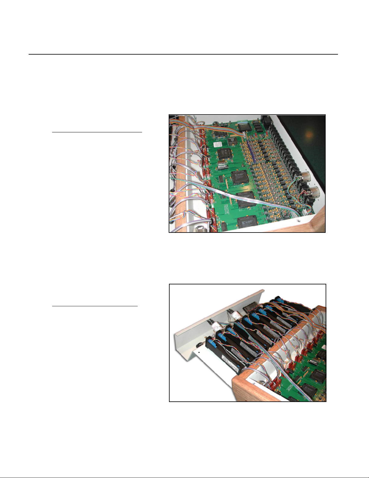
ELECTRONIC SPECIFICATIONS
POWER External, regulated, power module, UL & CE rated, 90-140VAC
SIZE 18 1/2" wide, 6 1/4" high, 12" deep
WEIGHT 23 lbs (shipping)
PHYSICAL SPECIFICATIONS
Warranty- 1 year parts and factory labor
product series- INNOVATION, model- NOVA-10C
Back Panel
Mic 2Mic 1
Left
Right
1 2 3 4 5 6 7 8 9 10 Ext DOUT
TB
OUT
LOGIC IO RS232
P A MN HP Q PH
OUTPUTS
DC
POWER
All specifications are subject to change without notice
1
23
LOGIC IO LOGIC IO
DIN
TB
IN
2 1
A P
1
2

Operating Instructions
blank page
Arrakis Systems inc. Voice 970-461-0730 web www.arrakis-systems.com

Operating Instructions
OPERATING INSTRUCTIONS
Section 2
Arrakis Systems inc. Voice 970-461-0730 web www.arrakis-systems.com
Program VU meters
CHANNEL ON/OFF
push once for On
and again for Off.
The Channel On
led will be lit when
then channel is on.
Channel ON
LEDs
HEADPHONE JACK
high impedance
headphones only
HOW TO CUE A CHANNEL
with the channel off,
pull the fader to the bottom,
then “Double-click” on the
On/off switch. The On led
will flash indicating you are
in cue. To exit cue, simply
click on the On/off switch
again or bring the fader
up from the bottom. Cue will
be heard in the monitor and
earphone systems
EARPHONE VOLUME
adjusts the level of the
earphone output
CHANNEL VOLUME
adjusts the level of the
individual channel.
MONITOR VOLUME
adjusts the level of the
control room monitor
output. Mutes when the
Control room mic is on.
MONITOR SELECT SWITCH Selects the audio input for the Monitor and Earphone systems.
EXT- selects the External Monitor Input (example- an off air monitor)
PGM- selects the console Program bus to monitor the main output of the console
AUD- selects the Audition (Record) bus and sets up an off-line mix for Phones 1&2 (refer to Phone operation)
PH2- selects the Phone 2 caller. The Phone 2 caller hears the control room mic (refer to Phone operation)
PH1- selects the Phone 1 caller. The Phone 1 caller hears the control room mic (refer to Phone operation)
OFF- no input selected
HOW TO ACTIVATE MIC TALKBACK
If channel 1 is set up as a mic channel,
then “Double-click” on the On/off switch
while the fader is down to activate the
talkback circuit. To exit talkback mode,
simply click on the On button again or
bring the fader up from the bottom.
2.0 Quick Start
The NOVA console is designed to be very easy to use. The phone system is extremely powerful and is automati-
cally set up based on your selection on the Monitor Select Switch. Refer to the section on operation of the “Pho-
ne System” for details.

Operating Instructions
OPERATING INSTRUCTIONS
Section 2
2.1 Mono Mic Level Input Channels
Arrakis Systems inc. Voice 970-461-0730 web www.arrakis-systems.com
Channels one and two can be setup as either mono
microphone channels or stereo line level channels.
OPERATION AS A MIC CHANNEL
To turn a channel on, simply push the red on switch at
the bottom of the fader. When the channel is on, the red
LED above the switch will be lighted. To turn the channel
off, simply push the red on button again
TALKBACK
Talkback is a simple 2 way intercom system to communi-
cate with another studio such as News or Production.
The NOVA has an audio output from the control room
microphone that can be connected into a console in
another studio. The NOVA has an audio input into the
cue system for the other studio to talk to the NOVA con-
sole.
The channel one mic is the talkback microphone. To acti-
vate talkback, bring the slide fader all of the way down
and then “double-click” on the channel on button. The
red LED will begin flashing to indicate that the micro-
phone is on and can be heard out the talkback output to
another studio. To exit the talkback mode, click on the on
button again or bring the slide fader up from the off posi-
tion.
CHANNELS ONE AND TWO
CAN BE SET UP AS EITHER
MONO MICROPHONE CHANNELS
OR STEREO LINE LEVEL CHANNELS
Channel
On LED
Channel
On switch

Operating Instructions
OPERATING INSTRUCTIONS
Section 2
2.1 Stereo Line Level Input Channels
Arrakis Systems inc. Voice 970-461-0730 web www.arrakis-systems.com
Channels three through ten are stereo high level input channels. Channels 7 & 8 may be optionally set up as tele-
phone hybrid inputs or as normal stereo high level sources. Channels 9 & 10 may be optionally set up as either ste-
reo high level analog or digital audio sources.
CHANNEL ON AND OFF
To turn a channel on, simply push the red on switch at the bottom of the fader. When the channel is on, the red
LED above the switch will be lighted. To turn the channel off, simply push the red on button again
CUE
To activate cue, bring the slide fader all of the way down and then “double-click” on the channel on button. The red
LED will begin flashing to indicate thatthe channel is in the cue mode. To exit the cue mode, click on the on button
again or bring the slide fader up from the off position.
Cue audio will be heard in the Monitor output and the Headphones. In the monitor output, autocue will dim the Pro-
gram on the monitors and play the cue audio over top of program audio.
Channel
On LED
Channel
On switch
CHANNELS 3-10 ARE
STEREO LINE LEVEL CHANNELS
CHANNELS
1 & 2 CAN
BE SET UP AS
MONO MIC
OR AS STEREO
LINE

Operating Instructions
OPERATING INSTRUCTIONS
Section 2
2.2 The Control Room Monitor System
Arrakis Systems inc. Voice 970-461-0730 web www.arrakis-systems.com
The Control Room Monitor system is the main audio monitoring system for the studio. It features an input selector
switch and a volume level control. The output of the monitor system is connected to an external audio power ampli-
fier and speakers. The level control on the external amplifier should be set for the maximum sound level desired in
the studio.
AUTOCUE
The NOVA console features Autocue. Whenever a channel is placed into cue, the audio in the Monitor system will
dim and the Cue audio will play over the Program signal. A system with Autocue does not require separate cue
speakers.
TALKBACK
When talkback logic is activated from another studio, then Auto-cue is activated, Monitor program audio is dimmed,
and the audio from the Talkback input is placed into the Monitor system for intercom.
MONITOR MUTING
When the control room microphone is turned on, the monitor system will mute (audio is turned off) so that there will
not be feedback from the speakers to the microphone.
MONITOR SELECTOR SWITCH
This switch selects the audio source for the Monitor system.
1) EXT- this is usually an off air audio feed to monitor the actual transmitted signal
2) PGM- the main Program output bus from the console
3) AUD- refer to “Phone system”, this is an off line phone mix of multiple channels
4) PH2- refer to “Phone system“, this is a clean feed of Caller 2 and the Control room mic
5) PH1- refer to “Phone system“, this is a clean feed of Caller 1 and the Control room mic
6) OFF- no audio source selected
OFF PH1 PH2 AUD PGM EXT
CONTROL ROOM
MONITOR LEVEL
CONTROL
MONITOR SELECTOR SWITCH

Operating Instructions
OPERATING INSTRUCTIONS
Section 2
2.3 The Headphone System
Arrakis Systems inc. Voice 970-461-0730 web www.arrakis-systems.com
OFF PH2 PH1 AUD PGM EXT
HEADPHONE
LEVEL
CONTROL
MONITOR SELECTOR SWITCH
The Headphone (earphone) system in the NOVA console is provided so that audio can be listened to while the
microphone is active and the speakers are muted. The Headphone system receives the same audio feed as the
Monitor system but does not mute when the microphone channel is turned on. The Headphone system has a jack
on the front of the console and a separate output for use with an external headphone power amp. The headphone
amplifier connected to the headphone jack is designed to work with high impedance (not 8 ohm) only.
AUTOCUE
The NOVA console features Autocue. Whenever a channel is placed into cue, the audio in the Headphone system
will dim and the Cue audio will play over the Program signal.
TALKBACK
When talkback logic is activated from another studio, then Auto-cue is activated, Headphone program audio is
dimmed, and the audio from the Talkback input is placed into the Headphone system for intercom.
MUTING
The headphone system is not muted. When the control room microphone is turned on, the Monitor system will
mute (audio is turned off) so that there will not be feedback from the speakers to the microphone. The headphone
system can not have audio feedback so that muting is not required.
MONITOR SELECTOR SWITCH
This switch selects the audio source for the Headphone (& Monitor) system.
1) EXT- this is usually an off air audio feed to monitor the actual transmitted signal
2) PGM- the main Program output bus from the console
3) AUD- refer to “Phone system”, this is an off line phone mix of multiple channels
4) PH2- refer to “Phone system“, this is a clean feed of Caller 2 and the Control room mic
5) PH1- refer to “Phone system“, this is a clean feed of Caller 1 and the Control room mic
6) OFF- no audio source selected

Operating Instructions
OPERATING INSTRUCTIONS
Section 2
2.4 The Cue System
Arrakis Systems inc. Voice 970-461-0730 web www.arrakis-systems.com
The cue system is designed for monitoring an audio source without placing it on air. This feature is useful for listen-
ing to a network feed before bringing it to air, listening to a CD to be certain it is the correct song, etc.
ACTIVATING CUE
To activate cue, bring the slide fader all of the way down and then “double-click” on the channel on button. The red
LED will begin flashing to indicate thatthe channel is in the cue mode. To exit the cue mode, click on the on button
again or bring the slide fader up from the off position.
CUE AUDIO
Cue audio will be heard in the Monitor output and the Headphones. In the Monitor and Headphone systems,
Autocue will dim the Program on the monitors and play the cue audio over top of program audio.
EXTERNAL CUE AMP AND SPEAKERS
In set up, the Autocue feature can be defeated. In this case, the console has a line level steero cue output to feed
an external cue amp and speakers.
The Channel On
LED will flash
when Cue is
activated
“Double Click” the
On switch to
activate Cue

Operating Instructions
OPERATING INSTRUCTIONS
Section 2
2.5 The VU meters
Arrakis Systems inc. Voice 970-461-0730 web www.arrakis-systems.com
The NOVA-10C console features a single
main Program bus and a single set of fixed
VU meters.

Operating Instructions
OPERATING INSTRUCTIONS
Section 2
2.6 The Telephone Talk Show System
Arrakis Systems inc. Voice 970-461-0730 web www.arrakis-systems.com
FEATURES
Advanced system supports Two Callers
Two Mix-minus buses, one for each caller
Console logic controls both hybrids
Console Audition bus auto-configures for Recording Off-line and Live mixes
Phone Modes are set by the Monitor Selector switch
BASIC SETUP
The NOVA console supports a maximum of two callers. During setup, channels 7 & 8 can be configured as tele-
phone hybrids or as standard stereo sources. Depending on your setup, you may have one, two, or no telephone
channels.
BASIC OPERATION
The console has both on air and off air mixes for live and recorded telephone operation. The main Program bus is
the output for live mixes. The console also has a Record output bus (Audition), that reconfigures based on the
Monitor Selector Switch for the specific type of talk operation you have selected.
ON AIR MIX (Monitor Selector in PGM or EXT)
The on air live mix is generated from the Program bus as you would with any other source. The external hybrid is
turned on by placing the hybrid channel in cue or turning the channel on. The hyrbrid (caller) is disconnected when
the channel is turned off. Adjust the slide fader to control caller level.
For normal operation, you cue the caller by placing the channel into cue (fader down and double-click the
on button). This turns the hybrid on so that the caller is heard off line in the cue system. To talk off line to the caller,
simply cue the control room mic (ch 1). To place the caller on air, fade the caller up. To take the caller off air, turn
the hybrid channel off by pushing the channel on button again. The caller can also be taken directly to air without
cueing by turning the channel on. Turning the channel off again disconnects the caller.
The output for Recording is the console Audition bus. In this case, the record output mirrors the Program
bus to record the complete live feed.
OFF PH1 PH2 AUD PGM EXT
MONITOR SELECTOR SWITCH
In this mode, caller one will hear everything on
the Program bus (including caller 2) “minus” himself.
Similarly, caller two will hear everything on the Pro-
gram bus (including caller 1) minus himself.
IMPORTANT
All hybrids are turned off and all call-
ers are disconnected whenever a dif-
ferent position on the Monitor Selec-
tor Switch is pushed.
When changing position on
the Monitor Select switch, it is
assumed that you are changing
modes and the system reconfigures
completely for the new mode.

Operating Instructions
OPERATING INSTRUCTIONS
Section 2
2.6 The Telephone Talk Show System (continued)
Arrakis Systems inc. Voice 970-461-0730 web www.arrakis-systems.com
OFF PH1 PH2 AUD PGM EXT
MONITOR SELECTOR SWITCH
PH1 (Off-line Record of only the Caller and Mic)
This mode is entered by pushing PH1 on the Monitor Select Switch. When pushed, the selected hybrid will be
turned on. The mic channel and caller channel LEDs will flash as indicators. The mode is exited by pushing any
other Monitor Select Switch position and the caller hybrid will be turned off.
In this mode, the selected caller will automatically hear the control room mic (ch 1) at an in hand volume
level no matter where the mic fader is set or if the mic channel is on. The selected caller will be audible in the cue
system no matter where the caller fader is set or if the channel is on.
The output for Recording is the console Audition bus. In this case, the record output will have the control
room mic on the left output and the caller on the right output. This creates a clean recording for later mixing or edit-
ing.
PH2 (Off-line Record of only the Caller and Mic)
same as PH1 except for caller and hybrid 2.
AUD (Off-line Record of all channels in Cue for use in Contest type calls)
This mode is entered by pushing AUD on the Monitor Selector Switch.
To place a caller on the cue bus, pull the fader down to the bottom and “double-click” the on button. The
channel on LED will flash. Both callers can be placed on the cue bus in the same way. To exit the cue bus, move
the fader up. The callers and any other sources in cue will all be mixed onto the cue bus at an in hand fader setting
even though the fader is down.
Cueing the mic channel will place the mic onto the cue bus and mute audio in the Monitor speakers. The
headphones must be used to hear the cue mix.
The output for Recording is the console Audition bus. In this case, the record output is a mix of all channels
on the cue bus.
In this mode, caller one will hear everything on the Cue bus (including caller 2) “minus” himself. Similarly,
caller two will hear everything on the Cue bus (including caller 1) minus himself.
IMPORTANT
All hybrids are turned off and all callers
are disconnected whenever a different
position on the Monitor Selector
Switch is pushed.
When changing position on the
Monitor Select switch, it is assumed
that you are changing modes and the
system reconfigures completely for the
new mode.

Installation & Calibration
blank page
Arrakis Systems inc. Voice 970-461-0730 web www.arrakis-systems.com
This manual suits for next models
1
Table of contents
Other Arrakis Systems Dj Equipment manuals
Popular Dj Equipment manuals by other brands

Faderfox
Faderfox Solid Control DJ44 user manual

Equinox Systems
Equinox Systems Twin Shot MKII Electric Confetti Launcher user manual

DTS
DTS Wonder D user manual

Uplus Lighting
Uplus Lighting AZ-SPOT PR 300 user manual

Pioneer
Pioneer DDJ-SZ operating instructions

Chauvet
Chauvet EVE E-50Z Quick reference guide