Art TUBE MIX User manual

TUBE MIX
FIVE CHANNEL MIXER WITH USB
AND ASSIGNABLE 12AX7 TUBE
User's Manual

I
IMPORTANT SAFETY INSTRUCTIONS – READ FIRST
This symbol, wherever it appears, This symbol, wherever it appears, alerts
alerts you to the presence of uninsulated you to important operating and maintenance
dangerous voltage inside the enclosure. Voltage instructions in the accompanying literature.
that may be sufficient to constitute a risk of shock. Please read manual.
Read instructions:
Retain these safety and operating instructions for future reference. Heed all warnings printed here and on the equipment.
Follow the operating instructions printed in this user guide.
Do not open:
There are no user serviceable parts inside. Refer any service work to qualified technical personnel only.
Power sources:
Only connect the unit to power of the type marked on the rear panel.
Power cord:
Use the power cord with the mains plug appropriate for your local mains supply as provided with the equipment. If the
provided plug does not fit into your outlet consult your service agent. Route the power cord so that it is not likely to be
walked on, stretched or pinched by items placed upon or against.
Ventilation:
Do not position the unit where the air required for ventilation is impeded. If the unit is to be operated in a rack, case or
other furniture, ensure that it is constructed to allow adequate ventilation.
Moisture:
To reduce the risk of fire or electrical shock do not expose the unit to rain, moisture or use in damp or wet conditions. Do
not place a container of liquid on it, which may spill into any openings.
Heat:
Do not locate the unit in a place close to excessive heat or direct sunlight, as this could be a fire hazard. Locate the unit
away from any equipment, which produces heat such as: power supplies, power amplifiers and heaters.
Environment:
Protect from excessive dirt, dust, heat, and vibration when operating and storing. Avoid tobacco ash, drink spillage and
smoke, especially that associated with smoke machines.
Handling:
To prevent damage to the controls and cosmetics avoid rough handling and excessive vibration. Protect the controls from
damage during transit. Use adequate padding if you need to ship the unit. To avoid injury to yourself or damage to the
equipment take care when lifting, moving or carrying the unit.
Servicing:
Switch off the equipment and unplug the power cord immediately if it is exposed to moisture, spilled liquid, objects fallen
into opening, or the power cord or plug becomes damaged during a lightning storm or if smoke odor or noise is noted.
Refer servicing to qualified technical personnel only.
Installation:
Install the unit in accordance with the instructions printed in the user manual.

II
TABLE OF CONTENTS
IMPORTANT SAFETY INSTRUCTIONS – READ FIRST .....................................................................I
INTRODUCTION..................................................................................................................................1
OPERATION........................................................................................................................................2
Inputs and Outputs ............................................................................................................................2
Input jacks...............................................................................................................................................................2
Output jacks............................................................................................................................................................2
USB jack .................................................................................................................................................................2
Controls..............................................................................................................................................2
TRIM controls..........................................................................................................................................................2
EQ controls .............................................................................................................................................................2
AUX send controls..................................................................................................................................................3
LEVEL and PAN controls........................................................................................................................................4
CH 5 AMP SIM. switch............................................................................................................................................4
TUBE ASSIGN switch.............................................................................................................................................4
PEAK LEDs.............................................................................................................................................................4
+48V switch.............................................................................................................................................................5
METER LEDs and METER SELECT switch........................................................................................................... 5
USB RECORD LEVEL VU meters and USB SOURCE switch...............................................................................6
MAIN MIX level .......................................................................................................................................................6
AUX Return.............................................................................................................................................................6
USB Return.............................................................................................................................................................6
CONTROL ROOM section......................................................................................................................................6
USB COMPUTER SETTINGS .............................................................................................................8
APPLICATIONS ..................................................................................................................................9
Recording a track....................................................................................................................................................9
Track Bouncing.......................................................................................................................................................9
Live use................................................................................................................................................................... 9
WARRANTY INFORMATION............................................................................................................10
Limited Warranty...................................................................................................................................................10
Exclusions.............................................................................................................................................................10
Service..............................................................................................................................................11
SPECIFICATIONS.............................................................................................................................12
LIST OF FIGURES
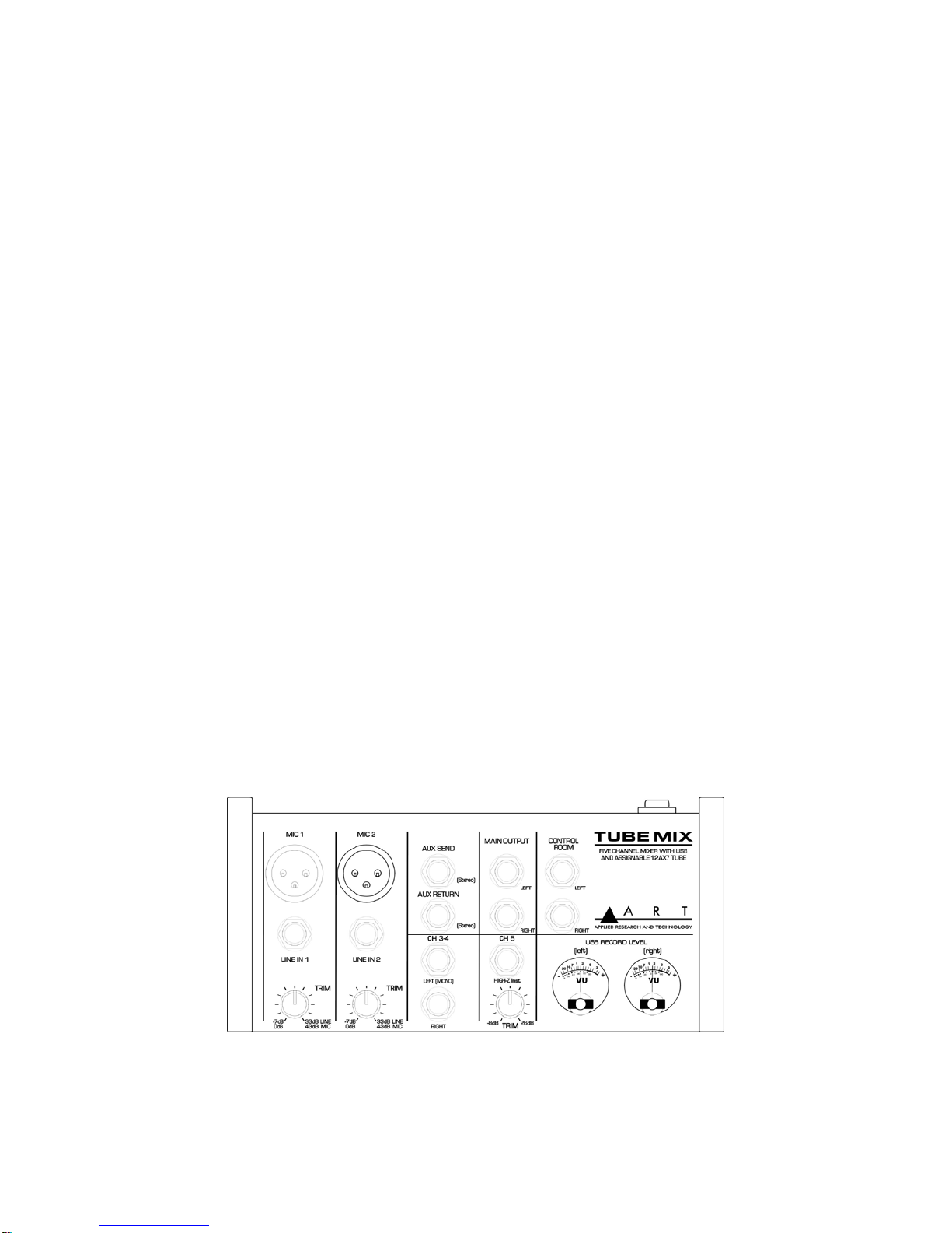
Input and Output section......................................................................................................................1
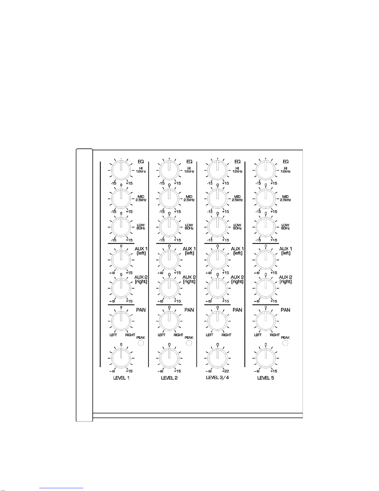
Input section.........................................................................................................................................3
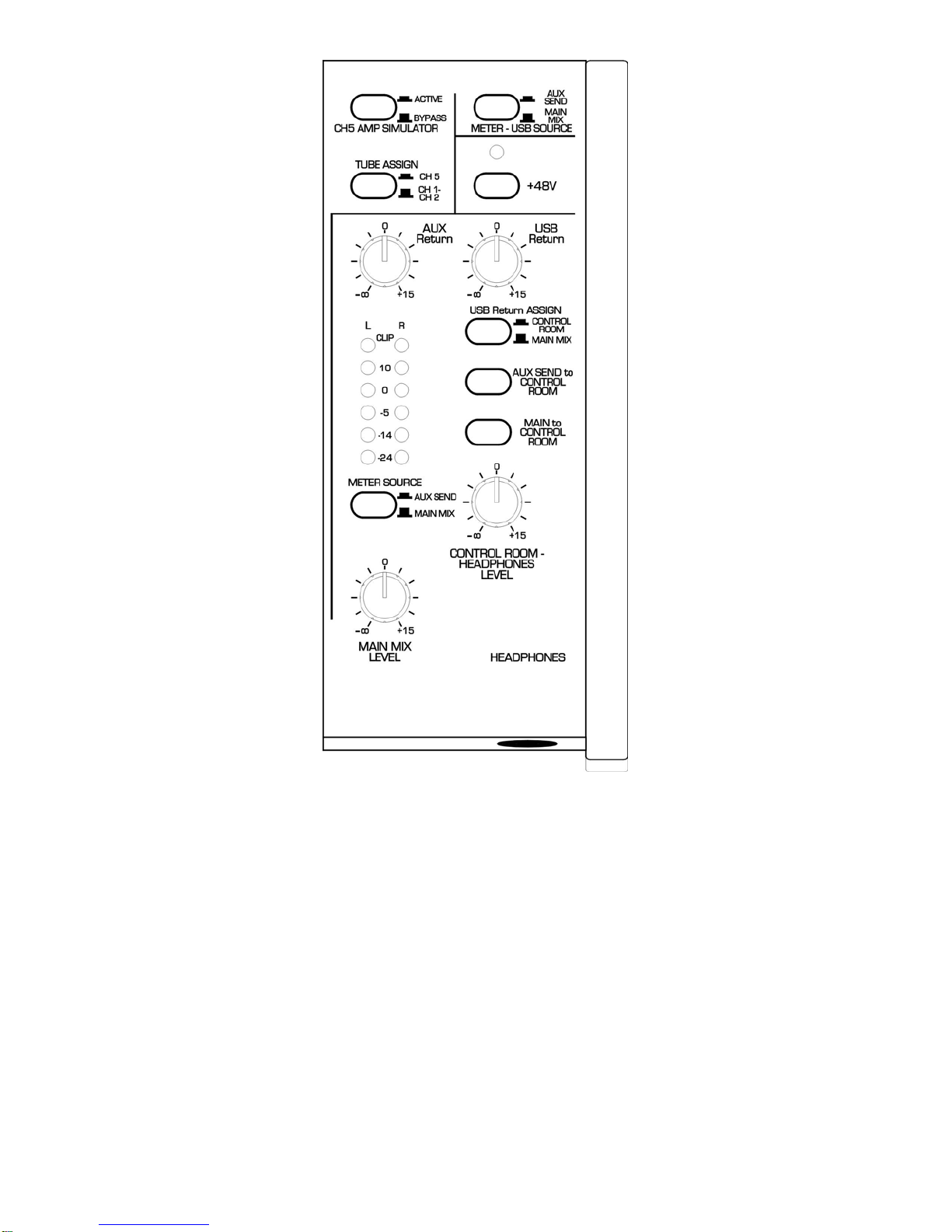
Control section.....................................................................................................................................5
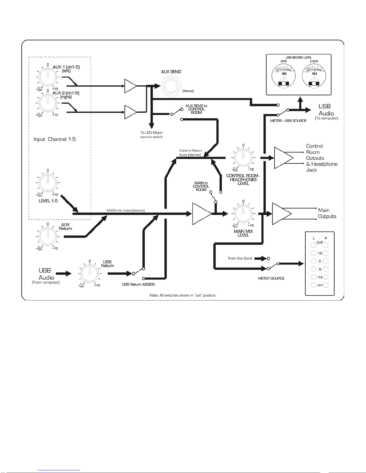
Block Diagram......................................................................................................................................7
I
INTRODUCTION
The ART Tube Mix Microphone, Instrument, and Line Mixer / Computer Interface is a compact
versatile audio interface for your computer that converts analog signals from a variety of audio
sources to a digital signal that your computer understands. It can also be used as a standalone mixer
through the main mix outputs. The Tube Mix provides a great starting point for personal home studio
recording or for anyone wanting to do mobile location recording. Use the Tube Mix to record
podcasts, capture your latest idea for a song, make voiceovers for your home movies, or record a jam
with a friend - whenever and wherever your creativity takes you!
Key Features Include:
•CH1 and CH2 microphone (balanced XLR) inputs with trim control.
•CH5 instrument/Line (unbalanced 1/4-inch TS) input with trim control.
•CH3/4 Stereo line inputs.
•CH5 High impedance Instrument input with switchable amp simulator.
•12AX7 tube can be applied to either CH1 & CH2 or CH5 (Inst. input).
•Switchable low noise +48V phantom power for microphones.
•Balanced 1/4-inch TRS inputs for stereo or mono line-level sources on CH3-4.
•1/4-inch TRS output jacks work with balanced or unbalanced lines.
•Adjustable Three band EQ on each channel.
•Two pre-fader Aux sends per input channel for live monitor mixes, effects or recording.
•Control Room section for independent monitoring.
•Stereo 1/4-inch TRS headphone jack.
•Red LED signal/clip indicator for CH1, CH2, and CH5.
•Main output level shown on LED meter display.
•Switchable assignment of USB playback to Main or Control Room output.
•Analog VU meters for separately monitoring the USB record level.
•USB 2.0 compliant.
•No special drivers needed with most modern versions of Windows, Mac OS, and Linux.
Input and Output section

2
OPERATION
Inputs and Outputs
Input jacks
CH1 and CH2 XLR inputs can only accept microphone level signals. Phantom power is present at
both inputs if the +48 switch is depressed. Use the 1/4-inch jacks for line level signals. These jacks
accept both balanced and unbalanced signals. The Trim control works on both sets of input jacks.
Caution! Do not connect a microphone with unbalanced output via XLR plug; it may be damaged by
the phantom power. To prevent switching noise, only activate or deactivate the phantom power when
the mixer is switched off or the output controls are set to “0”
Inputs 3/4 are intended for balanced or unbalanced line level signals including portable electronics. If
you only use the Left input jack only, this channel processes the mono signal the same as all of the
other input channels. When you apply a stereo signal (using both jacks), the Left channel is passed
to the Aux 1 send and the right channel is passed to the Aux 2 send. When you pan to the extreme,
the opposite channel on the Main Mix buss is faded off. CH5 input accepts a mono instrument signal.
The input impedance is high, so it will not load or dull the instrument's output. The AUX return jack is
stereo. Applying a mono plug will only apply signal to the left return channel.
Output jacks
The MAIN and CONTROL ROOM 1/4-inch jacks are balanced low impedance outputs. The AUX
SEND and HEADPHONES are stereo (Tip, Ring, Sleeve) outputs. You can control the
HEADPHONES output easily with the CONTROL ROOM-HEADPHONES LEVEL control. The AUX
SEND level is set by the sum of individual AUX send controls. It is easily monitored, by using the LED
meters for troubleshooting.
USB jack
The USB jack is a full speed interface for two channels of audio. Standard Windows and OSX drivers
will recognize this interface as soon as it is plugged in.
Controls
TRIM controls
The Trim control is adjusted to optimize the wide range of input levels possible at the XLR or 1/4-inch
jacks on CH1, CH2 and CH5. Start with the control Fully Counterclockwise (CCW). Rotate the knob
Clockwise (CW) until the Clip LED lights on peaks and back off a small amount to leave some
headroom.
EQ controls
The three-band EQ circuit processes the audio before the AUX sends. Adding too much boost may
trigger the CLIP LED on signal peaks. If this happens, reduce the TRIM control.
3
AUX send controls
The AUX send buss is used for effects sends, creating monitor mix for live use or recording to the
USB output when bouncing tracks. The AUX buss has better left/right channel isolation than the
MAIN MIX buss, so this is the preferred recording mode.
Each AUX send signal sums a pre-fader signal into the AUX send output. AUX1 will be present on the
tip of the output jack and AUX2 will be on the ring.
IF you assign the AUX send signal to the VU meters/ USB out, AUX1 becomes the left channel and
AUX 2 the right.
Input section

4
LEVEL and PAN controls
Each channel's output is sent to the Main Mix buss. The LEVEL and PAN controls adjust how much
of the signal is present on the Left and Right output. The Pan control adds a small amount of gain
between the center and the extreme position to enhance the stereo panning effect.
Note: The LEVEL control can add quite a bit of gain and the CLIP LED does NOT monitor this.
CH 5 AMP SIMULATED switch
When depressed, this switch provides a simulated guitar amp cabinet to CH 5. This processing is
located after the Tube function if the tube is assigned to CH 5.
TUBE ASSIGN switch
The Tube Mix incorporates a 12AX7 tube for adding warmth to either CH1 and CH2 or just CH5. The
tube is placed between the Trim and EQ on the channel, so you can tweak the tube character with
the EQ. The tube circuit does not add much gain. It is optimized for adding warmth, not distortion.
When the TUBE ASSIGN switch is out, the two tube sections are applied to the signal on CH1 and
CH2 after the TRIM controls. When depressed, both stages of the tube are placed in series on CH 5.
PEAK LEDs
The Peak LEDs on CH1, CH 2, and CH 5 monitor the signal level after
the EQ section to allow
adjustment of the Trim function. When lit, the signal is within 3dB of clipping.
Note: There is no PEAK LED on CH 3/4. It is possible to create clipping on this channel for very high-
level signals (> +12 dBu) if the EQ is boosted excessively. If you find yourself in this predicament, try
using the EQ to cut more.
5
Control section
+48V switch
The +48V switch applies phantom power to both XLR inputs when depressed. The LED above
indicates that phantom power is active.
METER LEDs and METER SELECT switch
The METER LEDs indicate the level present at either the MAIN output or the AUX send output. "0"
indicates 0dBu(0.775 V rms). The meters' quick response is useful for monitoring the USB output
level to prevent clipping.

6
USB RECORD LEVEL VU meters and USB SOURCE switch
The VU meters monitor the signal level present at the USB ADC. The Main mix output is selected as
a source when the switch is out. This mode is useful when recording a mix of all of the inputs. When
the switch is depressed, the AUX buss is the source for the USB output. This mode allows recording
a mix of inputs independent of the Main output.
MAIN MIX level
The MAIN MIX buss contains the summation of all of the inputs plus the AUX return signal. This
signal is present on the MAIN OUTPUT jacks and can be routed to the LED meters and control room
section through switches.
AUX Return
The AUX return level controls the signal level summed into the main mix buss. The AUX return
function is useful in adding effects like reverb to the inputs or you can use it as another pair of inputs.
USB Return
The USB return control adjusts the level of the audio returning from your computer before it is
summed into the MAIN or CONTROL ROOM buss. The USB Return ASSIGN switch sends this signal
to the MAIN buss when it is out. When depressed, it routes the USB return signal to the control room.
NOTE: it is possible to create a feedback loop if the USB return signal is routed to the USB output
while your recording program is monitoring the same USB input. To avoid this, select the AUX SEND
as a source for the USB output.
CONTROL ROOM section
The three switches above the CONTROL ROOM-HEADPHONES LEVEL control are used to select
which signals are present on the CONTROL ROOM and HEADPHONES outputs. The levels of both
outputs are controlled by this level control.
When all of the switches are out, the CONTROL ROOM output will be silent. Depress the switch
corresponding to the signal you want to monitor.
NOTE: the MAIN MIX signal in this case is "pre-fader" or unaffected by the MAIN MIX LEVEL control.
7
Block Diagram

8
USB COMPUTER SETTINGS
Once the USB connection is made and your computer is on, your computer will power the USB
interfaces circuitry over the USB bus and the unit will automatically connect and try to set your
computer “Default Audio Device” to be “USB Audio CODEC”. Usually the computer will do this
automatically whenever a USB device is first connected, but it is sometimes necessary to make the
selection manually. The same settings may need to be made in your particular audio application as
well (Check your application instructions). These settings should be made while the USB Mix and
computer are connected and powered on.
Your computer audio output “Speaker” is now set to be the “USB Audio CODEC” and playback audio
is routed to the USB Mix. This must be done while the USB Mix is connected to the computer and
powered on. If you prefer, you can have the computer output routed to your computer speakers
instead of the USB Mix monitor output jack, by selecting your computer speakers for “OUTPUT”
instead of “USB Audio CODEC” in the above setup procedures. After the above settings are made,
your computer will automatically reconfigure itself back to these settings every time the USB Mix is
reconnected to the computer. Your recording software may also select which inputs or outputs are
being used.
NOTE: The Tube Mix interface uses the standard “USB Audio CODEC”. This driver is built into most
modern operating systems, including most current versions of Linux. Since some details of how the
audio interface is set vary with different versions of Linux, the setup is beyond the scope of this
document. The main key in setup is to look for “USB Audio CODEC” as the recording source or
playback monitor output while the USB Mix is connected.

9
APPLICATIONS
Recording a track
Set the METER-USB SOURCE switch "out". Now, everything on the MAIN MIX buss will be sent to
the USB output.
Note that this is not the ideal way to isolate a track to only one output channel as the Pan depth is
less than the AUX send knob set to min, but it allows you to use the AUX send/ return for adding
effects before recording.
Use the control room output to monitor the recording and if required, the USB return.
Track Bouncing
Set Meter/USB source "IN", USB return switch to "MAIN MIX", Monitor signal level through the
Control room (headphones). Use meters to monitor the recording level, use the Aux Send knobs to
adjust the channel to record. You can also use the LEDs to monitor the record level if their switch is
set to AUX SEND (in). You can isolate the recording tracks by setting the AUX send to Control Room
switch "IN" and the Main to Control Room switch "OUT" and the USB Return Assign to Main Mix
("OUT").
Live use
With all of the switches of the control room section in the OUT position, the Tube Mix is set up for use
as a live use. The Aux buss can be used for monitor mixes and the main output will contain all of the
input channels as well as the USB return and AUX return signals. Depressing the AUX SEND to
CONTROL ROOM switch will allow you to use the CONTROL ROOM outputs as monitor outputs with
a master level control.

10
WARRANTY INFORMATION
Limited Warranty
Applied Research and Technology will provide warranty and service for this unit in accordance with
the following warrants:
Applied Research and Technology, (A R T) warrants to the original purchaser that this product and
the components thereof will be free from defects in workmanship and materials for a period of three
years from the date of purchase. Applied Research and Technology will, without charge, repair or
replace, at its option, defective product or component parts upon prepaid delivery to the factory
service department or authorized service center, accompanied by proof of purchase date in the form
of a valid sales receipt.
Exclusions
This warranty does not apply in the event of misuse or abuse of the product or as a result of
unauthorized alterations or repairs. This warranty is void if the serial number is altered, defaced, or
removed.
A R T reserves the right to make changes in design or make additions to or improvements upon this
product without any obligation to install the same on products previously manufactured.
A R T shall not be liable for any consequential damages, including without limitation damages
resulting from loss of use. Some states do not allow limitations of incidental or consequential
damages, so the above limitation or exclusion may not apply to you. This warranty gives you specific
rights and you may have other rights, which vary from state to state.
For units purchased outside the United States, an authorized distributor of Applied Research and
Technology will provide service.

11
Service
The following information is provided in the unlikely event that your unit requires service.
1. Be sure that the unit is the cause of the problem. Check to make sure the unit has power, all
cables are connected correctly, and the cables themselves are in working condition. You may
want to consult with your dealer for assistance in troubleshooting or testing your particular
configuration.
2. If you believe that the ART unit is at fault, go to www.artproaudio.com.
3. Select “Support”, then “Return Authorization Request” to request a return authorization number.
4. If you are returning the unit for service, pack the unit in its original carton or a reasonable
substitute. The original packaging may not be suitable as a shipping carton, so consider putting
the packaged unit in another box for shipping. Print the RA number clearly on the outside of the
shipping box. Print your return shipping address on the outside of the box.
5. Include, with your unit, a note with the RA number and your contact information, including a return
shipping address (we cannot ship to a P.O. box) and a daytime phone number, and a description
of the problem, preferably attached to the top of the unit. Also include a copy of your purchase
receipt.

12
SPECIFICATIONS
Max input level
CH1, CH 2 (Microphone) +9dBu
CH1, CH 2 (LINE IN) +20dBu
CH 3/4 (EQ Flat) +20dBu
CH 5 (EQ Flat) +16dBu
AUX Return +24dBu
Input Impedance
Microphone 3.5k Ohm
Line (CH1, CH2, CH 3/4) 10k Ohm
CH 5 (Inst.) 1M Ohm
Max Output level
Main, Control Room (Balanced/Unbalanced) +20dBu/+17dBu
Aux Send +20 dBu
Headphones 100mW / Ch @ 300 Ohms, 50mW /Ch @32 Ohms
Output Impedance
Main, Control Room (Balanced/Unbalanced) 150/100 Ohm
AUX out 150 Ohm
Headphones 100 Ohm
Max Gain
Microphone in to Main output (balanced) +73dB
LINE IN to Main output (balanced) +63dB
CH 5 to Main output (balanced) +56dB
CH3/4 to Main output (balanced) +30dB
Equivalent Input Noise
Microphone (@max gain) -127dBu "C" wtd.
Line (@max gain) -105dBu "C" wtd.
Instrument (@ max gain) -112dBu "C" wtd.
USB
Computer Interface USB class compliant plug-and-play Mac and PC interface
A/D, D/A 16 Bit, 44.1 kHz or 48 kHz, USB selectable from computer
0.4 ms A/D latency @ 44.1 kHz
Power supply requirements 18 VAC, 1000mA
Phantom Power Switch selectable, +48V DC, filtered, current limited
Frequency response (Microphone in to Main Out) 20-100kHz + 1dB
Mechanical
Chassis Type Steel, Painted finish
Dimensions (HWD) 3.3-inch x 7.8-inch x 10.4-inch
84mm x 198mm x 265mm
Weight (w/ Supply) 5.5 lbs. (2.5 kg)
Note: 0 dBu = 0.775Vrms
ART maintains a policy of constant product improvement. Therefore, specifications are subject to change
without notice.
Go to www.artproaudio.com for the latest information and support.

www.artproaudio.com
E-mail: support@artproaudio.com
© 2016 Applied Research & Technology/ Yorkville Sound
TUBE MIX TM-5004-101
FIVE CHANNEL MIXER WITH USB AND ASSIGNABLE 12AX7 TUBE
Table of contents
Other Art Music Mixer manuals


