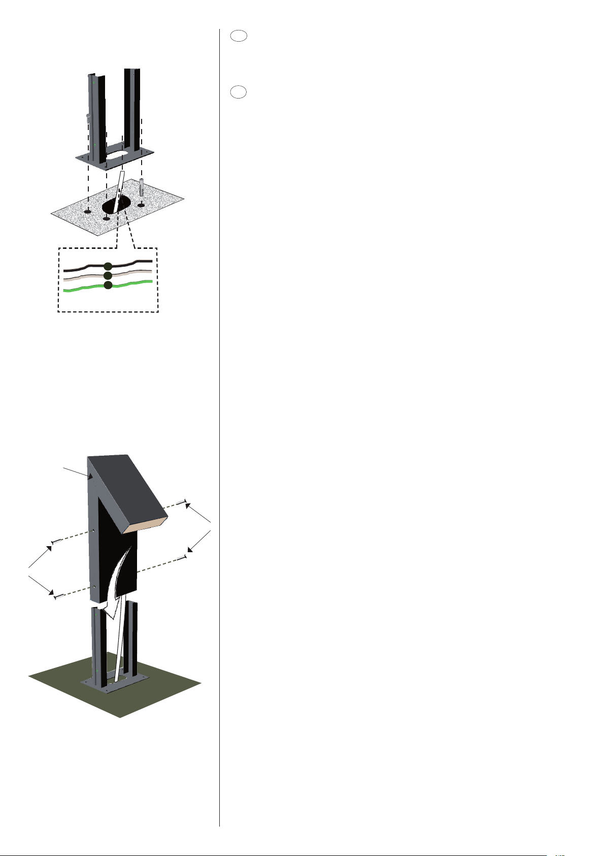
polaritè blanc / blanc, noir / noir et vert / vert avec une connexion résistant à l’eau. Placez le joint
Tenendo premuto il fermo di sicurezza H, fare scorrere il cavetto d'acciaio Ffino al segno
precedentemente marcato. Ripetere l'operazione per gli altri due cavetti d'acciaio (fig.4).
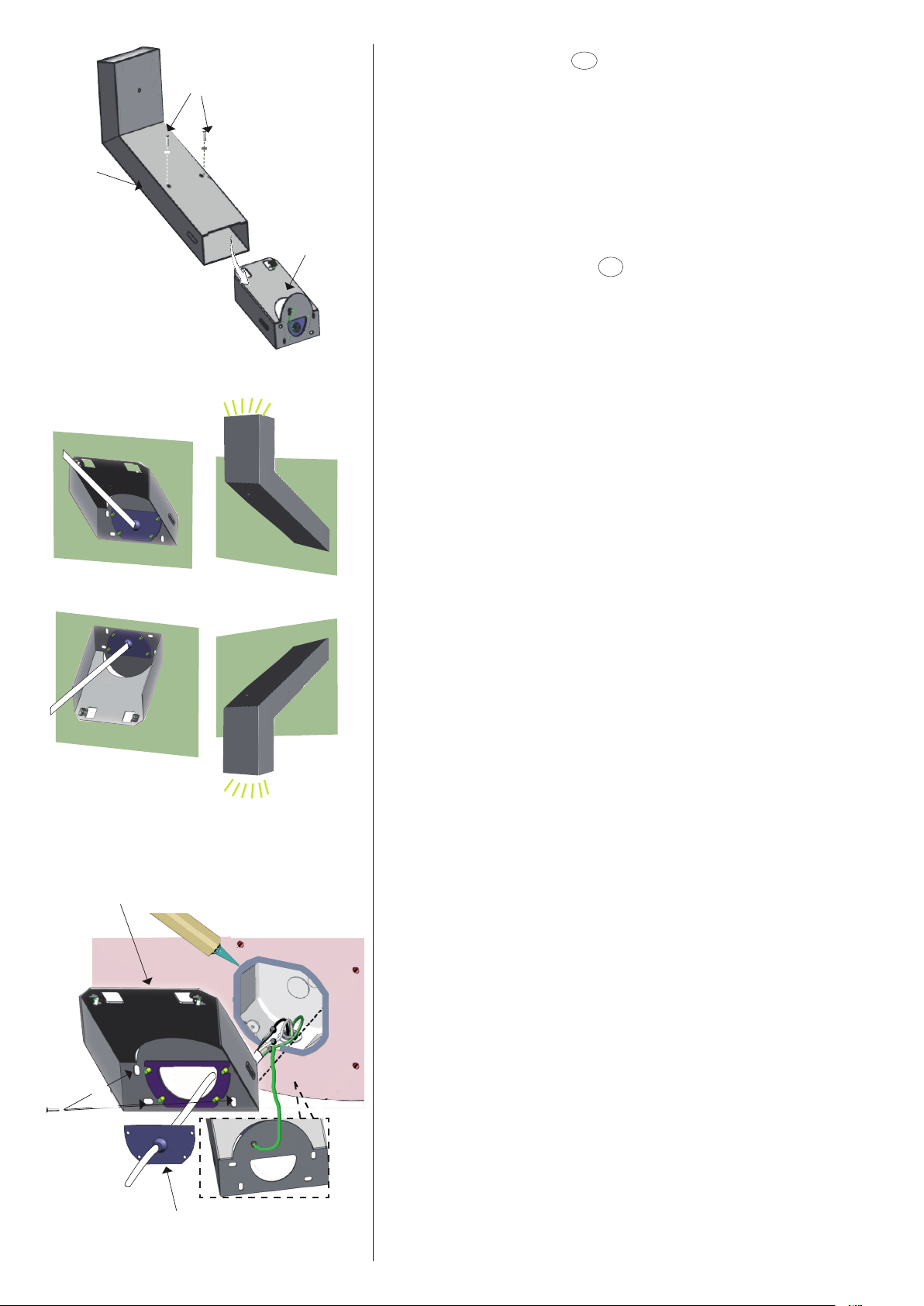
Segnare sul soffitto la posizione dei 4 fori a 90° Idel fondello B. Forare con punta di sezione
adeguata al tassello ad espansione scelto. Far passare i cavi ele ttrici provenie nti dal muro
attraverso il foro Ldel fondello Be fissare il fondello al soffitto. Posizionare la piastra Csul
fondello Battraverso le asole Me stringere le viti (fig.5).
Eseguire i collegamenti elettrici all'apposito morsetto N. Collegare il cavo di messa a terra in
corrispondenza del simbolo , facendo attenzione a inserire il cavo al di sotto della lamella
presente in corrispondenza della vite O. Se fosse necessario bilanciare l’apparecchio, allen-
tare uno dei tre fermi H, spingere il fermo verso il soffitto e far scorrere il cavo di sostegno,
riavvitare il fermo di sicurezza H(fig.6).
I
I
I
L
M
M
B
H
F
Fig.5
Fig.6
Fig.4
H
H
H
O
N
I
I
C
Presser l’arrêt de sécurité H, faire glisser le câble d’acier Fjusqu’au point marqué auparavant.
Répéter l'opération pour les deux autres câbles d’acier (fig.4).
Marquer sur le plafond la position des 4 trous de 90° Idu culot B. Percer au moyen du foret
approprié à la cheville à expansion choisie. Faire passer les câbles électriques sortant du mur
à travers le trou L du culot Bet le fixer au plafond. Positionner la plaque C sur le culot Bà
travers les trous oblongs Met serrer les vis (fig.5).
Brancher à la borne adéquate N. Connecter le câble de mise à la terre près du symbole ,
en faisant attention à insérer le câble au-dessous de la plaque présente près de la vis O. Au
cas où il serait nécessaire de balancer la lampe, desserrer un des trois arrêts H , pousser
l’arrêt vers le plafond et faire glisser le câble de support; ensuite revisser l’arrêt de sécurité H
(fig.6).
Pres s ret ainer Hand make the steel cable Fslide up to the previous mark. Repeat the
operation for the other two steel cables (fig.4).
Mark on the ceiling the position of the 4 90° holes Iof the bottom plate B. Drill with the
proper drill for the chosen screw anchor. Make the electric cables coming from the wall go
through hole Lof the bottom plate Band fix it to the ceiling. Position plate Con the bottom
plate B by means of slots Mand tighten the screws (fig.5).
Carry out the electrical connections to the proper terminal N. Connect the ground cable
near symbol , being careful to insert it under the plate located near screw O. In case the
lamp should be balanced, loosen one of the three retainers H, push the retainer toward the
ceiling and make the support cable slide, screw the retainer Hagain (fig.6).
Die Haltevorrichtung Hvon dem Kabel drück en und die Stahllitze Fbis das vorherige
Ken nzeichen gleit en lassen. Die se O peration auc h für die an deren zwei S tahllit z en
wiederholen (Abb.4).
Die Position der 4 90° Löcher Ides Bodens Bauf der Decke kennzeichnen. Mit einem Bohrer
dem gew ählten S preizdübel entsprech end durch bohren. Die aus dem Mauer kommen den
Stromkabel durch das Loch L des Bodens Bdurchlegen und ihn auf der Decke befestigen.
Positionieren Sie die Platte Cdurch die Ösen Mam Boden Bund ziehen Sie die Schrauben
fest (Abb.5).
Di e S t romk abel an die geeign e t e Klemme Nan schließe n . Das E rdungs k abe l be i dem
Symbol anschließen . Dabei darauf ac hten, dass das Kabel unter die Lamelle neben der
Schraube Ogesteckt ist. Wenn die Lampe ausgewogen werden soll, lösen Sie eine der drei
Haltevorric h tungen H, sc hie ben Sie sie an der De c ke und das Stützse il gleite n lassen,
schrauben Sie die Haltevorric htung H (Abb.6).
Manteniendo presionado el dispositivo de fijación de seguridad H, hacer deslizar el cable de
acero Fhasta alcanzar el punto marcado anteriormente. Repetir esta operación para los
demás cables de acero (fig.4).
Marcar en el techo la posición de los 4 agujeros de 90° Idel fondo B. Perforar utilizando una
punta adecuada para el tipo de taco de expansión utilizado. Hacer pasar los cables eléctricos
procedentes de la pared a través del agujero Ldel fondo B, y fijar el fondo al techo. Poner
la placa Cen el fondo Bmediante las ranuras M y apretar los tornillos (fig.5).
Efectuar las conexiones eléctricas al borne adecuado N. Conectar el cable de puesta a tierra
en correspondencia del símbolo , teniendo cuidado con poner el cable bajo la lámina en
correspon dencia del tornillo O.Si fuera necesario equilibrar el aparato, aflojar un o de los
tres dispositivos de fijación H, empujarlo hacia el techo y hacer deslizar el cable de soporte;
atornillar nuevamente el dispositivo de fijación de seguridad H(fig.6).
F
EN
D
E