8A
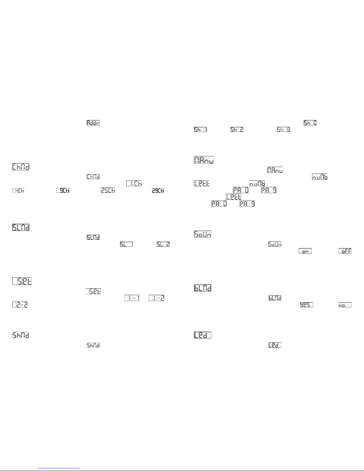
Press the MENU button up to when the is shown on the display. Pressing the
ENTER button and the display will blink. Use the DOWN and UP button to change the DMX
512 address. Once the address has been selected, press the ENTER button to setup or
automatically exit menu mode without any change after 60 seconds. Back to the previous
functions without any change press the MENU button.
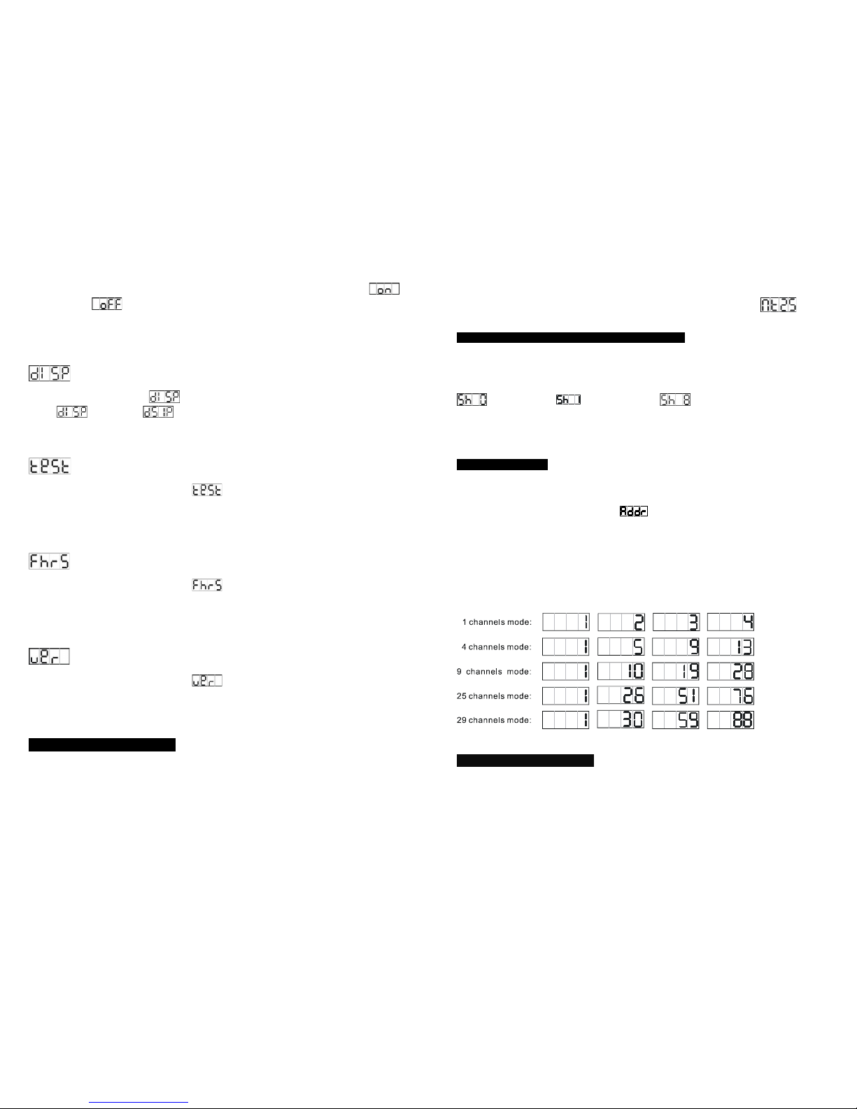
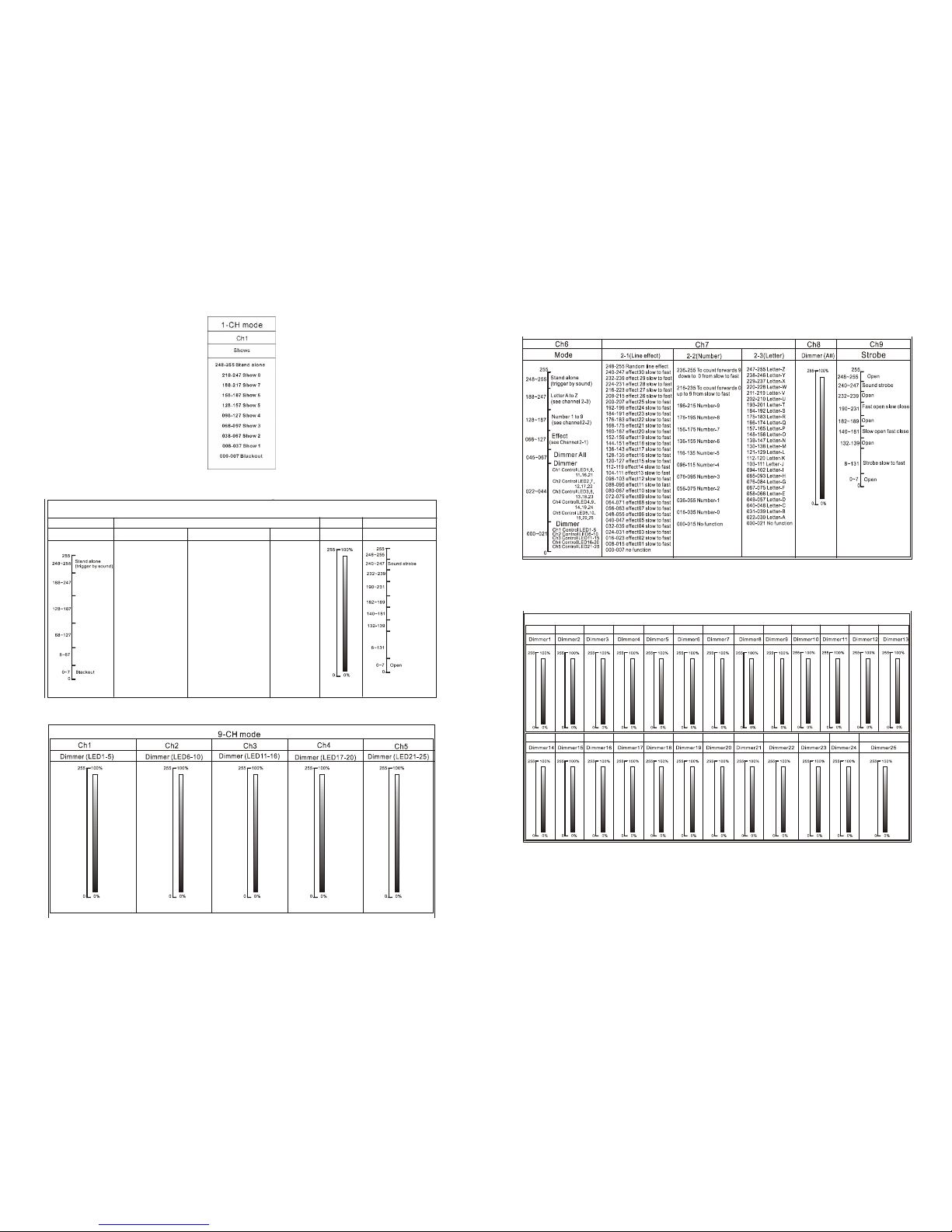
Channel Mode
Press the MENU button up to when the is shown on the display. Pressing the
ENTER button, Use the DOWN and UP button to select the (1 channel) or
(4 channels) or (9 Channels) or (25 channels) or (29
Channels) mode. Once selected, press the ENTER button to setup or automatically exit
menu mode without any change after 60 seconds. To go back to the functions without any
change press the MENU button
Slave Mode
Press the MENU button up to when the is shown on the display. Pressing the
ENTER button, Use the DOWN and UP button to select the (slave 1) or
(Slave 2) mode. Once selected, press the ENTER button to setup or automatically exit menu
mode without any change after 60 seconds. To go back to the functions without any change
press the MENU button.
Set Mode
Press the MENU button up to when the is shown on the display. Pressing the
ENTER button, Use the DOWN and UP button to select the or or
mode. Once selected, press the ENTER button to setup or automatically exit
menu mode without any change after 60 seconds. To go back to the functions without any
change press the MENU button.
Show Mode
Press the MENU button up to when the is shown on the display. Pressing the
9A
ENTER button, Use the DOWN and UP button to select the (Random show) or
(show 1) or (Show 2) or … or (show8). Once selected, press the
ENTER button to store or automatically exit menu mode without any change after 60
seconds. To go back to the functions without any change press the MENU button
Manual Mode
Press the MENU button up to when the is shown on the display. Pressing the
ENTER button, Use the DOWN and UP button to select the (number) or
(letter). Once selected , Pressing the ENTER button, Use the DOWN and
UP button to select the or…or , Once selected, press the ENTER button to
store. If you select , Pressing the ENTER button, Use the DOWN and UP button to
select the or…or , Once selected, press the ENTER button to setup or
automatically exit menu mode without any change after 60 seconds. To go back to the
functions without any change press the MENU button
Sound
Press the MENU button up to when the is shown on the display. Pressing the
ENTER button, Use the DOWN and UP button to select the (sound on) or
(sound off). Once selected, press the ENTER button to setup or automatically exit menu
mode without any change after 60 seconds. To go back to the functions without any change
press the MENU button.
Blackout mode
Press the MENU button up to when the is shown on the display. Pressing the
ENTER button, Use the DOWN and UP button to select the (blackout) or
(normal). Once selected, press the ENTER button to setup or automatically exit menu mode
without any change after 60 seconds. To go back to the functions without any change press
the MENU button.
LED display
Press the MENU button up to when the is shown on the display. Pressing the