ARTHUR HOLM AHDTLM UC User manual

User manual
__________________________________________________
AHDTLM UC
Motorized microphone system for underneath installation

2
Welcome
Thank you for purchasing an ARTHUR HOLM product.
Our product range has been designed to create the perfect
meeting room, where the screens are a part of the interior
design as well as essential communication tools
Please, read this installation and operating instructions
carefully and keep them in a safe place for a future
consultation
We remain at your entire disposal if you have any suggestions
that would help us to improve our products
Henrik Holm
General Manager

3
Table of contents
FEATURES 6
BOX CONTENTS 6
CONTROLS 7
CONNECTIONS 8
AHNET PROTOCOL 10

4
EC NORMATIVE AND SECURITY NORMS
ATTENTION: Do not disassemble or modify the device in any way
This symbol warns of the presence of dangerous un-insulated voltages
inside some of the components, of sufficient magnitude to expose people to
risk of electronic shock
This symbol draws attention to important use and maintenance instructions
in the manual that accompanies the unit
This symbol indicates that the equipment conforms to the norms
established by European community
Safety instructions
Plugs
Do not dismantle any part of the equipment power connector
Disconnect the power plug from the AC outlet when the equipment is not
going to be used for an indefinite period of time

5
Power and extensions cords
Use the appropriate power cord with the correct plug type
Do not overload wall outlets or power cords
Make sure the total ampere passed through an extension cord does not
exceed the maximum allowed by the cable used
Do not place anything on the power cord
Do not locate this product where a person may walk or trip over the cord
Wiring connected to hazardous voltage requires
installation by qualified personnel or the use of ready-
made flexible cables
For your security, your equipment must be
connected to an electrical outlet with
grounding connection protection
The operating electrical outlet must be in an easily accessed place
Environment
Install the equipment on an elevated, flat surface
Install the equipment in a ventilated area
Avoid exposing the equipment to:
-Rain or water
-Excessive heat, cold or humidity
-Areas exposed to direct sunlight
-Dirty areas
-Equipment generating strong magnetic fields
Avoid placing open containers of liquid, near the equipment
Keep a minimum distance of 30mm in order to have good ventilation
Never place any source of flames such as lighted candles, etc above the
device
If you are using the device in extreme weather conditions and / or tropical
climates, the equipment should be installed in a room which ensures a
reasonable level of temperature and humidity
To prevent damage the equipment must be firmly anchored to the surface,
as shown in the installation instructions

6
Features
-Universal microphone lift system
-Two different modes of operation: PA (public address) or conference
(controlled by external conference system control)
-Up, down mechanical function controlled by externally push buttons,
and external control by AHnet protocol (RJ45). The AHnet is an
addressable RS422 protocol to externally control the equipment
-Dynamic LED ring for “ready to talk” and “talk” indications
-Up/Down movement for external push buttons. Down control
movement for cover plate button
-Push button to MUTE function in PA mode, or used to GPO in
conference mode
-In PA mode, the microphone is muted when it is down
Box contents
Before the installation of your DynamicTalk, please check the contents of
the shipping carton, it must contain the following items:
-DynamicTalk
-Power cord
-User’s Manual
-Power supply 100-240Vac, 50-60Hz. Output 12V
CAUTION: Never use this equipment on horizontal
position

7
Controls
On upper cover plate, there are tree push buttons to control the functions
and to external control other devices (GPO).
1. DOWN: Control the down microphone lift movement
2. Customized: The central push button, is used to control external
devices. The contact close button (GPO) is present on SubD9
connector to external control other devices
3. TALK or GPO: The third push button has two different functions
PA mode: Working in PA mode, this button is used as MUTE
function. Press one time the button, the ring LED goes to red
indicating that the mute is not active and you can talk to the
audience. Press once the button, the ring LED change to green
indicating that the MUTE is active and the microphone is not
working
Conference mode: In conference mode, the microphone is
controlled by the external conference system. Then, this button
has no function and the contact close of the push button is present
on the SubD9 control connector (GPO). In this case, there are two
GPO buttons available
-Dynamic ring LED: The system has a ring LED to indicate the status of
the microphone: RED the MUTE is not active, and GREEN the MUTE is
active. When the equipment is configured to work as conference mode
the RING LED is external controlled by GPI on the SubD9 external
control connector

8
Connections
-Microphone out: XLR connector of the microphone installed in the
DynamicTalk
-12V DC IN: XLR4 connector to the power supply
-1,2: Ground
-3,4: 12VDC
-GPI/GPO: SubD 9 pins female connector to contact close external
functions. Connect the external UP/DOWN push button to this
connector
Pin Function
1,6 Contact close of the customised push button
on upper cover plate (central button).
100mA Max.
8,9
Only in conference mode
Contact close of the TALK push button on
upper cover plate, only in conference mode.
This function is not working when the device
is configured in PA mode
100mA Max.
2
Only in conference mode
Activates the ring RED LED in conference
mode, connecting to GPI ground
3
Only in conference mode
Activates the ring GREEN LED in conference
mode, connecting to GPI ground
4 Connect this pin to GPI ground to rise up
the microphone
5 Connect this pin to GPI ground to down the
microphone
7 GPI ground
NOTE: In conference MODE, if the 2 and 3 pin are not connected to
ground, the ring LED is off.

9
-Settings: 6 dip switch to configure the DynamicTalk.
Dip switch Function
1,2,3 ON: DynamicTalk configured as PA mode. The Talk push
button controls the microphone mute function
OFF: DynamicTalk configured as conference mode. The
talk push button has no function but the contact close is
present on GPO connector and the ring LED is externally
controlled
4, 5 Only factory. Leave those dip switches off
6 Termination of the RS422 bus. Configure to ON only in
the last device of the RS422 bus
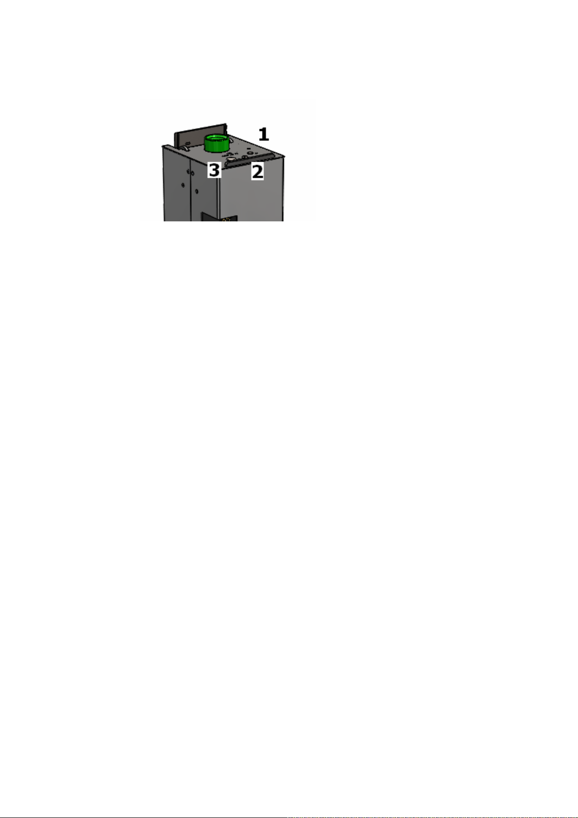
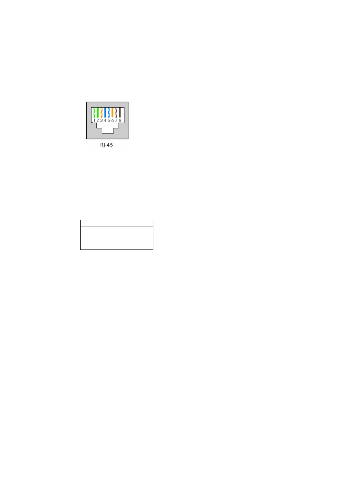
-AHnet: RJ45 CAT5 connector for addressable RS422 control. There is a
loop through connector to use as signal RS422 output. You can
connect up to 30 units on the same RS422 bus
-AHnet ADDRESS: Using the AHnet protocol, this is the number of the
device into the RS422 addressable bus
Microphone length setting procedure.
Dynamic Talk is designed to work with microphones of different lengths.
Two signs to identify an incorrect setup of the microphone length are:
•The microphone do not goes down completely.
•The microphone goes down too low, and gets stucked inside. The
microphone length can be adjusted using Monitor Configurator Tool, but
there is a quick procedure not requiring the PC and the cabling
PROCESS
1. Disconnect Power connector
2. Set switch 5 to ON position
3. Set the length of the microphone in the rotatory
switch, in cm. For instance, if the microphone is
40cm, set the rotatory switch as: tens=4, unit=0)
4. Connect Power , there will be a 5 beep sound
5. Disconnect Power
6. Set switch 5 to OFF position
7. Set the AHnet address in the rotatory switch,
the default setting is address 01 (tens=0, units=1).
8. Connect Power connector

10
AHnet protocol
• Communication type : RS422
• Connection type : RJ45
• Wiring type : CAT-5
• Speed and configuration :
– Baud Rate = 38400
– Data Bits = 8
– Parity = None
– Stop Bits = 1
Wiring diagram
1- Data TX+
2- Data TX-
3- Data RX+
4- NC
5- NC
6- Data RX-
7- NC
8- NC
Pins 1&2: the units answer
Pins 3&6: the units receive orders
Protocol to control the device by addressable RS422 bus. You can connect
up to 30 dvices on the same RS422 bus. You can use a AH Interface
Ethernet, to control the RS422 bus. The units should have set address and
the address must start by 1. Maximum cable length between ends, 500m
AHnet Protocol:
Using 5 bytes to communication:
BYTE 0 START BYTE
BYTE 1 ADDRESS BYTE
BYTE 2 COMMAND BYTE
BYTE 3 VALUE 1
BYTE 4 VALUE2

11
Commands:
COMMAND DESCRIPTION RESPONSE
FA XX 01 01 00 GO UP FB XX 01 01 00
FA XX 01 00 00 GO DOWN FB XX 01 00 00
FA XX 02 01 00 MUTE ON (Only in PA mode) FB XX 02 01 00
FA XX 02 00 00 MUTE OFF (Only in PA mode) FB XX 02 00 00
FA XX 04 01 00 BUTTON LOCK FB XX 04 01 00
FA XX 04 00 00 BUTTON UN LOCK FB XX 04 00 00
FA XX 14 00 00 INQUIRY CONTROL BYTE FB XX 14 CB1 CB2
XX: Number of the DynamicTalk address. Up to 30 units for each RS422
BUS.
CB1: Response in 8 bites of the device status
CB2: Not implemented
CB1:
BIT 0 TOP POSITION
BIT 1 DOWN POSITION
BIT 2 (1) MUTE ON
BIT 3 (1) BUTTON LOCK
BIT 4
BIT 5
BIT 6
BIT 7 (1) FAILURE IN THE SYSTEM
To send an order to all the devices, you must use the address:
F7 Hex. (Byte1)
In this case, the units do not respond

12

13
Information on Disposal for Users of Waste Electrical & Electronic
Equipment
This symbol on the products and/or accompanying
documents means that used electrical and electronic
products should not be mixed with general
household waste
For proper treatment, recovery and recycling,
please take these products to designated collection
points, where they will be accepted on a free of
charge basis. Alternatively, in some countries you
may be able to return your products to your local
retailer upon the purchase of an equivalent new
product
Disposing of this product correctly will help to save valuable resources and
prevent any potential negative effects on human health and the
environment which could otherwise arise from inappropriate waste
handling. Please contact your local authority for further details of your
nearest designated collection point
Penalties may be applicable for incorrect disposal of this waste, in
accordance with national legislation
For business users in the European Union
If you wish to discard electrical and electronic equipment, please contact
your dealer or supplier for further information
Information on Disposal in other Countries outside the European
Union
This symbol is only valid in the European Union
If you wish to discard this product, please contact your local authorities or
dealer and ask for the correct method of disposal

14
PRODUCT GUARANTEE
Conditions of Guarantee
Albiral Display Solutions S.L., with this document, guarantees all Albiral
and Arthur Holm Trademark products against defects in manufacturing in
accordance with the following conditions:
1) This guarantee covers the original product purchaser for a period of 24 months
from the date of purchase
2) This guarantee covers:
a) Parts: During the warranty period, the replacement of any electronic and
mechanical parts against any defects in manufacturing. The guarantee does
not cover any faulty electronic and/or mechanical components arising from
incorrect installation, non-authorised modification, and inadequate transport
or as a result of atmospheric phenomenon
b) Labour: Albiral Display Solutions S.L covers labour costs for replacement of
any defective parts (in accordance to paragraph 2a) during the period of
this warranty
c) Transport costs:
i) In the case that a manufacturing defect occurs within 30 days after the
purchase date, both freight and insurance will be paid by Albiral
Display Solutions, S.L.
Although Albiral Display Solutions S.L pays for transport and
insurance cost, Albiral Display Solutions, S.L. will not be responsible
for the damages caused by transport if the customer does not
inform in writing when receiving the goods
ii) After 30 days of the purchase date, both freight and insurance costs
will be paid by the customer
d) Albiral Display Solutions S.L. will not be responsible for the damages caused
by transport, when this is paid by customer
e) The guarantee is not valid if persons other than authorised service Centre
have handled the product and if the product has been manipulated
f) The beneficiary of the Guarantee will have to send the devices with the
original packaging or an appropriate one to guarantee there are no
damages during the transport
g) The guarantee is not valid if the customer does not include RMA form and
copy of the purchasing invoice
3) Albiral Display Solutions S.L. recognized all guaranteed user rights by all legal
rules from its region, and in the absence of them, all established consumer rights
by general law 26/84
CONTACT YOUR AUTHORISED DISTRIBUTOR

15

16
ARTHUR HOLM
Albiral Display Solutions SL
Fàtima, 25
Sant Hipòlit de Voltregà
08512 Barcelona – Spain
tel: +34 93 850 23 76 / 23 83
fax: +34 93 850 25 50
web: www.arthurholm.com
e-mail:[email protected]
This manual can be modified without previous
notice.
Arthur Holm is a registered brand by Albiral
Display Solutions SL.
Table of contents
Other ARTHUR HOLM Microphone manuals