MIC&MOD U47 User manual
Microphone build guide (U47, 2019 version)
This guide will explain how to build an excellent multipattern tube microphone.
All components are of the highest quality: Styroflex and Wima capacitors, 1% metal
film resistors, a special quality EF806S tube, selected for noise and most important of
all, a high quality microphone capsule.
But first a word of warning:
Do not touch anything inside the microphone when the power supply is
connected. The microphone works with high voltages, that in some situations
can be lethal. When you work on the microphone, ALWAYS disconnect the
power supply. Even when the power supply is switched off, the capacitors
inside the power supply will keep a high voltage for a long time.
As long as you keep this in mind, there isn’t very much that can go wrong.
It might be a good idea to read through this information before you effectively start
assembling the microphone, so you will have an idea about the steps that will follow.
The microphone electronics are build on 2 printed circuit boards (PCB’s).
We will assemble the separate boards one by one and build them later together.
We will start with the small rounded printed circuit board.
First place and solder the tube socket to the PCB.
Take care that one pin goes through the bigger hole, without touching the printed
circuit board.
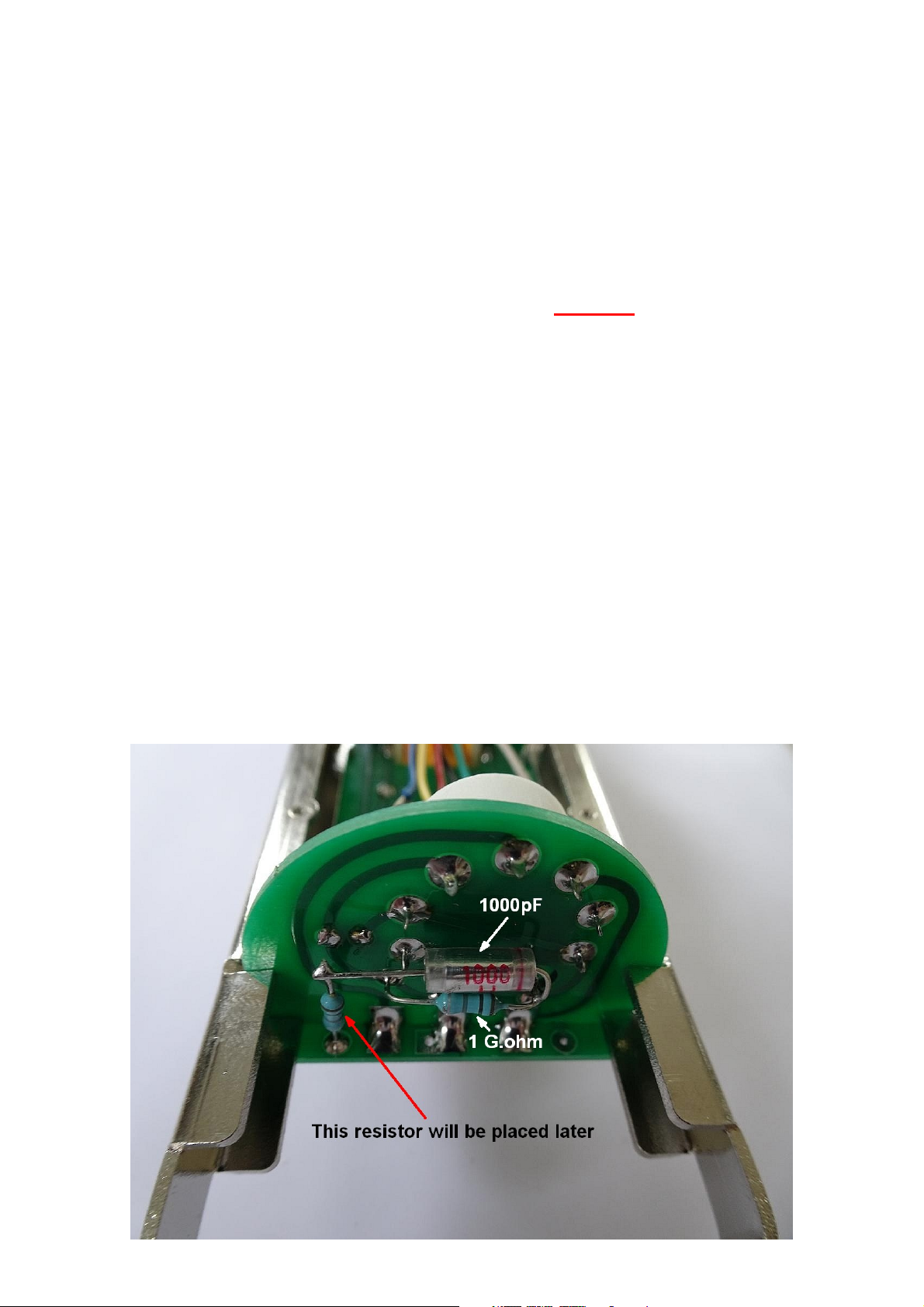
Next, solder a 1 G.ohm resistor (brown/black/grey) on the solder side between the
PCB and the pin in the bigger hole. Keep some distance between resistor and PCB.
Now solder the 1000pF Styroflex capacitor to the junction of the 1 G.ohm resistor and
the pin of the tube socket. We leave the other free end ‘floating’ in the air for the
moment. This is how if should look when the small PCB is later mounted in the
microphone body. (The other resistor you see on the picture, will be added later.)

Now mount the 1 K.ohm resistor (brown/black/black/brown) on the component side
of the small PCB.
Also mount and solder the 47µF capacitor on the component side. (The side where
the tube socket already is.) Take care that the capacitor is mounted with the correct
orientation, the “-“ side should be connected to the trace marked “Gnd.”
When this is done, you can put the small PCB aside for the moment.
Next we assemble the bigger audio PCB.
First we mount and solder 6 resistors, values are clearly marked on the silkscreen:
1 x 10 K.ohm (brown/black/black/red)
1 x 100 K.ohm (brown/black/black/orange)
2 x 2.2 M.ohm (red/red/black/yellow)
2 x 100 M.ohm (brown/black/black/blue)
And the capacitors, the red 2 x 10nF/630V and the two big yellow 1 µF capacitors:
The only part missing on the PCB now is the output transformer.
First we stretch the piece of 1 mm. thick wire and cut it in two pieces.
From the pieces of wire, we bend two “U” formed shapes, with 30 mm. between both
legs of the “U”. We will use these wires to secure the transformer to the PCB.
Place the BV8 transformer in the rectangular cutout of the PCB. Wires up.
Don’t force anything!
When the transformer is flat on the PCB, place the “U” formed wires over the core of
the transformer (on both sides) and lead the ends through the holes in the PCB.
Make sure the wires rest on the core of the PCB, so that the transformer can not
move. Now cut the excess length of the 1 mm. wires on the solder side of the PCB
and solder the ends. Now the transformer is fixed in place on the PCB.
Cut the transformer wires to length, strip and tin them and solder the wires to the
points indicated on the picture:
Now mount the PCB in the microphone body with four M2x5 screws, at the side
where a screw of the XLR connector is visible.
Now comes the tricky part...
Remove the headbasket. Place the small PCB in the slots in the rails, in such a way
that the tube socket points into the direction of the XLR connector in the bottom.
If everything is well, you can push the small PCB completely down to the audio
PCB. If you can not do this, because the small PCB touches solder joints, mark these
points and use a small round file to remove some PCB material at these places.
Be careful not to destroy traces on the small tube PCB!
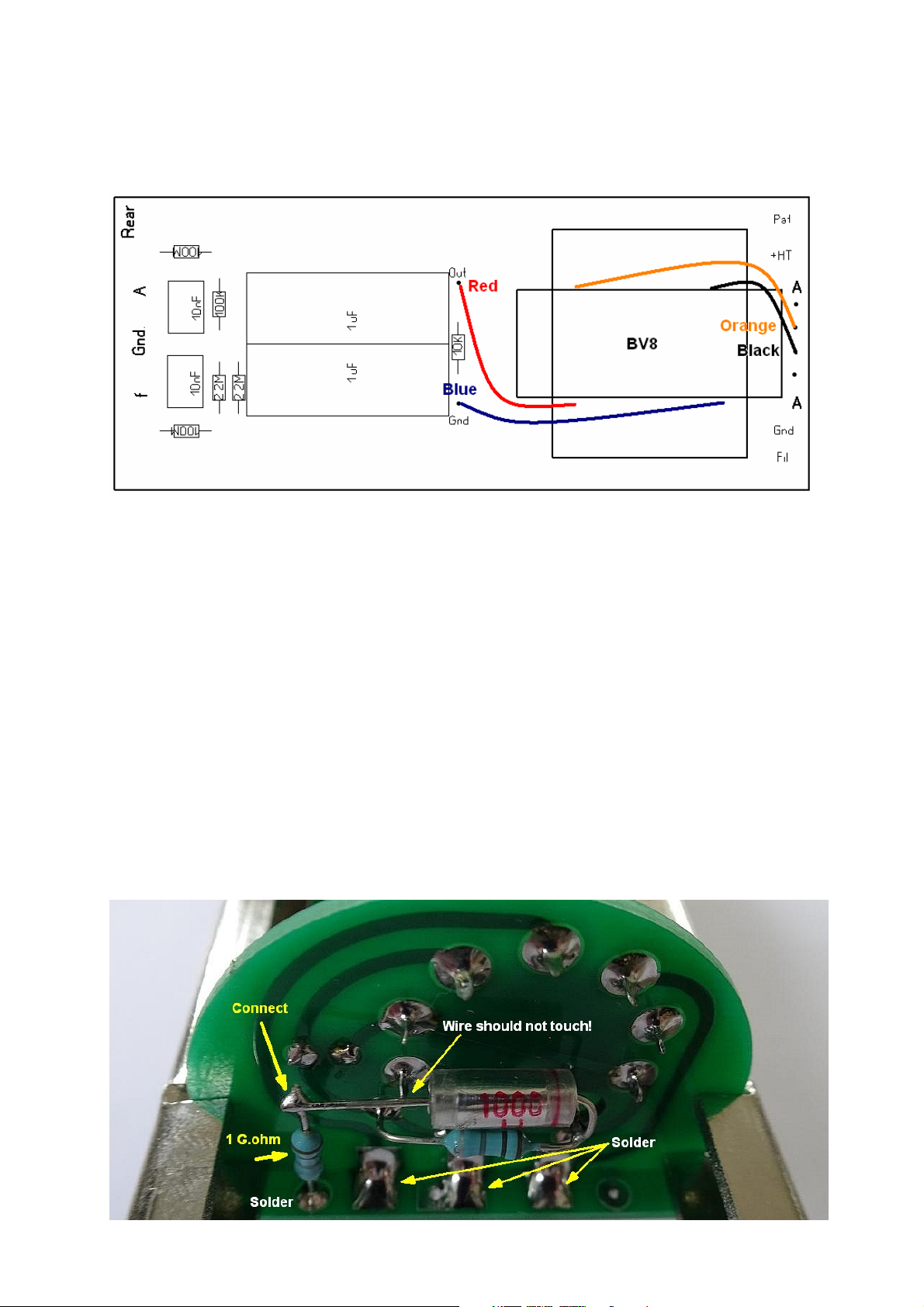
Now, there are 3 points where the two PCBs should be joined. Use three little ‘blobs’
of solder to connect the two PCBs.
You can eventually temporarily remove the round plate where the capsule mount is
placed on; this will give you better access to the places to be soldered.
If this is done, connect a 1 G.ohm resistor between the spot on the left side of the
main PCB and the open end of the 1000pF Styroflex capacitor, we have soldered to
one pin of the tube socket before. If everything is as it should, it should look like this:

Next, mount the microphone capsule to the saddle with the supplied screws and
washers. DO NOT TOUCH THE MEMBRANES!
Lead the wires of the capsule through the holes in the bottom plate of the headbasket
compartment. It may be a good idea to mark which wire is coming from the front
membrane, and which one is coming from the rear membrane. The backplate wire
(connected to the side of the capsule) usually has a differen color, so the function of
this wire is clear.
In some cases, the backplate wire is connected tot a point you need to screw the capsule to the
mount. In that case, carefully remove the screw with the backplate wire and move it to a position
where it is not in the way of the mounting holes in the saddle.
Now comes a part that requires some ‘micro surgery skills’...
(During this procedure you may want to leave the headbasket off for better access,
but if you do so, cover the capsule with a plastic bag, to prevent flux ‘splashing’ on
the membranes while soldering.)
- Solder the backplate wire to the point where the 1 G.ohm resistor and the 1000pF
capacitor are connected and are ‘floating in the air’.
- Solder the wire from the front membrane to the point on the audio PCB marked
“Gnd.”
- Solder the wire from the rear membrane to the point on the audio PCB marked
“Rear”.
If this is done, secure the headbasket with two screws.
Now solder the wires coming from the XLR connector to the audio PCB:
Fil: Yellow wire, filament voltage
Gnd: White wire, Ground
A: Black wire, Audio (black from transformer)
A: Green wire, Audio (orange from transformer)
+HT: Red wire, +120V
Pat: Blue wire, pattern selection
The last thing to do, is to insert the EF808S tube.
This goes easier, if you first push the end of a paperclip in all contacts of the tube
socket. Doing so, will make them a little bit wider, so it is easier to put the tube in.
In principle the microphone is finished now!
XLR wire connections

If you make the microphone cable yourself:
You connect all pins in the XLR Male and female connector 1:1, so: pin 1 of the male
XLR to pin 1 of the female XLR etc.
Pin 4 and 7 (center) are connected together and are also connected to the shield
(screening) of the cable.
It doesn’t really matter which colors you connect to which pin, as long as the pin
numbers on both sides match.
But... if your cable has two conductors that are thicker than the other wires, use
these thicker wires for pin 2 (filament) and pins 4/7 (ground).
Take care not to accidentally connect two pins together. Don’t use too much solder!
Schematic:
Version 1.0 / 12-07-2019 / RvS.
Table of contents
Other MIC&MOD Microphone manuals

Popular Microphone manuals by other brands


Avermedia
Avermedia LIVE STREAMER MIC 350 quick start guide

Crown
Crown PZM-11LLWR datasheet

Omnitronic
Omnitronic HS-500 user manual

LY International Electronics
LY International Electronics CM12 Operation instructions

Electro-Voice
Electro-Voice RE410 Specification sheet

Beyerdynamic
Beyerdynamic MCW-D 521 manual


