Artila M-508 User manual

Overview
M-508 is a Linux ready Single Board Computer featuring four
serial ports, 10/100 Mbps Ethernet, USB port and SD socket for
flash disk expansion. The pre-install Linux OS and GNU tool
chain make M-508 ready for your application development.
Features
1. ARM920T ARM Thumb Processor with 200MIPS at
180MHz, Memory Management Unit
2. 16-KByte Data Cache and 16-KByte Instruction Cache
3. 64MB SDRAM, 32MB Flash on board
4. 512KB non-volatile FRAM (M-508T only)
5. One 10/100 Mbps Ethernet
6. Two USB 2.0 full speed (12 Mbps) Host Ports
7. Multimedia Card Interface for SD memory card
8. Four RS-232/485 ports software selectable
9. Port 4 also supports RS-422
10. 32 General Purpose DIO
11. +5VDC power input
12. Pre-installed Standard Linux 2.6.14 OS
13. GNU tool chain available in Artila CD
Packing List
M-508 is shipped with following items
1. M-508
2. CB-F10M9-20 10-pin header to DB9 male cable x4
3. Artila CD includes Tool Chain, Installation guide and
example programs
Optional Accessory
1. CB-F9F9-150: DB9 Female serial console Cable
M-508 Layout
M-508 Quick Installation Guide
3.0 mm
3.0 mm
Screw: Φ 3 mm
JTAG CN1
Power LED
Ready LED
LAN LED

Power LED (PWR)
Power LED will keep solid green when power is applied.
Ready LED (RDY)
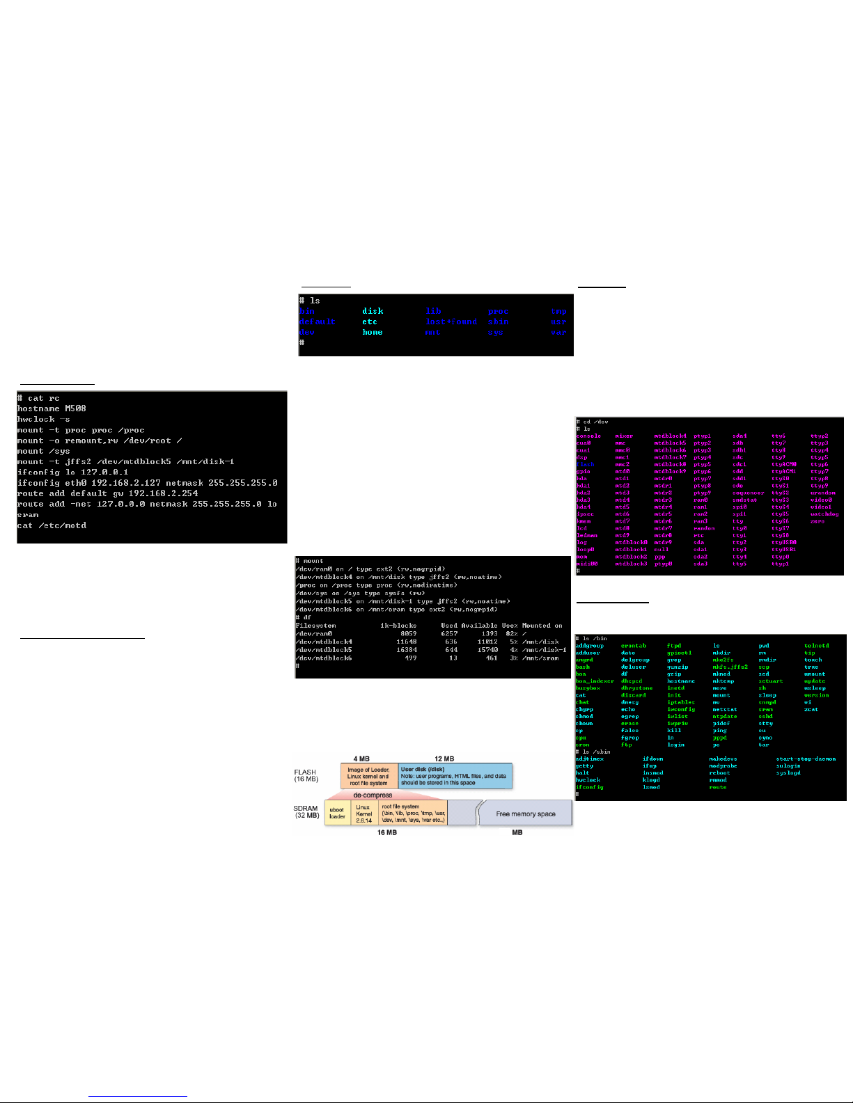
After Power ON, M-508 will decompress the kernel and root file
system to RAMDISK. Once system is boot up, the Ready LED will
show solid green. The Ready LED will be turned off after M-508
received “halt” command.
Link/Act (LAN)
When Ethernet port are connected to the network, Link/Act will show
solid green and if there is traffic in the Ethernet, this LED will flash
Serial Port LED (LD3~LD6)
These four dual color LEDs indicate the data traffic at the serial ports.
When RXD line is high then Orange light is ON and when TXD line
is high, Green light is ON.
Debug LED (LD1~2)
The debug LEDs are located near LAN LED and are used for system
boot debug. If system are correctly boot, they are switch off.
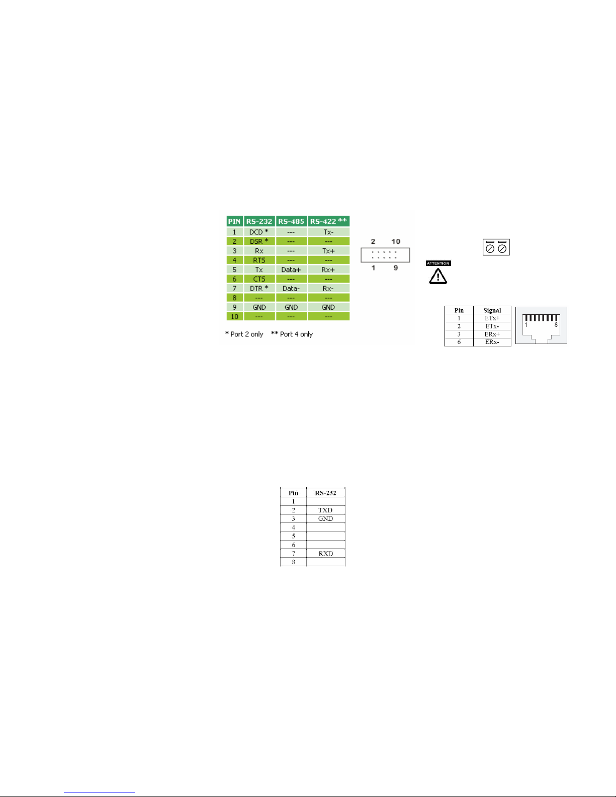
Serial Port
The serial port pin assignment is shown as follow:
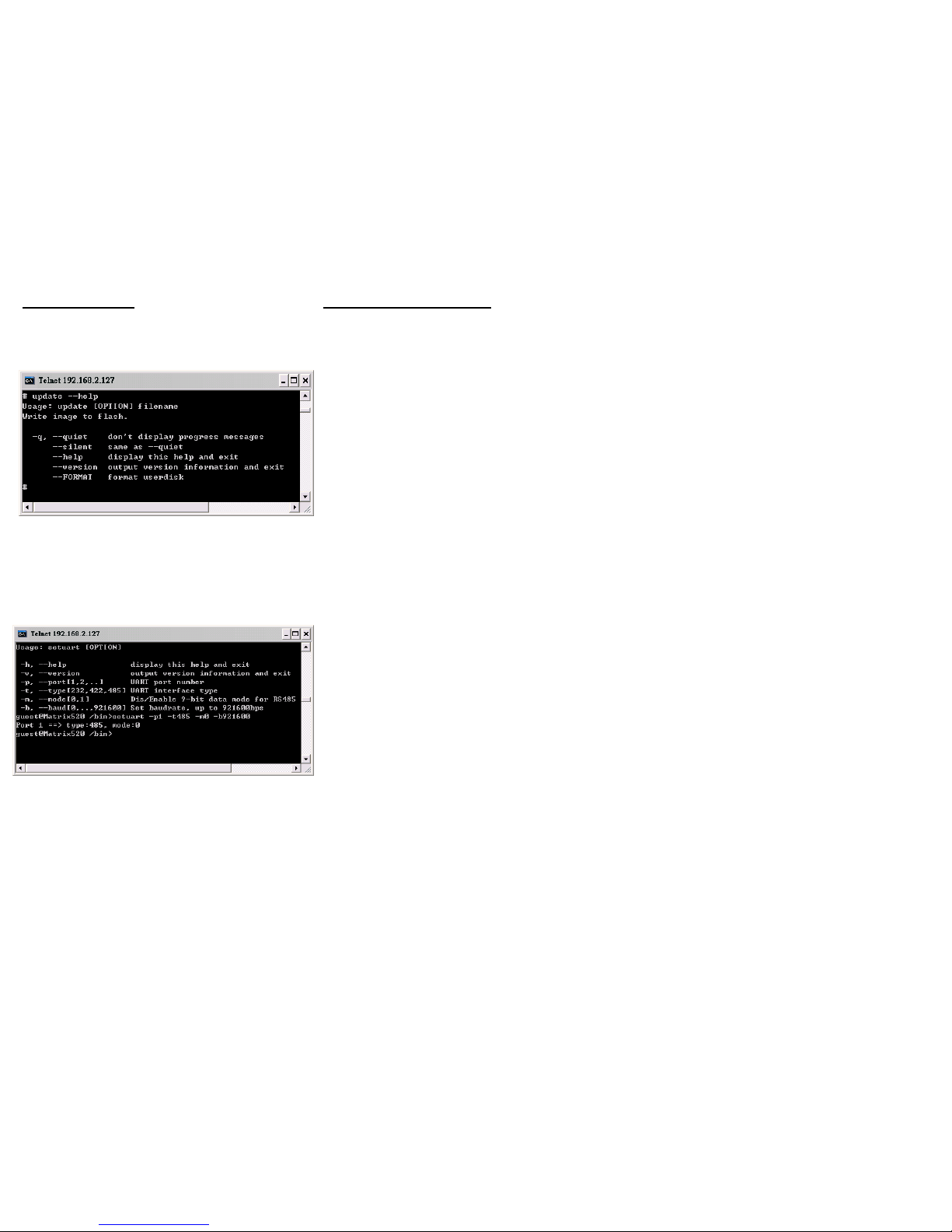
Port 1/3: RS-232/422 (software selection)
RS-232: RXD,TXD,RTS,CTS,GND
RS-422: TXD+, TXD-,RXD+,RXD-,GND
Port 2: RS-232/422 (software selection)
RS-232: RXD,TXD,RTS,CTS,DSR,DTR,DCD,GND
RS-422: TXD+, TXD-,RXD+,RXD-,GND
Port 4: RS-232/422/485 (software selection)
RS-232: RXD,TXD,RTS,CTS,GND
RS-422: TXD+, TXD-,RXD+,RXD-,GND
RS-485: Data+, Data-, GND
Serial Console Port:
Serial console port is used for accessing M-508 using RS-232. At
factory, serial console port is disabled because serial console port
shares the Port 3 connector with the pin definition as shown:
User need to prepare or order a serial console cable
(CB-F9F9-100) and enable the serial console port as described in
Enable Serial Console port section.
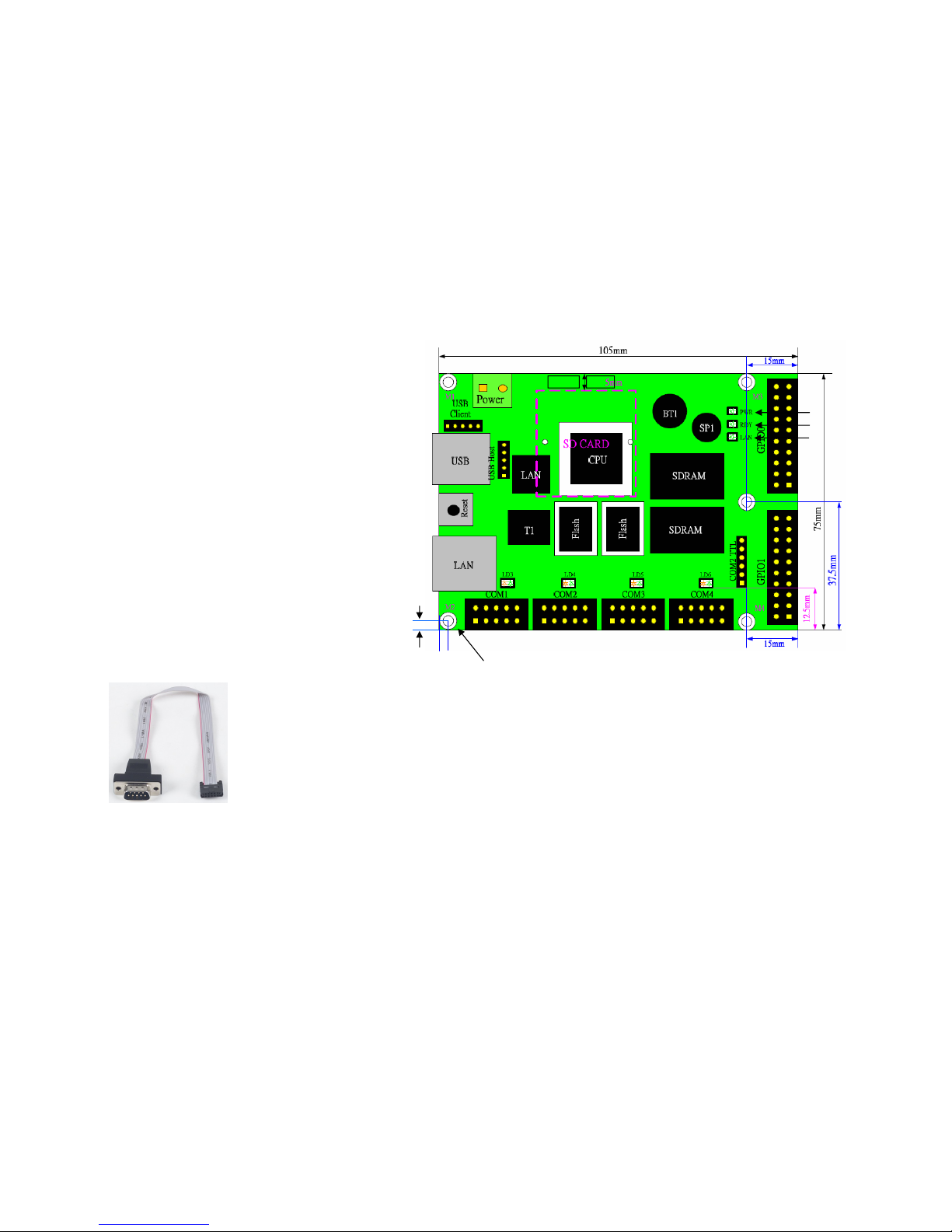
Power Connector
Connect the +5VDC power line to M-508. If the power is
properly supply, the power LED will show a solid green color.
Please check the power voltage
and polarity before connecting it
Ethernet Port
The Ethernet Port uses RJ45 connector
SD Socket
The SD socket is compatible with SD memory card
specification version 1.0. The SD Socket is located in the back
panel of the PCB.
USB Port
The USB port is a USB2.0 high speed host port. It can be used
to expand the hardware function of M-508 and exchange file
and data between PC. Currently the hardware support by M-
508 USB is shown as follow:
1. USB Storage Device
2. USB to Wireless LAN Adaptor (Ralink RT2571)
3. USB to Modem (CDC compliant)
4. USB Camera
Contact Artila if you find your hardware is not shown on the
list.
Reset Button
Press the “Reset” button to activate the hardware reset. Please
always use “reboot” command to reset M-508. You should
only use this function if the software reboot does not function
properly.
+
-

General Purpose IO (GPIO)
GPIO signals are housed in a 20-pin box connector, GPIO1 and
GPIO2. Each of the connector includes 16 channels of GPIO. The
pin definition is as shown following:
The signal level of GPIO is CMOS level and pitch of the pin header
is 2.54 mm. Each of the DIO pin can be programmed as digital input
or digital output.
CN1 JTAG Header
JTAG header is located near power connector and it is a 2x4 2.0 mm
pin header and the pin definition is shown as follow:
COM2 TTL Header
COM2 TTL is a CMOS/TTL signal pin connector and it is
connected to UART of port 2 and its definition is as shown
below
This connector allows user to design an internal Modem to work
with M-508.
JP2 Boot manager selection
JP2 is boot selection jumper near CN1. Set to position 2-3
always. Change the setting will cause incorrectly boot up.
USB Client connector (J3)
USB client port is reserved for future enhancement. This
function is disabled by software.
Pin definition is as follow:
1. Data +
2. Data -
3. Host_detect
4. GND
RS-485 terminator jumper (J5,J7,J8,J9)
Short the jumper will enable the 120 ohm terminator as shown
below
1
2
34
5
6
78
910
1112
1314
1516
1718
1920
DI0
DI2
DI4
DI6
DI8
DI10
DI12
DI14
GND
+5V
DI1
DI3
DI5
DI7
DI9
DI11
DI13
DI15
GND
+3.3V
1
2
34
5
6
78
910
1112
1314
1516
1718
1920
DI16
DI18
DI20
DI22
DI24
DI26
DI28
DI30
GND
+5V
DI17
DI19
DI21
DI23
DI25
DI27
DI29
DI31
GND
+3.3V
GPIO1 GPIO2
2 4 6 8
1 3 5 7
JTAG
Definition
6
5
4
3
2
1
GND
+5VDC
RTS
TXD
CTS
RXD
3 2 1
1 2 3 4

Factory Default Settings
LAN 1 IP Address: 192.168.2.127
Login: guest
Password: guest
Supervisor: root (use ssh to login)
Password: root
Serial Console: Disabled
Network Settings
To configure the IP address, Netmask and Gateway setting, please
modify /disk/etc/rc as following:
ifconfig eth0 192.168.2.127 netmask 255.255.255.0
For DHCP setting:
dhcpcd eth1 &
Wireless LAN Configuration
M-508 supports wireless LAN by using USB WLAN adaptor
which uses Ralink RT2571 (rt73) controller. Please refer to the
website http://ralink.rapla.net for the supporting list of the USB
WLAN adaptor.
To configure the wireless LAN setting, please use command:
modprobe rt73
ifconfig wlan0 up
iwconfig wlan0 essid XXXX key YYYYYYYY mode MMMM
For infrastructure mode XXXX is the access point name and
YYYYYYYY is the encryption key and MMMM should be
managed
For Ad-Hoc mode mode XXXX is the M-508 host name and
YYYYYYYY is the encryption key MMMM should be ad-hoc.
To configure the IP address use command
dhcpcd wlan0 & or ifconfig wlan0 192.168.2.127 netmask
255.255.255.0
File System
M-508 configures the root file system as RAMDISK and the user
disk (/disk) which includes /home and /etc directory are
configured as Flash Disk. To find out the file system information,
please use command /mount as shown as below. In addition, use
command /df to find out the disk space of the disk. The
RAMDISK uses 8MB SDRAM space to store the root file system
and 8MB for uboot loader and Linux Kernel Therefore it is about
16MB free SDRAM for user application software. The image of
Linux kernel and root file system is stored in the flash memory
and it uses about 4MB flash memory space and the rest of 12MB
flash memory is designed for user flash disk to store user’s
program.
Therefore, user’s program and utility software must be saved
in the user disk space (/disk). Files saved to other directory
Utility Software:
M-508 includes busybox utility collection and Artila utility
software as follow:
Devices list
The supported devices are shown at /dev directory. Following
list are most popular ones:
1. ttyS0: serial console port
2. ttyS1 to ttyS4: serial port 1 to port 4
3. mmc to mmc2: SD memory card
4. sda to sde: USB flash disk
5. ttyUSB0 to ttyUSB1: USB RS-232 adaptor (fdti_sio.ko)
6. rtc: Real Time Clock
7. gpio: General Purpose digital I/O
8. ttyACM0 and ttyACM1: USB Modem (CDC compliant)
48
The second flash memory is configured as disk-1 and its
available space is 15MB. In addition, M-508T is equipped with
512KB FRAM and it is configured as sram

Artila Utility Software:
The introduction of Artila utility software as follow:
1. update : update loader, kernel or root file system image.
Also use update —FORMAT to format user disk. Type
update—help to find the command usage
Update can only operated under supervisor mode (password :
root)
2. setuart: configure serial port setting. An example show as
followed to configure port 1 as RS-485 interface with baud rate
921600. Please note only port 1 support 9-bit data at RS-485
How to make more utility software
You might also find utility software available on Artila CD
under /Matrix and iPAC/utility such as ntpclient, ssh, scp, bluez
and ssh-keygen. If you want, you can ftp or copy the utility
software to M-508 user disk (/disk). Also you can use find the
source code and use the GNU Tool Chain to make the utility by
yourself.
Table of contents
Other Artila Motherboard manuals