ArWest alphawave AW100 User manual

AlphaWave Users Manual
AlphaWave Users Manual 4/26/2006


COPYRIGHT NOTICE
Copyright 2004 ArWest Communications Corp. All rights reserved.
No part of this publication or the computer programs described
herein may be reproduced, translated, stored in a retrieval system,
or transmitted in any form or by any means, electronic, mechanical
photocopying, recording or otherwise, without prior written permis-
sion of ArWest Communications Corp. Your rights with regard to this
publication and the computer programs are subject to the restric-
tions and limitations imposed by the copyright laws of the United
States of America (“U.S.A.”) and/or the jurisdiction in which you are
located. For information on translations and distribution outside the
U.S.A., please contact ArWest Communications.
Printed in the United States of America
Part Number: UF-00001-100
March 05
TRADEMARK NOTICE
ArWest is the registered trademark of ArWest Communications Corp.
AlphaWave, AW and AWare are trademarks of ArWest Communica-
tions Corp. All other product and brand names are trademarks or
registered trademarks of their respective holders.
SOFTWARE LICENSING AGREEMENT
IMPORTANT: BY OPENING THE SEALED DISK PACKAGE CONTAINING THE SOFT-
WARE MEDIA OR INSTALLING THE SOFTWARE YOU ARE AGREEING TO BE BOUND
BY THE TERMS AND CONDITIONS OF THE LICENSE AGREEMENT (‘AGREEMENT’).
THIS AGREEMENT CONSTITUTES THE COMPLETE AGREEMENT BETWEEN YOU
(‘LICENSEE’) AND ARWEST (‘LICENSOR’). CAREFULLY READ THE AGREEMENT
AND IF YOU DO NOT AGREE WITH THE TERMS RETURN THIS UBPOPENED DISK
PACKAGE AND THE ACCOMPANYING ITEMS TO THE PLACE WHERE YOU OBTAINED
THEM.
LICENSE: LICENSOR grants you a limited, non-exclusive, non-
transferable, personal license (‘License’) to (i) install and operate the
copy of the computer program contained in this package (‘Program’)
in machine acceptable form only on a single computer (one central
processing unit and associated monitor and keyboard) and (ii) make
Page—iii

one archival copy of the Program for use with the same computer.
LICENSOR and its third-party suppliers retain all rights to Program
not expressly granted in this Agreement.
OWNERSHIP OF PROGRAMS AND COPIES. This License is not a sale
of the original Program or any copies. LICENSOR and its third-party
suppliers retain the ownership of the Program and all copyrights and
other propriety rights therein, and all subsequent copies of the Pro-
gram made by you, regardless of the form in which the copies may
exist... The Program and the accompanying manuals
(‘Documentation’) are copyrighted works of authorship and contain
valuable trade secret and confidential information propriety to LI-
CENSOR and its third-party suppliers. You agree to exercise reason-
able efforts to protect the proprietary interests of the LICENSOR and
its third-party suppliers in the Program and Documentation and
maintain them in strict confidence.
USER-RESTRICTIONS. The Program is provided for use in your in-
ternal commercial business operations and must remain at all times
upon a single computer owned or leased by you. You may physically
transfer the program from one computer to another provided that
the Program is operated only on one computer at a time. You may
not operate the Program in a time-sharing or service bureau opera-
tion or rent, lease, sublease, sell, assign, pledge, transfer, transmit
electronically or otherwise dispose of the Program or Documentation,
on a temporary or permanent basis, without prior written consent of
LICENSOR. You agree not to translate, modify, adapt, disassemble,
decompile, or reverse engineer the program, or create derivative
works of the Program or Documentation or any portion thereof.
TERMINATION. The License is effective until terminated. The Li-
cense will terminate without notice from LICENSOR if you fail to
comply with any of the provisions of this Agreement. Upon termina-
tion, you must cease all use of the Program and Documentation and
return them and any copies thereof to LICENSOR.
GENERAL. This Agreement shall be governed by and construed in
accordance with the Laws of the State of California and the United
States of America without regard to conflict of laws provisions
thereof and without regard to the United Nations Convention on Con-
tracts for the International Sale of Goods.
Page—iv
AlphaWave Users Manual 4/26/2006

DISCLAIMER OF WARRANTIES AND LIMITATIONS OF LIABILITY
LICENSOR AND ITS THIRD-PARTY SUPPLIERS MAKE NO WARRANTIES OR REPRE-
SANTATIONS, EXPRESS OR IMPLIED, REGARDING THE PROGRAM, MEDIA, DOCU-
MENTATION, RESULTS OR ACCURACY OF DATA AND HEREBY EXPRESSLY DISCLAIM
ANY WARRANTIES OF MERCHANTABILITY AND FITNESS FOR PARTICULAR PURPOSE
AND NONFRINGEMENT. LECENSOR AND ITS THIRD-PARTY SUPPLIERS DO NOT
WARRANT THE PROGRAM WILLMEET YOUR REQUIREMENTS OR THAT IT’S OPERA-
TION WILL BE UNINTERRUPTED OR ERROR-FREE.
LICENSOR, its third-party suppliers, or anyone involved in the crea-
tion or delivery of the Program or Documentation to you shall have
no liability to you or any third-party for special, incidental, indirect or
consequential damages (including, but not limited to, loss of profits
or savings, downtime, damage to or replacement of equipment or
property, or recover or replacement of programs or data) arising
from claims based in warranty, contract, tort (including negligence),
strict liability, or otherwise even if LICENSOR or its third-party sup-
pliers have been advised of the possibility of such claim or damages.
The liability of the LICENSOR and its third-party suppliers for direct
damages shall not exceed the actual amount paid for this Program
License.
Some states do not allow the exclusion of limitation of implied war-
ranties or liability for incidental or consequential damages, so the
above limitations may not apply to you.
U.S. GOVERNMENT RESTRICTED RIGHTS
The Program and Documentation are provided with RESTRICTIVE
RIGHTS. Use, duplication, or disclosure by the Government is sub-
ject to restrictions as set forth in subdivision ©(1)(ii) of the Rights in
Technical Data and Computer Software clause at DFARS 252.227-
7013 or subdivision 9©(1) and (2) of the Commercial Computer
Software – Restricted Rights 48 CFR 52.227.19 as applicable.
Should you have any questions concerning the Limited warranties
and Limitation of Liability, please contact in writing: ArWest Commu-
nications Corp. 300 Orchard City Drive, Suite#126, Campbell, CA
95008, USA
Page—v
AlphaWave Users Manual 4/26/2006

EMISSIONS
FCC FCC Part 90
ETSI 300-113
Industry Canada RSS-119
NOTICE
Changes or modifications not expressly approved by ArWest Com-
munications Corporation could void the user’s authority to operate
this equipment.
Shielded cable must be used with this equipment in order to ensure
that it meets the emissions limits for which it was designed. It is
the responsibility of the user to obtain and use good quality shielded
cables with this device. Shielded cables are available from most re-
tail and commercial suppliers of cables designed to work with radio
equipment and personal computer peripherals.
406.0 TO 406.1 MHZOPERATION
The frequency band from 406.0 to 406.1 MHz is reserved for use by
distress beacons. As such AW400 should not be programmed to
transmit on any frequency within this band. Caution should be used
when programming frequencies into the AW400 to eliminate the pos-
sibility of AW400 users interfering with rescue operations in this
band (US only).
SAFETY WARNING
In order to ensure the safe operation of this radio equipment, the
following practices should be observed.
DO NOT operate radio equipment near electrical blasting caps or in an
explosive atmosphere
DO NOT operate any radio transmitter unless all RF connectors are
secure and any open connectors are properly terminated.
DO NOT allow the antenna to come close to, or touch, the eyes, face,
or any exposed body parts while the radio is transmitting.
Page—vi
AlphaWave Users Manual 4/26/2006

AlphaWave Users Manual 26/4/2006
Index-1
TABLE OF CONTENTS
COPYRIGHT NOTICE iii
TRADEMARK NOTICE iii
SOFTWARE LICENSING AGREEMENT iii
DISCLAIMER OF WARRANTIES AND LIMITATIONS OF LIABILITY v
U.S. GOVERNMENT RESTRICTED RIGHTS v
EMISSIONS vi
NOTICE vi
406.0 TO 406.1 MHZOPERATION vi
SAFETY WARNING vi
1. INTRODUCTION 1-1
1.1 WHAT IS THE ALPHAWAVE (AW) SYSTEM 1-1
1.1.1 MODEL NUMBERS 1-2
1.1.2 NETWORK TOPOLOGIES 1-2
1.1.3 OPERATING MODES 1-4
1.1.4 MANAGEMENT TOOLS 1–4
1.2 ITEMS SUPPLIED WITH AW 1-5
1.2.1 AW TRANSCEIVER 1-7
1.2.2 AW INTERFACE CABLE 1-7
1.2.3 DATA CABLE 1-7
1.2.4 ALARM/SENSE INTERFACE 1-8
1.2.5 SERIAL MAINTENANCE INTERFACE 1-8
1.2.6 LINK ALARM/STATUS INDICATORS 1-8
1.2.7 POWER INTERFACE 1-9
1.2.8 RF INTERFACE 1-9
1.2.9 ANTENNAS 1-9
1.2.10 MAXIMUM PERMISSIBLE EXPOSURE LEVELS 1-10

AlphaWave Users Manual 26/4/2006
Index-2
2. CONFIGURE YOUR ALPHA-WAVE 2-1
2.1 PLUG AND PLAY (DEFAULT SETTING) 2-1
2.2 BASE SETUP 2-1
2.3 REMOTE SETUP 2-1
2.4 REPEATER SETUP 2-1
2.5 INSTALL NEW FIRMWARE 2-2
3. AWARE - GENERAL DESCRIPTION 3-1
3.1 PRODUCT FEATURES 3-2
3.1.1 MANAGEMENT 3-2
3.1.2. ALARMS 3-2
3.1.3 STATISTICS 3-2
3.2 PRODUCT OVERVIEW 3-3
3.2.1 USER INTERFACE CONVENTIONS 3-3
3.2.2 MAINFRAME 3-3
3.2.3 SITE VIEW PANE 3-4
3.2.4 MAIN PANE 3-5
3.2.5 DISPLAY PANE 3-5
3.2.6 MENU BAR 3-5
3.2.7 FILE MENU 3-6
3.2.8 EDIT MENU 3-7
3.2.9 VIEW MENU 3-7
3.2.10 TOOLS MENU 3-8
3.2.11 PERFORMANCE MENU 3-10
3.2.12 WINDOW MENU 3-11
3.2.13 HELP 3-11
3.2.14 TOOL BAR ICONS 3-12
4. CONFIGURATION FILES 4-1
4.1 AWARE PREFERENCES 4-1
4.1.1 STARTUP PREFERENCES 4-1
4.1.2 COMMUNICATION PREFERENCES 4-3

4.2 CONFIGURATION FILES 4-3
4.3 USER SETTINGS PROFILE 4-3
4.3.1 CREATE AUSER SETTING PROFILE 4-4
4.3.2 OPEN AUSER SETTING PROFILE 4-6
4.3.3 SAVE AUSER SETTING PROFILE 4-6
4.3.4 ADD AUNIT INTO PROFILE 4-6
4.3.5 DELETE AUNIT FROM PROFILE 4-6
4.3.6 SELECT ALOCAL UNIT 4-6
4.4 PRINTING CONFIG & USER SETTINGS FILE 4-7
5. PLANNING OF WIRELESS CLUSTER 5-1
5.1 IDENTIFICATION PROPERTIES 5-1
5.1.1 FACTORY PROPERTIES 5-2
5.2 LINK PROPERTIES 5-3
5.2.1 LINK GENERAL PROPERTIES 5-4
5.2.2 LINK PROTOCOL PROPERTIES 5-5
5.2.3 LINK FREQUENCY PROPERTIES 5-6
5.3 MODEM FEATURES PROPERTIES 5-7
5.3.1 MODEM SLEEP PROPERTIES 5-7
5.3.2 MODEM ALARM PROPERTIES 5-8
5.4 SERIAL PORT FEATURES PROPERTIES 5-10
5.4.1 DATA PORT PROPERTIES 5-10
5.4.2 MAINTENANCE PORT PROPERTIES 5-11
6.TOOLS 6-1
6.1 TEST KIT 6-1
6.1.1 SPECTRUM ANALYZER 6-1
6.1.2. BERT 6-2
6.2 DEALER CONFIGURATION TOOLS 6-6
6.2.1 CONFIGURING CHANNEL MAPPING 6-6
6.3 FACTORY CONFIGURATION TOOLS 6-7
6.3.1 TCXO CALIBRATION TOOL 6-8
AlphaWave Users Manual 26/4/2006
Index-3

6.3.2 ALC CALIBRATION TOOL 6-9
6.4 DOWNLOADING TOOLS 6-12
6.4.1 DOWNLOADING ANEW IMAGE 6-12
6.4.2 DOWNLOADING ADEALER CONFIGURATION FILE 6-13
6.4.3 DOWNLOADING AFACTORY CONFIGURATION FILE 6-14
7. STATUS AND STATISTICS 7-1
7.1 STATUS 7-1
7.1.1 TERMINAL TAB 7-1
7.1.2 LOG TAB 7-1
7.2 PERFORMANCE 7-1
7.2.1 VIEWING G.821 STATISTICS 7-1
7.2.2 VIEWING RX/TXSTATISTICS 7-3
7.2.3 VIEWING RSL STATISTICS 7-5
8.FIRMWARE COMPONENTS 8-1
8.1 EMBEDDED SOFTWARE / FIRMWARE 8-1
8.2 COMMAND LINE INTERFACE 8-1
8.2.1 COMMAND LINE INTERFACE CONVENTION 8-2
8.3 “AWARE” CONFIGURATION SOFTWARE 8-3
AlphaWave Users Manual 26/4/2006
Index-4

APPENDIX A:
RADIO MODEM SPECIFICATIONS
A-1 AlphaWave Environmental Specifications A-2
A-2 Transmitter Specifications A-3
A-3 Receiver Specifications A-3
APPENDIX B:
COMMAND LINE INTERFACE COMMANDS
B.1 CONVENTION B-3
B.2 SOFTWARE SWITCHING TO COMMAND MODE B-3
B.2.1 HAPPY FLOW B-3
B.2.2 ESCAPE-SEQUENCE IN DATA B-3
B.3 HARDWARE SWITCHING TO COMMAND MODE B-4
B.4 SWITCHING TO DATA MODE B-4
B.5 COMMAND DESCRIPTIONS B-4
B.5.1 HELP B-4
B.5.2 LINK B-5
B.5.3 DPORT B-6
B.5.4 MPORT B-7
B.5.5 ALARM B-8
B.5.6 SLEEP B-8
B.5.7 CONNECT B-9
B.5.8 STATE B-10
B.5.9 BOOT B-11
B.5.10 SAVE B-12
B.5.11 INFO B-12
B.51.2 DATAMODE B-14
APPENDIX C:
CONFIGURATION & SETTINGS PRINT FORMS
C.1 FACTORY CONFIGURATION PRINT FORM C-2
C.2 DEALER CONFIGURATION PRINT FORM C-3
C.3 USER SETTINGS PRINT FORM C-3
AlphaWave Users Manual 26/4/2006
Index-5

LIST OF TABLES
Table 1-1: AlphaWave Physical Specifications 1-1
Table 1-2: AlphaWave General Radio Specifications 1-4
Table 1-3: Standard External Connector Pin Layout 1-6
Table 1-4: TTL Output Lines 1-7
Table 1-5: External LEDs 1-7
Table 1-6: AlphaWave Power Settings v Antenna 1-8
Table 1-7: AlphaWave Antenna Cuts 1-10
Table 4-1: Products supported by AWare 4-5
LIST OF FIGURES
Figure1-1:AWTransceiver 1-1
Figure 1-2: AW400 –DB15 Connector 1-5
Figure 1-3: AW400 – Top View 1-6
Figure 1-4: AW400 – Side View (LEDs) 1-6
Figure 1-5: AW400 – Front View (RS232) 1-6
Figure 1-6: AW435 - Top View 1-6
Figure 1-7: AW435 - Side View (Bracket) 1-6
Figure 1-8: AW435 - Front View (RS232) 1-6
Figure 1-9: AW400/AW435 Data Cable 1-7
Figure 1-10: Distance v Modulation AW400 1-11
Figure 1-11: Power Consumption v Modulation AW400 1-11
Figure 1-12: Distance v Modulation AW435 1-12
Figure 1-13: Power Consumption v Modulation AW435 1-12
Figure 2-1: Base Setup with Repeater in the Network 2-1
Figure 3-1: Mainframe Default View 3-4
Figure 3-2: Mainframe with Undocked Child Windows 3-4
Figure3-3:MenuBar 3-6
Figure 3-4: File Menu 3-6
Figure 3-5: Edit Menu 3-7
Figure3-6:ViewMenu 3-8
Figure3-7:ToolsMenu 3-8
AlphaWave Users Manual 26/4/2006
Index-6

Figure 3-8: Dealer Configuration Sub-menu 3-9
Figure 3-9: Factory Configuration Sub-menu 3-10
Figure 3-10: Performance Menu 3-11
Figure 3-11: Window Menu 3-11
Figure 3-12: Help Menu 3-12
Figure3-13:AWareToolBar 3-12
Figure 4-1: AWare Preferences 4-2
Figure 4-2: Communication Preferences 4-2
Figure 4-3: New Profile Dialog Box 4-5
Figure 4-4: Select Printed Forms 4-7
Figure 5-1: Identification Properties 5-2
Figure 5-2: Factory Properties 5-3
Figure 5-3: Link General Properties Tab 5-4
Figure 5-4: Link Protocol Properties Tab 5-6
Figure 5-5: Link Frequency Properties Tab 5-7
Figure 5-6: Sleep Properties Tab 5-8
Figure 5-7: Alarm Properties Tab 5-9
Figure 5-8: Data Port Properties Tab 5-11
Figure 6-1: Spectrum Analyzer Dialog Box 6-2
Figure 6-2: BERT Transmit Dialog Box 6-3
Figure 6-3: BERT Receive Dialog Box 6-4
Figure 6-4: Identification for Dealer Configuration 6-6
Figure 6-5: Channel Map for Dealer Configuration 6-7
Figure 6-6: TCXO Calibration Box 6-8
Figure 6-7: ALC Calibration Box 6-9
Figure 6-8: Download Dialog Box 6-11
Figure 7-1: Terminal Tab 7-1
Figure 7-2: Log Tab 7-2
Figure 7-3: G.821 Statistics 7-3
Figure 7-4: RX/TX Statistics 7-4
Figure 7-5: RSL Statistics 7-5
AlphaWave Users Manual 26/4/2006
Index-7

Figure A-1: AlphaWave Environmental Specifications A-2
Figure A-2: Transmitter Specifications A-3
Figure A-3: Receiver Specifications A-3
Figure B-1: Command Line Interface Error Codes B-2
Figure B-2: Link Commands B-6
Figure B-3: DPORT Commands B-7
Figure B-4: MPORT Commands B-8
Figure B-5: ALARM Commands B-8
Figure B-6: SLEEP Commands B-8
Figure B-7: Connection List B-9
Figure B-8: Connection List Frame Format B-9
Figure B-9: STATE Commands B-10
Figure B-10: STATE Command Display B-10
Figure B-11: Unit State Frame Format B-11
Figure B-12: Boot Commands B-11
Figure B-13: INFO Commands B-12
Figure B-14: INFO Command Display B-13
Figure B-15: Unit Information Frame Format B-13
Figure C-1: Factory Configuration print Form C-2
Figure C-2: Dealer Configuration Print Form C-3
Figure C-3: User Settings Print Form C-3
AlphaWave Users Manual 26/4/2006
Index-8

AlphaWave Users Manual 4/26/2006
1. INTRODUCTION
1.1 WHAT IS THE ALPHAWAVE (AW) SYSTEM
AlphaWave (AW) is a wireless system operating in the frequency
band (50 to 800 MHz) that provides advanced features without com-
plicated system set up, it includes:
• AW Radio Modem;
• “AWare” - Windows based Unit Configuration and Mainte-
nance Software Application running on a IBM PC compatible
computer (Distributor and User version.
Figure 1-1: AW Transceiver
The AW programmable, transparent radio modems provide real-time
data transmission using spectrum efficient PSK/QAM modulation. It
delivers error-free data at up to 38.4 kbps over the air for the 25
kHz channel spacing, 19.2 kbps for 12.5 kHz, and 9.6 kbps for 6.25
kHz. The AW Transceiver can be provided in two versions with dif-
ferent RF Output Power.
The two ports on the AW provide access to set up and test without
unplugging the application terminal device. The setting can be done
through the built-in Command Line interface (CLI), or through the
configuration and maintenance application software running on a PC
– “AWare”. The diagnostic feature of the AW system provides infor-
mation to monitor and maintain the user’s communications link. The
Page 1-1
Chapter 1

AlphaWave Users Manual 4/26/2006
output transmit power, receive signal strength (RSSI), antenna/
feedline condition, and data decode performance will be transmitted
online without application interruption.
The product is designed for maximum performance and reliability
even in the harshest environments. Plug and play at its best, robust,
withstanding the most adverse of conditions. With up to 2 watts RF
output the AW system offers the most popular features required for
telemetry and SCADA systems.
1.1.1 MODEL NUMBERS
The AlphaWave naming protocol utilizes a two (2) letter prefix AW
and a three (3) character suffix to identify which part of the fre-
quency range (1st character) and the RF Output Power, the particu-
lar transceiver operates on (2nd and 3rd character)
AW100 138 to 170 MHz 20mW to 2W
AW200 220 to 235 MHz 20mW to 2W
AW400 403 to 470 MHz 20mW to 2W
AW125 128 to 170 MHz 2W to 35W
AW225 220 to 235 MHz 2W to 25W
AW435 403 to 470 MHz 2W to 35W
For the rest of this manual reference will be made to AW400 and
AW435 for convenience
1.1.2 NETWORK TOPOLOGIES
The AW Radio Modem supports Point-to-Point link (PTP) using Time
Division Duplex (TDD) protocol and Point-to-Multipoint (PMP) net-
work topology using Time Division Multiple Access (TDMA) protocol.
The wireless media access contention for the PMP network can be
resolved by an external controller through the data interface control
lines (RTS, CTS, DTR, DSR, and DCD). In addition, the following ver-
sions of the AW software/firmware offer built-in Media Access Con-
trol (MAC) protocols to service PMP network.
Page 1-2
Chapter 1

Page 1-3
AlphaWave Users Manual 4/26/2006
Chapter 1
Parameter Specification
AW400 AW435
Operating
Voltage +9 to +24 VDC nominal +9 to +16 VDC range
12VDC nominal (±10%)
Power Consumption
(average) 6W, 2W, 0.05W
Tx, Rx, Sleep 120W, 38W, 900mW
Tx, Tx@30% duty cycle Rx
Operating Temp
Range -30oC to+60oC
Dimensions
(D x W x H) 149mm x 74mm x 34mm 154mm x 74mm x 72mm
Weight 12 oz / 340 g 27 oz / 765 g
Color/Housing Two-tone Silver/Graphite, Aluminum
Antenna Connector TNC, 50Ω, female
RS232 Connector D15 waterproof, female
Power Connector Through DB15 Alden Connector (300500)
Table 1-1: AlphaWave Physical Specifications
Parameter Specification
AW400 AW435
Operating Frequency
Range 138-170, 220-235, 403–470 MHz
Modulation Tech-
niques GMSK/DBPSK, DQPSK, D8PSK, and D16QAM
Radio Protocol Time Division Duplex (TDD)
Time Division Multiple Access (TDMA)
Max. Distance Range 50 miles (80 km) 65 miles (105 km)
Occupied Bandwidth
(Channel Spacing, CS) 25 kHz, 12.5 kHz or 6.25 kHz
Data Rate (BPS) 25 kHz
CS 12.5 kHz
CS 6.25 kHz
CS
GMSK/DBPSK
DQPSK
D8PSK
D16QAM
9600
19200
28800
38400
4800
9600
14400
19200
2400
4800
7200
9600
System Gain
(Ant gain not included) 146dBm 147dBm 147dBm 158dBm 158dBm 159dBm
End to End delay 50 ms
Table 1-2: AlphaWave General Radio Specifications

1.1.3 OPERATING MODES
The AlphaWave operating modes can be set through the CLI or
through the external management application software. The follow-
ing operating modes are available for AlphaWave radio modem:
• Time Division Duplex with dynamic bandwidth allocation provides
up to 9.6/19.2/38.4 kbps user data throughput. “Half Duplex”
Base or Remote and “Repeater” are the alternative protocols for
the time division duplex operation.
• Simplex operating modes are developed primarily for GPS RTK
applications.
• Sleep mode has automatic transmitter activation by an internal
real-time clock, or by an external controller through the data in-
terface control lines (RTS and DTR), or by the triggering of the
external Sense Inputs.
• Programmable automatic channel scanning of the Preferred
Channels is an alternative mode to the operation on the fixed
Frequency Channel. In this mode the Base Unit is looking for free
of use frequency channel while the Remote Unit is looking for the
Base Unit to interact with.
• “Test” mode supports the radio installation using Built-in test
tools.
1.1.4 MANAGEMENT TOOLS
Built-in management tools along with “AWare” provide the following
benefits:
• Easy user’s interface for system configuration and monitoring us-
ing well developed CLI or intuitive GUI.
• An ability to test the link using built-in test utilities without ex-
pensive external test equipment such as spectrum analyzer and
BER test analyzer.
• An ability to monitor status, alarms and radio performance
through the intuitive GUI.
• Software upgrades and improvements can be downloaded from
“AWare”, to the units connected with a PC locally or remotely,
through the wireless link.
Page 1-4
AlphaWave Users Manual 4/26/2006
Chapter 1

1.2 ITEMS SUPPLIED WITH AW
Provided with each system is a transceiver (AW00 or AW435), pro-
gramming cable and a CD. The CD includes Windows PC Interface
Software – AWare and some training notes.
This provides DB15 connectivity for the AW400/AW435 with a DB9
for connection to a PC/CE Device for configuration. For the AW400,
two tinned cables are available for connection to an external power
supply. For the AW435 the same cable can be used but power is not
available through the DB15, power to it must be supplied through
the Power Cable with the Alden Connector.
Figure 1-2: AW400 DB15 Connector
Page 1-5
AlphaWave Users Manual 4/26/2006
Conn
Pin # Signal Name Signal Description Signal
Type
1 DCD Data Carrier Detect O
2 DSR Data Set Ready O
3 RTS Request To Send I
4 DATAIN Data from PC Serial Port to Modem I
5 MP_DATAIN Maintenance Port Serial Data In I
6 TTLIN2 TTL In 2 I
7 TTLIN1 TTL In 1 I
8 PWRIN (AW400) DC Power between 9 and 24 VDC DC
9 DTR Data Terminal Ready I
10 CTS Clear To Send O
11 DATAOUT Data from Modem to PC Serial Port O
12 MP_DATAOUT Maintenance Port Serial Data Out O
13 TTLOUT2 TTL Out 2 O
14 TTLOUT1 TTL Out 1 O
15 GND DC Power and Signal to Ground I
Table 1-3: Standard External Connector Pin Layout
NB: Power in on Pin 8 only functional for AW400, this pin is not connected in
AW435
Chapter 1
1.2.1 AW TRANSCEIVER
Included with each AW400/AW435 (CM-10001) is a 2 meter inter-
face cable for programming purposes only—THIS IS NOT A FIELD
DATA CABLE.
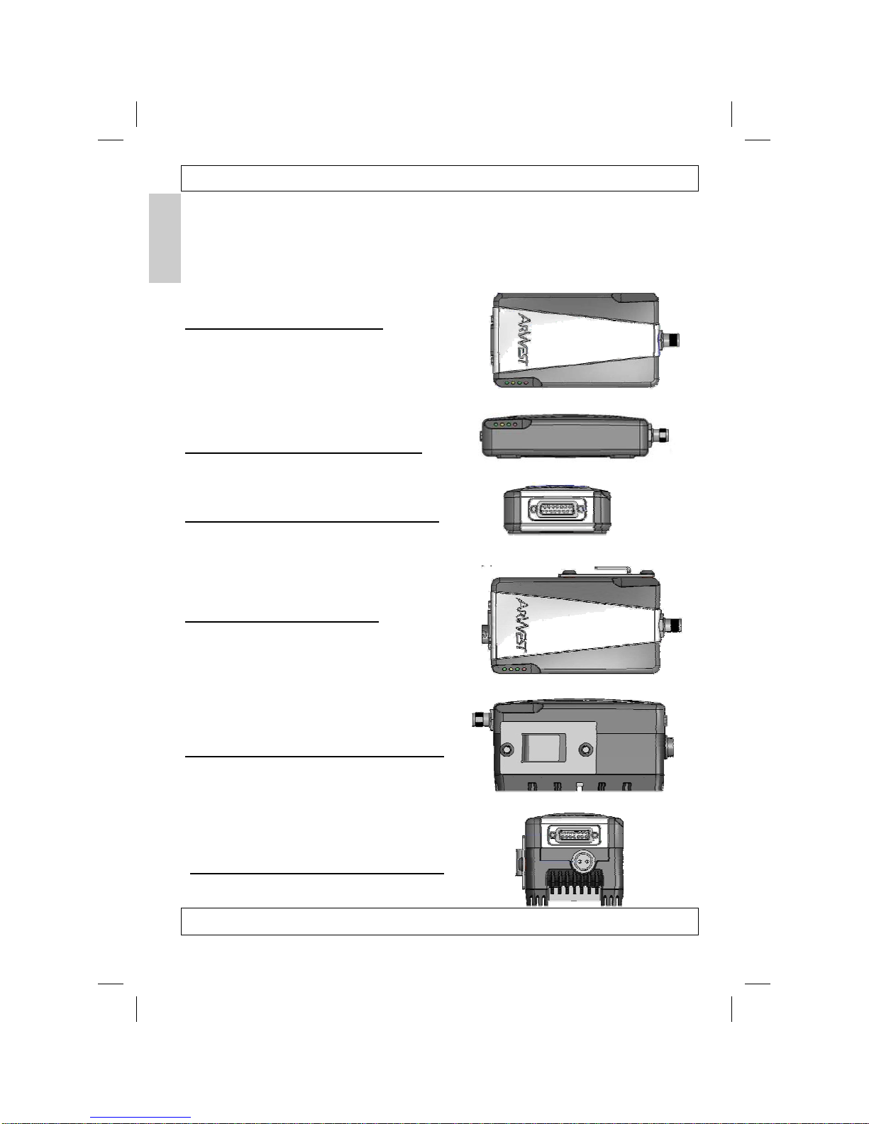
Figure 1-3: AW400 Top View
Figure 1-4: AW400 Side View LEDs
Figure 1-5: AW400 Front View RS232
Figure 1-6 AW435 Top View
Figure 1-7: AW 435 Side View Bracket
Figure 1-8: AW435 Front View RS232
Page 1-6
AlphaWave Users Manual 4/26/2006
Chapter 1
Other manuals for alphawave AW100
2
This manual suits for next models
5
Table of contents


