ASAHI PENTAX S3 User manual
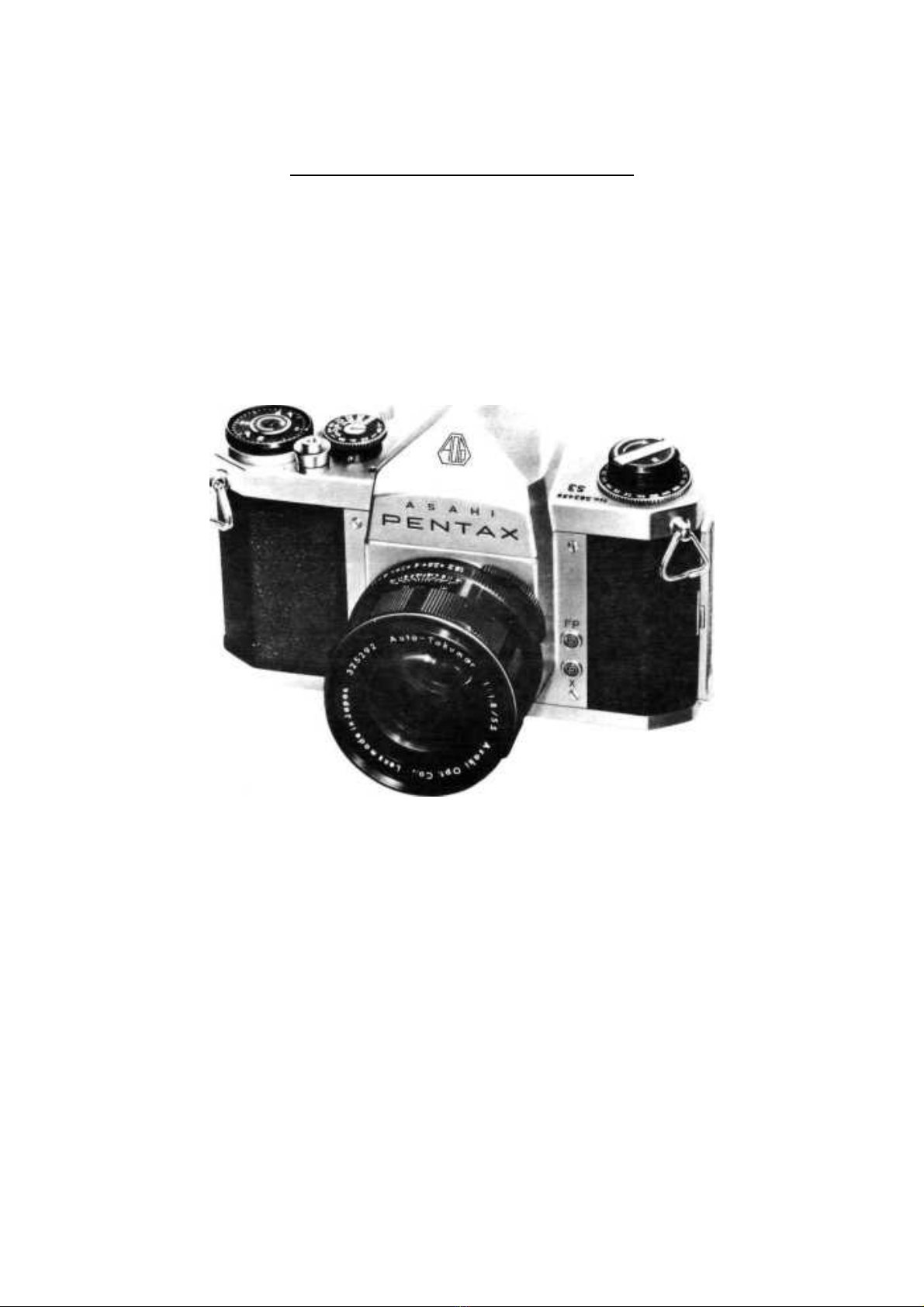
PRODUCT NO.230-2
ASAHI PENTAX S3
SERVICE MANUAL
230-2 -1-

TABLE OF CONTENTS
Page
INTRODUCTION.....................……………………………............................................................... 4
SUMMARY OF STRUCTURE AND PERFORMANCE ......……………………….....................… 4
CHAPTER I. DISASSEMBLY......................................…………………………...................... 8
1. Disassembly of Cover Plates, Rapid Wind Lever and Rewind knob..................................... 8
a. Rapid Wind Lever (C03)
b. Shutter Speed Dial (E23)
c. Rewind Knob (D06)
d. Top Cover Plate (A03)
e. Front Cover Plate (A05)
f. Bottom Cover (A04)
2. Disassembly of Mirror Housing and Optical Parts .........………………………………. 9
a. PrismSeat (B01)
b. Mirror Housing (B02)
c. Mirror (AF12)
3. Disassembly of Top Transport Mechanism..................………………………………… 10
a. Wind-Up Lever Seat (C35)
b. Lever Stopper (C10)
c. Top 1st Gear (C20)
d. Wind-Up Lever Shaft (C34)
4. Disassembly of Bottom Transport Mechanism .......………………………………….... 11
a. Bounce Stopper Actuator I Lever (E98)
b. Coupler Lever (C15)
c. "R" Lever Parts (C70)
d. Pin Adjust Plate (C17)
e. Wind-UpShaft Parts
f. Sprocket Shaft (C30)
5. Disassembly of Shutter Mechanism..............…………………………………................ 12
a. Shutter Gear Mechanism
b. Shutter Curtain Parts
6. Disassembly of Mirror Housing Mechanism .......………………………………….......... 16
CHAPTER II. ASSEMBLY AND ADJUSTMENT ...................…………………................ 18
1. Assembly and Adjustment of Shutter and Transport Mechanism......................................... 19
a. Shutter Curtain Parts
b. Stopper (C1I)
c. Idling Gear Parts
d. Wind-Up Lever Seat (C35) and Top 1st Gear (C20)
e. Bounce Stopper Mechanism
f. Pinion Coupler Lever (E10) and Coupler Lever (C15)
2. Adjustment of Shutter Exposure Timing.......................………………………………….... 29
a. Curtain Speed
b. High Speed Exposure Timing
e. Irregularity of Exposure Timing
d. Slow Speed Exposure Timing
e. Time Exposure
f. Exposure Timing at Various Points on the Picture
3. Assembly and Adjustment of Exposure Counter ....…………………………………........ 34
4. Adjustment of X Contact .....................................……………………………………....... 36
5. Adjustment of FP Contact................................……………………………………........... 37
6. Adjustment of Mechanical Back........................…………………………………............. 37
7. Adjustment of Viewfinder Focus..........................………………………………….......... 38
CHAPTER III. FINAL TESTS..................................…………………………....................... 40
CHAPTER IV. CAUSES OF DEFECTS AND SERVICING.......……………………........... 44
ATTACHMENTS
Listof Special Service Tools
List of Lube Oils
List of Bonds Exploded Illustrations
List of ServiceParts
List of Standard Parts
230-2 -2-

INTRODUCTION
ThisService Manual isprepared for servicing Product # 230 2; however, since the following productshave
structures similar to 230 2. This Manual will also apply to these products:
Product # Model Description Major Difference
229-2 S1. H1. S2. H2 Semi-automatic diaphragm.
230 S3. H3 Old-typefully automatic diaphragm.
229-3 S1. H1. S2. SB. SB2
232 SV. H3v Self-timer, automatic re-setting film counter.
230-3 Sla. Hla, S2 Automatic re-setting film counter.
SUMMARY OF STRUCTURE AND PERFORMANCE
Upon cocking the rapid wind lever, the bounce stopper mechanism isfirst released, the shutter curtains are
wound, and the mirror actuator lever, bottom (B19) tensions the mirror seat spring (B44) and the dia lever
spring (B72).
When the shutter buttonis depressed,the bulb lever will beso positioned as to prevent rotationofthe bottom
selector gear (E44) which is connected with the 2nd curtain, and at the sametime will contact the high speed
cam (E85) which selects the high speed exposure timing. Further, the spill (E08) will comedown, freeing the
top idling gear (E17l, thus making the exposure ready tobe made.
When the shutter button is depressed by 1.2mmto 1.7mm, the 2nd dia lever (B54) will be released and will start
rotating rapidly, and the 1st dia lever (B53) which couples with the 2nd dia lever will press the automatic
diaphragm release pin.
During the rotation of the 2nd dia lever, the reflex mirror isreleased and startsflipping upward. While the
mirror isflipping up, the FP contact isswitched in, and the curtain actuating lever ispressed up, starting the
travel of the 1st curtain.
At the instant the 1st curtain passes the picture format, the X contact isswitched in, and the bounce stopper
functions and then stops.
The shutter exposure timing can be determined by turning the shutter speed dial. The shutter speed dial has a
slot tobe coupled with the Asahi Pentax clip-on exposure meter. As the shutter speed dial isturned, the centre
slot of the high speed cam moves eccentrically, and added to the shape of the high speed cam, high speed
exposure timing isdetermined (from 1/30 to1/1000 sec). Slow speed exposure timing (from 1 to1/15 sec.) is
determined by the slow speed cam (F0l), which changes the operating time of the slow speed governor located
underneath the mirror housing, as the shutter speed dial isturned within the slow speed range.
With the shutter speed dial set at "B" the high speed cam floats, and since the top bulb lever (E06A) does not
contact the high speed cam, the 1st curtain startstravelling when the shutter button isdepressed, however, the
2nd curtain stays without travel. The 2nd curtain will start travelling only after the shutter button is released.
With the shutter speed dial set at "T" the slow speed cam causes the time stopper (F03) tocheck the movement
of the slow speed actuator lever (F06), and contrary to the "B" position, the 2nd curtain will not start travelling
even after the shutter buttonis released, but will start its travel only after the shutter speed dial is turned either to
the direction of "B" or 1/1000.
Just prior tothe completion of travel of the 2nd curtain, the pin of the coupler gear (E18) rotates the pinion
coupler lever (E10), and the bottom actuator lever spring (B47) causes the mirror actuator lever (B19) toreturn
to its original position. As the 1st and 2nd levers are also placed back to the original position, the automatic
diaphragm of the lens reopens again.
Actual time required from the start of the rotation of the 2nd diaphragm lever by depressing the shutter button to
the completion of all these performance is not more than 40 ms. Needless to say, in the case of slow speed
230-2 -3-

exposure timing, the time required will be that much prolonged.
For facilitating better understanding of this Manual as well as for convenience of the reader when making
requisition for interchangeableparts and/or tools, lists and diagramsare attached herewith as Attachments.
Explanations with respect todisassembly are given inthe order of work tobe performed, while those pertaining
to assembly are described inthe order opposite tothe work of disassembly. No explanation isoffered
concerning easily understandable disassembly and, or assembly. In case of a partial disassembly or assembly,
proceed with it on the basis of information contained in this Manual, making reference to such explanations as
may be considered pertinent to such need.
Classification of Part Numbers:
Service part numbers are given always starting with 01, according to each mechanism,and mechanismsare
classified in an alphabetical order as follows:
A Cover Plates, Back-Cover
B Mirror Housing, Prism Seat
C Film Winding Mechanism
D Film Rewinding Mechanism
K Shutter Mechanism
F Shutter Slow-Speed Mechanism
G Slow Speed Governor
AF Optical Parts
Standard Parts:
Service parts commonlyused for allour productsare called "Standard Parts" and the classification isas follows:
WWasher (except for those with special shape)
LW Lock Washer
RRivets(except for those unavailable on the market)
SmallScrews (except for those other than the standard dimensions)
Of the above, index numbers alone are quoted inthe Manualtoindicate standard smallscrews for the sake of
brevity. However, the index numbers shown are those applicableonlytothis Manual for 230-2, and should
therefore never be quoted, say, when making requisition for service parts or in technical communication.
Attachment 5 -- List of Service Parts -- may be modified or revised when alterations or improvement insomeof
the listed items are deemed necessary, or when assembled parts are altered for various other reasons.
Please note, however, when such alterations ormodifications are initiated,a new complete List ofService Paris
or a notice thereof will bemailed to you.
230-2 -4-

CHAPTER I. DISASSEMBLY
NOTE: As red lacquered spots are the spots securelyfixed after making necessary technical adjustment,
do not unscrew such spots unnecessarily. When removing springs, care must be exercised so as not to
give any deformation tothe springs; also refrain from taking out springs with bare fingers.
1. Disassembly of Cover Plates, Rapid Wind Lever and Rewind Knob.
a. RAPID WIND LEVER (C03)
Take out the arrow ring retainer screw (C54). When the counter screw (C36) isremoved, using special
tool No. 225K-C36-A, the counter (C12) and counter spring (C60) can be taken out.
When the actuator lug screw (C53) for the advance lug actuator (C07) istaken out, 2 screws (C73) for
(C03) can be removed. As (C03) is securely fixed with a binding agent to the upper surface of the wind-
up lever seat (C35), dissolve the binding agent,using such solvent as Methyl-ethyl-ketone or Acetone,
before attempting toremove the screw. Remember that inour current productsa binding agent isused
not on the surface of the wind-up lever seat (C35) but on the rapid wind lever retainer screw (C73).
b. SHUTTER SPEED DIAL (E23)
With the shutter dial set at " B," remove 3 small screws (23) andyouwill findit easier to perform
disassembling.
c. REWIND KNOB (D06)
With a screw driver ora similar tool inserted into the fork ofthe rewindshaft (D05), which goes into one
end of a film cassette, rotate the crank (D10) counter-clockwise more or less forcibly and unscrew it. If
the flat nut (D09) istaken out, using special tool No. 225K-D09-A, the film type dial washer (D02) and
film typedial (D08) will come out simultaneously.
d. TOP COVER PLATE (A03)
Take out 1 screw (18) on the upper side of the top cover plate (A03) and then 2 screws (19) on both sides
of the finder eye-piece and push the plate strongly upward.
e. FRONT COVER PLATE (A05)
Remove 4 screws (19) andyouwill findthe front cover adjust washer (A39) between the front cover
plate (A05) and the body proper (A01); this isintended for the mechanical back tobe 45.46mm. In the
event (A05) is not replaced, fix the plate at time of reassembling to its original place, and correct
dimensions can be maintained without making adjustment.
f. BOTTOM COVER (A04)
Remove 2 screws each (18) and (16).
2. Disassembly of Mirror Housing and Optical Parts.
a. PRISM SEAT (B01)
Take out 3 screws (13) by tightly holding the prism seat (B01) with fingers toprotect itfrom floating by
the elasticity of the ground glass holder (B79). The prism (AF17) should not be dismantled from the
prism seat (B0l) as far as possible, but when itistobe removed, unscrew either one of the 2 adjustment
screws (21).
b. MIRROR HOUSING (B02)
Unloose the screw (I) of the lug plate (B77) at X contact on the bottom part of the body proper (A0l),
slowly correct the cord B (B73) with tweezers to make it straight, remove 2 screws (11) and 2 screws
(B71) and take out the mirror housing (B02) slopewise frontward. While taking the mirror housing out,
push itinthe direction of B02 so as not tolet the curtain actuator lever IB20I hook up the body proper
(A01). Care must also be exercised not tolet the cut opening of the mirror actuator lever, bottom (B19),
hook up the edge of either the coupler gear (E18) or the coupler lever (C15).
c. MIRROR (AF12)
Press inward the front edge of the mirror (AF12), say, with the tip of tweezers, and 2 front claws of the
mirror retainer plate (B12) will come off, thereby floatingthe mirror.
230-2 -5-

NOTE: Never touch the surface of the mirror with a fingertip or any kind of tool. If the mirror gets
dusty, use a soft brush or a blower todust itoff.
3. Disassemblyof Top Transport Mechanism.
a. WIND-UP LEVER SEAT (C35)
Press the edge of the spring (Cl9) with finger toprevent itfrom recoiling, and then take out (C35) from
the wind-up lever shaft (C34), after which if(C19) isproperlyfixed to(C 35), using shape wire, the
trouble of recoiling the spring can be dispensed with at time of reassembling. (Diagram 1)
NOTE: When recoiling (C19), do itwith gloves on. If handled with bare fingers, the spring trends tobe
rusted.
(Diagram 1)
b. LEVER STOPPER (Cl0)
Take out 2 screws (15) and 2 stopper washers (C68).
c. TOP FIRST GEAR (C20)
Prior totaking out the top 1st gear (C20), mark the body proper (A01) with a dot, indicating the spot
extended from the corner of either one of the two projected points and an accurate angle can be easily
determined when reassembling. (Diagram 2)
(Diagram 2)
Mark here with a dot
d. WIND-UP LEVER SHAFT (C34) Unloose 3 screws (17).
4. Disassemblyof Bottom Transport Mechanism.
a. BOUNCE STOPPER ACTUATOR LEVER (E08)
Remove the bounce stopper lever screw (E103) and ease the bounce stopper actuator lever screw (E100)
and take out;he bounce stopper lever (E99) and bounce stopper spring (E102) with particular attention to
the washer W3—located beneath (E98).
NOTE: When (E98) is removed, (E99) must also be taken out, because once (E98) is dismantled, (E99)
is invariably placed in a position where the bounce stopper mechanism is at work, and if, by any
chance, the shutter is cocked, the 1st curtain will thereby very likely bedamaged.
b. COUPLER LEVER (C15)
Remove the coupler lever retainer screw (C80).
230-2 -6-

c. "R" LEVER PARTS (C70)
As the "R" button isscrewed in, remove itby turning itcounter-clockwise
forcibly with finger. When the "R" lever retainer screw (C52) is taken out,
the "R” lever spring (C62), "R” lever (C70), W9and bottom 1st gear (C25)
will come out fromthe lower bottom1st gear shaft (C46).
d. PIN ADJUST PLATE (C17) Remove the screw (14) and then unloose 2
screws (23).
e. WIND UP SHAFT PARTS
Press the top main gear (C23), using special tool No. 225K C23 A, and take
out the bottom main gear (C24) by turning itcounter-clockwise and thereby
unscrewing it, using special tool 225K C24 A. (Diagram 3)
NOTE:
1. Do not turn (C23) counter-clockwise under any circumstances.
2. W17(s) located at the upper and lower parts of the spool brimare intended for adjusting the weight of
load on the rotation of the spool, inview of which their number and location have tobe remembered.
The wind-up shaft bearing (C32) should be taken out along with the wind-up shaft (C 31) by
loosening 3 screws (17), and then the top take-up spool brim(C13), the bottom take-up spool brim
(C14) and the take-up spool shaft (C33) will comeoff.
REFERENCE:
The center diameter of (C31), insomecameras, isfound narrower for itisintended tolighten the
camera weight and should be considered as an improvement.
f. Sprocket Shaft (C30)
Take out the coupler lever seat (C16), sprocket seat spring (C63) located beneath the seat, and then the
sprocket cover (A06). Unloose the sprocket screw (C56), and the bottom 3rd gear assembly (0C27) can
be easily taken out from the body proper.
5. Disassembly of Shutter Mechanism.
NOTE: When disassemblingthe shutter mechanism,close attentionmust bepaid to the couplingrelations
and locations of various gears.
a. SHUTTER GEAR MECHANISM
(1) Pinion Coupler Lever (E10)
Unloose the pinion coupler lever retainer screw (E52), and (E10) and the underneath washer (W2) can be
taken out.
(2) Coupler Gear (E18)
Unloose the coupler gear retainer screw (E53), and (E18) can be taken out together with the underneath
washer (W3)
(3) Coupler Pinion (E13)
Insert a driver through the cut-opening located at the back of the bottom part of the body, unloose the
coupler pinion screw (E88), and forcibly pullitout from the 2nd curtain pinion shaft (E32).
NOTE:Care must be exercised not topress the driver too hard; otherwise (E32) might be bent.
(4) Shutter Rod (E29)
Remove the actuator rod (E30) by turning itcounter-clockwise. Remove LW17 from the idling gear
retainer screw (E50), and then (E30) can be taken out upward from the body proper.
REFERENCE:
In the event the idling gear parts alone are tobe taken out for disassembling or washing purposes, do not
go through the trouble of removing the mirror housing or the shutter rod (E29); just remove the release
230-2 -7-
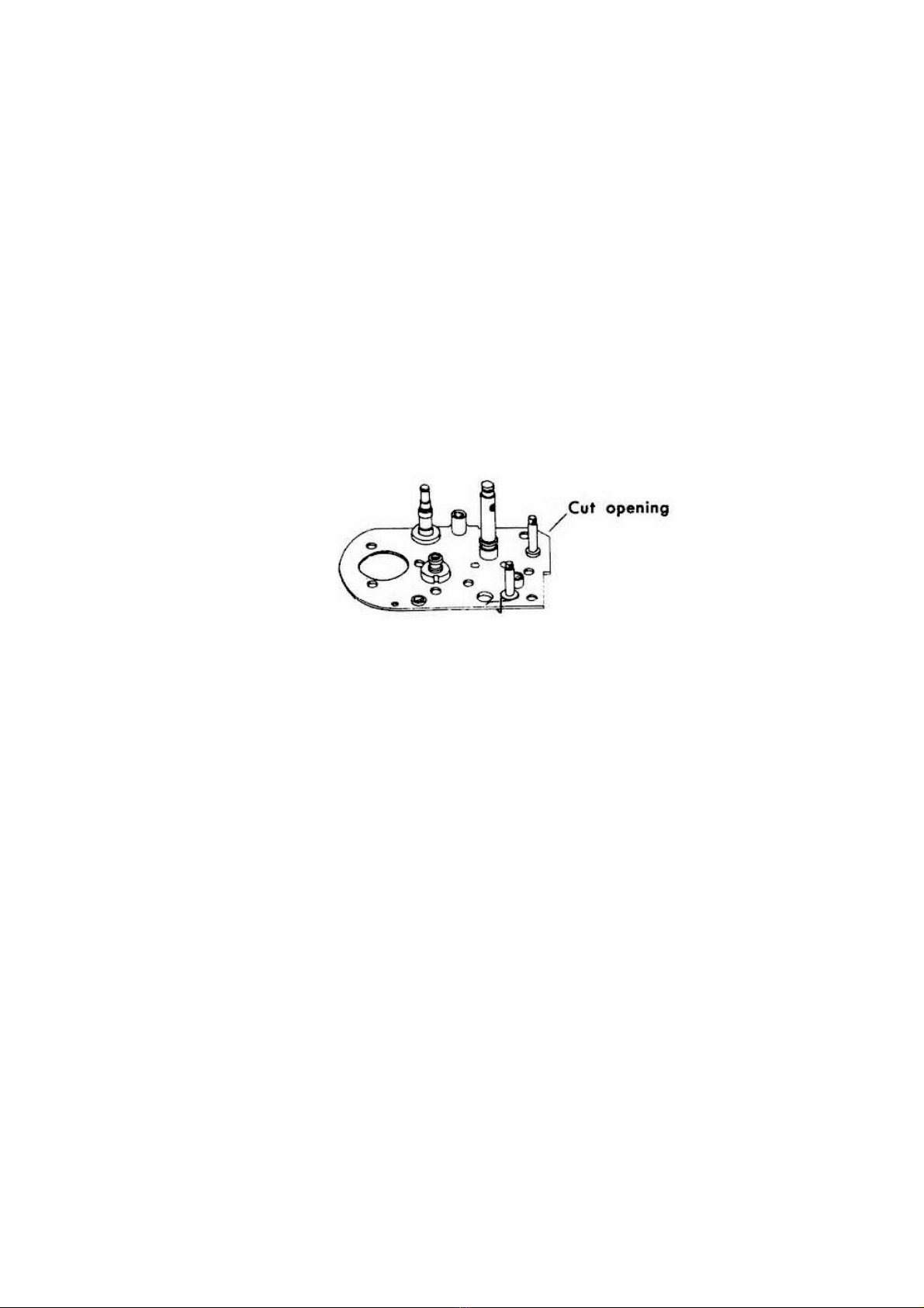
plate (E05) by loosening the release plate nut (E119), and the desired parts can be taken out.
(5) Slow Speed Rod (F12)
Ease the cam coupler plate nut (F11), using special tool No.225K-FII-A, remove the cam coupler plate
(F02). Then remove LW13, intended tocheck up-and-down movement of the slow speed rod (F12), and
the governor at the bottom of the body proper and its coupling parts can be taken out at the sametime in
one body from the bottom parts of the body proper.
(6) Speed Selector Disc (E68)
Take out the index ring (E24) from the speed gear shaft by unloosening 3 screws (23), and (E68) can be
also removed.
(7) Unloose 2 screws (9) for the click spring (E83), and itcan be taken out along with the light seal (C87).
REFERENCE:
The light seal (C87) began tobe installed in230 2 at a later stage of production for the following reasons:
For Product No 232 (with self-timer), a top mec. plate (C01) with a cut opening isused inview of its
mechanical structure, and (C87) is accordingly installed for the purpose of insuring complete prevention
of light leakage. As, however, a change was effected tomake use of (COD for 230-2 for 232 as well.
(C87) was added.
Consequently, ina case where (C0l) isdevoid of any cut opening, (C87) isnot required. (Diagram 4)
(Diagram 4)
(8) High Speed Cam Parts
Ease the selector shaft tube retainer screw (E117) and remove the selector collar (E25) from the selector
gear shaft (E26), and the high speed cam (E85) parts, the cam shaft spring (E56) and the cam shaft spring
receptacle (E79) can be taken out.
For disassembling the high speed cam parts, namely, (E85), cam shaft (E69) and cam shaft nut (E76), use
special tools No. 230K - E69 A and No. 230K - E76A.
(9) Bulb Lever Paris
By easing the bulb lever nut (E48), the bulb lever parts can be taken out ina body from the bulb lever
shaft (E27).
NOTE:Before attempting toremove the bulb lever parts, see toitthat the bulb lever spring (E62) is
dismantled fromthe bottomBulb lever (E06B).
(10)Idling Gear Parts
When the idling gear retainer screw (E50) isremoved, the idling gear parts located beneath it, viz., the
spill receptacle plate (E09), top idling gear (E17), spill (E08) and bottom idling gear (E16) can be taken
out. Makesure to remove the spill rest (E21) beneath (E16) andthe spill spring(E58) at the sametime as
these are liable to be lost.
(11)Stopper (C11)
Ease 1 screw (12) and stopper nut (C92), and the stopper (C11) can be removed.
NOTE: Once the stopper (C11) isremoved, the pinion rotates freely, thereby tending the shutter curtains
to strip off the shaft. Consequently, before attemptingto remove C11, see to it that the tensionofthe
shutter curtain spring is weakened. (Refer to 5. b. 1.)
REFERENCE:
When the shutter curtains, 2nd curtain pinions (Ell) (E12), bottom selector gear (E14) and top
selector gear (E15) are not to be replaced with new ones, mark the exact coupling positions of the
gears before removing (C11) for the purpose of facilitating reassembling. (Diagram 5)
230-2 -8-

Diagram 5
b. SHUTTER CURTAIN PARTS
NOTE: When attemptingto overhaul the shutter curtain parts, strict care must be exercised not to tear off
the curtain from the pipes; not to make a hole in the curtain with such tool as tweezers; and not to
stain them with oil.
(1) Curtain Spring Adjust Gear A (E92)
Put a driver into the slotofthe curtain springadjust gear A (E92i to prevent its rotation, takeout the
curtain spring adjust lug (E42) from the gear, and then turn the driver slowly clockwise, thereby placing
the curtain spring back toits original position with no tension. For overhauling (E93), the same
procedure may be followed.
NOTE: The curtain spring should never be placed back to its original position rapidly. Put a driver into
the upper slot of the 1st curtain shaft (E33) toprevent its movement, and turn (E92) clockwise,
unloosening the screw totake itout. The curtain spring adjust gear B (E93) should also be
overhauled inexactly the samemanner. Remember that (E92) and (E93) screw counter-clockwise.
(2) Sync. Gear (E104)
If LW13 ispulled out of the sync, gear column (E105), (E104) can be removed.
(3) Top Shaft Plate (E01)
When 2 pcs of LW13 and 2 pcs of screw (72) are removed, the curtain pipes and shutter curtains can be
taken out ina body from the body proper.
(4) Top Mec Plate (C01)
Ease the 1st curtain checker arm stopper (E86) and stopper column (C42), and the 1st curtain pinion
shaft (E31) and 2nd curtain pinion shaft (E32) can be taken out ina body from the body proper.
(5) Top Mec. Plate (C01) and Shutter Curtains
Ease 3 pcs of pinion shaft retainer screw (E55) and the 1st,and 2nd curtain pinion shafts(E31) (E32) can be
pulled out of (C01).
6. Disassembly of Mirror Housing Mechanism.
NOTE: Overhauling of the mirror housing mechanism may be made from any parts you desire, but the
following points must be borne inmind:
(a) Do not turn the red lacquer sealed 2nd dia. lever adjust screw (B59), because this screw is
adjusted tocause the rotation of the 2nd dia. lever (B54) when the shutter bottom isdepressed to1.2
- 1.7 mm.
(b) Do not ease the mirror seat rest screw (B13) which retains the mirror seat rest (B14). The
(B14) is properly adjusted to maintain the mirror at the correct 45° angle whenever it is down.
(c) Remember well the exact location of the washers located in between the mirror actuator
lever, top (B18), mirror actuator, bottom (B19) and mirror actuator lever shaft (B35), as the
washers are adjusted to prevent clearance of these parts.
230-2 -9-

CHAPTER II. ASSEMBLY AND ADJUSTMENT
In this Chapter II, photographs are shown, besides diagrams, inthe order of assembling, where considered
helpful. For instance, photo No. 3 shown under 1. b, illustrates the assembled condition up to the stage of the
stopper (C11).
NOTE:Disassembled parts, before assembling, need a careful washing and or dusting with either a piece of
cloth or a blower. When servicing customers' cameras, discretion, of course, has tobe exercised in
this respect, taking into consideration such factors as the model,period of use, nature of defects, etc.
However, the general rules are summarized below:
Parts equipped with rotating shafts and or shaft bearings have to be thoroughly washed with quality
gasoline or benzene. Especially such parts as are to be lubricated with "L" lubricants need a careful
washing and drying. However, pipes and governor parts containing curtains or springs should never
be immersed incleaning liquid for washing purposes.
Exposed plated and anodised parts should be thoroughlywiped either with a brush or with a clean
piece of cloth. When stains are found, lightly wipe off the stained parts with a clean piece of cloth
soaked with liquid composed of ether and alcohol at the ratio of 60% and 40%.
Painted parts need only be lightly dusted with a brush. Stains on the outer surface of black cameras
should be wiped either with silicon-cloth (similar to the one usually used for wiping glasses and is
easily available on the market! or with the aforementioned liquid composed of 60% ether and 40%
alcohol, very lightly so as not toerase the white letters engraved on the cameras.
For wiping optical parts, mixed liquid comprising 70% ether and 30% alcohol should be used. In this
connection, a clean piece of cotton or hempcloth, properly washed beforehand and entirely devoid
of starch, or a piece of soil paper is recommended for use.
For wiping parts made of plastics (such as Fresneland ground glass), use mixed liquid composed of
50% ether and 50% alcohol, which gives satisfactory results.
The mirror should never be wiped with a piece of cloth under any circumstances. If wiped with such
material, itresults inflaws. Dusts or dirts on the mirror need tobe blown with a blower.
It isof utmost importance toabide by the instructions governing the right kind of lubricants,
lubricating positions and lubricant quantity. Lubrication needs to be performed strictly in accordance
with Attachment 2—List of Lube Oil —as wrong use of oil will invariably result in the deterioration
in performance or functioning of various parts and may cause defects.
1. Assembly and Adjustment of Shutter and Transport Mechanism.
a. SHUTTER CURTAIN PARTS
(1) After the shutter curtain parts are assembled,slowly rotate 2 or3 times the 1st curtain shaft (E33)
and 2nd curtain shaft (E94) clockwise totension the curtain springs. (Diagram 6) Final adjustment of the
curtain spring tension should be made at the time of adjusting the curtain travel speed mentioned
elsewhere.
Diagram 6
230-2 -10-
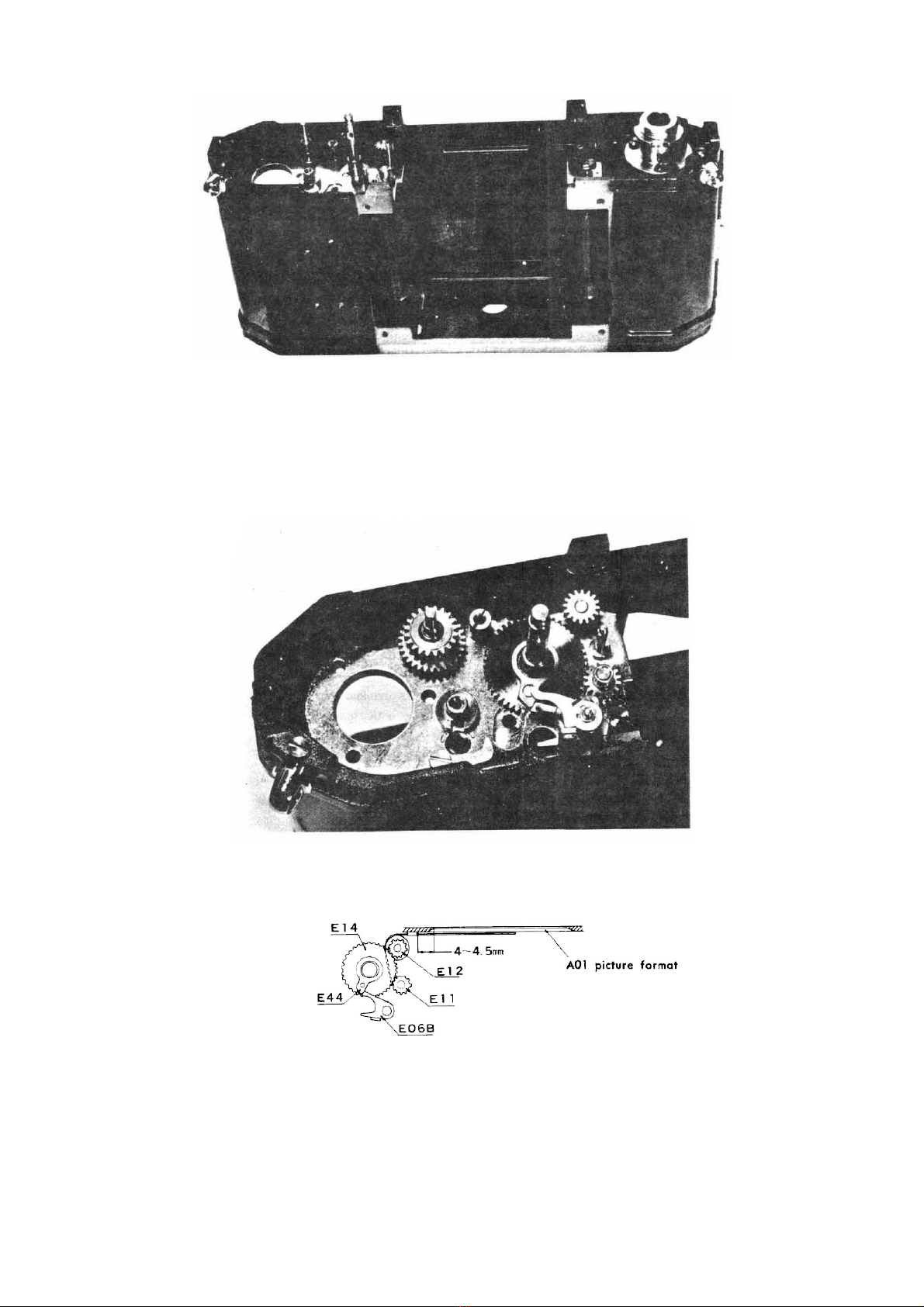
Photo 1
(2) Relative position of the shutter curtains and the bottom selector gear (E14), after assembling (E14) with
bulb lever parts, should be determined by gearing (El4) with (Ell) in the wound-up condition of the
shutter curtain as illustrated in Diagram 7.(E14) andthe pinion shaft need oiling.
NOTE: When resetting the shutter curtains tothe un-cocked condition, do itslowly. (Diagram 7)
Diagram 7
(3) After the top selector gear (El5) ismounted, the location of the 1st and 2nd curtain edgers (E03, E04)
should be adjusted as illustrated in Diagram 8. For winding the shutter curtains, use special tool No.
229K-E64, E65--A, and you will find the job easier.
230-2 -11-

Diagram 8
Location must be adjusted the tolerance of
0.5mm
b. STOPPER (C11)
After installing the 1st curtain checker arm (E07) and the stopper (C11), the gap between the projected
point of the selector gear stopper (E77) and (C11) should be adjusted tobe 0.2-0.3 mminthe cocked
condition. Thisadjustment should be made by turning the screw (22) which isscrewed inthrough the
back of (A01). (Diagram 9)
Diagram 9
Photo 3
c. IDLING GEAR PARTS
NOTE: Read carefully the following instructions and utmost caution should be exercised when adjusting
this part which is delicate in nature.
When installingthe winding shaft parts, spill spring(E58), spill rest (E21), bottomidlinggear (E16)
andspill (E08), slowly rotate clock-wise the topmain gear retainer screw (C75) first with a driver,
while pressing downward (EOS) with the tip of tweezers. When the spill (E08) comes above the
groove of the idling gear shaft (E20), itfalls into the groove, pushed against the direction of the
rotation of the various gears, preventing them from rotating. (Diagram 10)
-
Diagram 10
230-2 -12
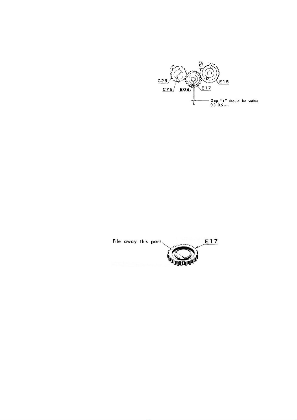
Ease the force of (C75) and also the pressure on (E08), and the top main gear (C23), (E16) (EOS)
slightly turn backward with the tension of the wind-up shaft spring (C57); then the non-return arm (C04)
springs into the groove underneath (E16) and then stops. While maintaining this position, fix the top
idling gear (E17), paying careful attention to "t". (Diagram 11)
Diagram 11
Then putting on the spill receptacle plate (E09) and screw in with the idling gear retainer screw (E50).
NOTE: A tiny quantity of oil should be applied on (E20).
In a similar manner as described above, turn the top main gear retainer screw (C75) with a driver
until the selector gear stopper (E77) collides against (C11), then relax the force of the driver. The
idling gear part will then move backward slightly and stop in a manner as described above.
At the sametime, the pin of the top selector gear (E15) comes toa stop, running against the tip of
(E07). Then slowly press downward the spill (E08); andif (E08) smoothly goes upanddown, proper
adjustment has been completed.
If the gap "t" shown inDiagram 11 istoo big, (E08) goes beyond the groove of (E20), iftoo small,
it will not reach the proper position, colliding against the brink of the groove, or resulting in creak,
when (E08) ispressed
In the event (E17) is replaced with a new one, if the groove of (E17) cannot be so properly
positioned even though the engaging position of the gears is changed, the groove needs adjustment
by filing with a fine file. (Diagram 12)
Diagram 12
NOTE: Before assembling (E17), oil or dirts in the hole, its surface and on the parts contacting (E09)
must be thoroughlycleaned and removed. Otherwise, exposure time of the shutter isliable toremain
unstable.
230-2 -13-

Photo 4
REFERENCE:
How tomake adjustment ifthe pin adjust plate (C 17) isof the old type:
In the case of (C17) of the old type (prior tothe introduction of the improved one), the range of
adjusting the position of the coupler lever pin (C51), after completion of the adjustment of the idling
gear, is slight; and accordingly, (E16) should be fixed along the groove of (E20), after correctly
positioning (C51) by turning (C75). Needless tosay,itispossible tomake a slight adjustment of the
position of (C51), even if(CI7) isof the old type.
(Old Type)
Diagram 13
(Improved Type)
Photo 5
d. WIND-UP LEVER SEAT (C35) AND TOP FIRST GEAR (C20).
Tightly screw the wind-up lever shaft (C34) and affix (C20) tothe shaft.(As explained inChapter 1, 3 c,
(C20) may be correctly positioned ifmatched tothe mark properlymade beforehand.) Fix the lever
stopper (C10), (C35) and the rapid wind lever (C03), and cock the lever fC03) thoroughly. When (C03)
is cocked completely, if the projected part of(E77) collide against (C11) and(C35) to the projected part
of (C10) simultaneously, or else the latter has an opening tothe extent of 0.2 mm, proper adjustment
may be saidtohave been completed. (Diagram 14)
-
230-2 -14
Diagram 14

In the event a wide gap has been created on either parts, lift the top 1st gear (C20) and change its
engaging position with that of (C21). In the event any one of the gears on the upper part of the body
proper has been replaced, proper adjustment of the aforementioned gap may sometimes be found
impossible. In such a case as this where a delicate adjustment is called for, 5 kinds of the lever seat lug
(C05), each different in length, are available.
Diagram 14 C05-1 C05-2 C05-3 C05-
4
C05-5
The Longest The
Shortest
NOTE: If (C10) and/or (C35) are filed off for the purpose of adjusting the gap, the rotating angle of
(C03) changes, inconsequence of which itsometimes becomes extremelydifficultor impossible
to adjust the counter assembly which istobe fixed on it.
Photo6
e. BOUNCE STOPPER MECHANISM
(1) When fixing the pin adjust plate (C17) tothe bottom main gear (C24), determine the position of the
coupler lever pin (C51) and fasten the screws (14) and (23). ((Refer toDiagram 13.)
(2) The relative position of the bounce stopper lever (E99) tothe sync gear (E104) istobe adjusted as
per Diagram 16. Upon completion of the adjustment, cock the shutter toensure that the bounce
stopper (E97) will rotate smoothly without hooking up the bounce stopper lever (E99) at the initial
stage of cocking.
Diagram 16
Photo 7
230-2 -15-
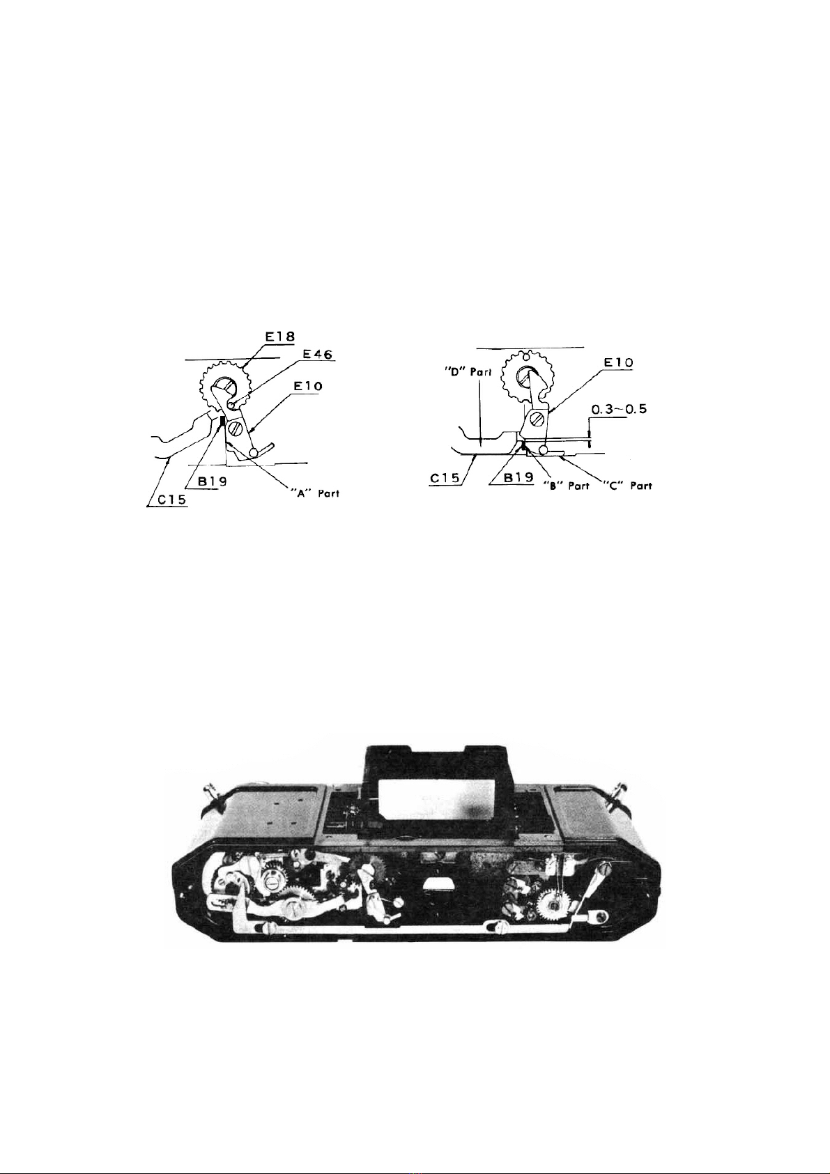
f. PINION COUPLER LEVER (E10) AND COUPLER LEVER (C15).
After fixing the mirror housing assembly (0B02) and (E10) tothe body proper, the following adjustment
has tobe performed:
(1) Adjustment of (E10)
The "A" part of (E10), before shutter rocking, issupposed tobe inparallel with the groove of the
body proper checked by the coupler gear stud (E46) of the coupler gear (E18) as shown inDiagram
17-A; and the position of (E46) istobe determined by the half-moon shaped slow speed lever
actuator stud (E45). (Refer toDiagram 19.) When the shutter iscocked, the "B" part of (E10) should
be so positioned as toslightly pass the brink of the groove of the body proper. In the event this
position is found unattainable, bend the "C" part of (E10) with pliers for necessary adjustment.
(Diagram 17-B)
A
Diagram 17
B
(2) Adjustment of (C15)
Before the shutter iswound, the tip of the mirror actuator lever, bottom (B19), islocated close to(E18).
In the course of winding the shutter, itslides along the groove of the body proper, forced by the tip of
(C15). When (B19) ispositioned closest tothe back of the body proper, the gap between (B19) and
(E10) should be adjusted tobe within 0.3-0.5 mm. Thisadjustment istobe performed by bending the
"D" part of (C15) with a pairof flat-nose pliers. (Diagram l7-B)
NOTE: In case (C15) is bent toomuch, (B19) will collide, duringthe course of winding, against the back
of the body proper, resulting in heavy winding or failure in cocking.
Photo 8
2. Adjustment of Shutter Exposure Timing.
After installing the speed dial (E23), the shutter exposure time istobe adjusted inthe following order.
However, covers such as (A03). (A04) and (A05) should be left unassembled.
230-2 -16-
(1) Adjustment of curtain travel speed.
(2) Adjustment of high speed exposure timing (l/1000 sec-1/30 sec.).
(3) Adjustment of slow speed exposure timing (1/15sec.- 1 sec.)
a. CURTAIN SPEED
The curtain travel speed isthe time required for the shutter curtains torun through the picture format (36
mm). In this model,the speed isadjusted tobe 16.5 +/- 0.3 msunder the ambient temperature of approx.
20oC.
The adjustment has tobe performed inthe following order:
(1)Set the speed dial (23) at 1/1000.
(2) Disassemble the curtain spring adjust lug (E42) from the curtain spring adjust levers A and B (E92)
(E93), and slowlyput the curtain spring back toits original free-of-tension position (in the event it
was wound 2 or 3 times when installing the curtain assembly).
(3) Tension the curtain spring by rotating (E92) 5 times, and (E93) 7 times.
(4) By adjusting the curtain spring, make necessary adjustment of the curtain travel speed so that it
comes within the tolerance ofthe aforementioned value.
b. HIGH SPEED EXPOSURE TIMING
High speed exposure timing is to be adjusted by changing the width of the slit formed by the 1st and 2nd
curtains. Ease the bulb lever adjust nut (E87) using special tool No. 225K E48-A, and ifthe screw (20)
is turned clockwise, the exposure timing will be faster; if turned counter-clockwise, the exposure timing
will beslower.
First, adjust the exposure timing for 1/125 sec. (8 ms) and 1/60 sec. (17.8 ms) totheir rating or nearest to
it. Then turn the speed dial to1/1000 sec. (1 ms) and 1/500 (2 ms) for measuring purposes, and repeat
this procedure until satisfactory exposure timing is obtained. Once the above mentioned exposure timing
is determined, exposure timing for the other speeds may be determined automatically by dint of the high
speed cam (E85). Lastly, (E85) should be sealed with red lacquer. (Diagram 18)
Diagram 18
In the event the shutter curtains, high speed cam and bulb lever parts are not replaced, correct exposure
timing may be obtained merelyby adjusting the curtain travel speed, without adjusting the screw (20).
c. IRREGULARITY OF EXPOSURE TIMING
If the exposure timing differs each time the shutter is released, it is called "irregularity of exposure
timing." Strictly speaking, itisextremelydifficulttomaintain exposure timing entirelyfree of
irregularity. However, major causes (or irregularity may be traced to the following:
(1) When the top idling gear isoiled or stained.
(2) When the high speed cam (E85) isdusted and or not properlyoiled.
(3) When the bottom selector gear (E14) isnot properlyoiled.
(4) When the 1st, 2nd curtain pinion shafts (E31) (E32), and the shaft receptacle parts of both top and
bottom mec plates (C01) (C02) are not properlyoiled.
(5) When the curtain roller metal made of brass (E37) isnot properlyoiled.
NOTE: No oiling isrequired where plastic material isused.
230-2 -17-

d. SLOW SPEED EXPOSURE TIMING
Slow speed exposure timing can be determined by adjusting the exposure timing for 1/15 sec (6.7 ms),
and the exposure timing for the rest (1/8-1 sec) may be determined automatically by dint of the slow
speed cam (F01). Better stability of the exposure timing can be expected if the timing for 1/15 sec is
adjusted so as tobe very slightly prolonged, viz., 7-8 ms.
First, see to it that the contact between the slow speed lever (F07) and the slow speed lever actuator stud
(E45) of the coupler gear (E18) ismade closer tothe entrance of the opening of the governor assembly
(0G00). In other words, adjust and set the shutter exposure timing to be a little faster than 1/15 sec and
then attempt toarrive at the correct exposure timing gradually by means of repeated measuring, and you
will find this method easier for making necessary adjustment. The procedures are detailed below in the
order of work: (Diagram 19)
(1) Slightly ease the adjust plate screw (F18) (left-handed screw) and the screw (5), and rotate the top
adjust plate (F05) counter-clockwise until it reaches the lip of the screw (5).
(2) Slightly fasten the adjust plate screw (F18) to such an extent as to make (F05) rotate chafing against
the bottom adjust plate (F04) when the screw (5) is turned.
(3) Turn the screw (5) clockwise slightly togive a push to(F05).
(4) Measure exposure timing.
(5) Repeat the procedure of 3 and 4.
(6) When the timing reaches the allowable tolerance of 7-8 ms, tightly screw in (F18).
(7) Make final measurement.
(8) Seal tightly the screw (5) with red lacquer.
Diagram 19
e. TIME EXPOSURE
(Diagram 20)
When the shutter is released with the shutter speed dial set at "T," the 1st curtain completes its
travel, but projected part of the slow speed actuator lever (F06) hooks with the time stopper
(F03), thereby preventing the 2nd curtain from starting its travel.
When the shutter speed dial isturned to"B" or 1 1000, (F06) moves tothe left by dint of the slow speed
cam (F01), separating from the stopper (F03), causing the 2nd curtain tostart its travel, thereby making
time exposure complete.
During the time pace of 1.15 1 sec, (F06) actuates to the extreme right, when the speed dial is set at 1
sec. At this instant,the projected part of (F06) must actuatewithout contacting (F03). Bearing inmind
what has been described above, itisessential toadjust (F03) by easing the screw (3).
230-2 -18-

Diagram 19
f. EXPOSURE TIMING AT VARIOUS POINTS ON THE PICTURE FORMAT.
In a camera with focal plane shutter, the slit formed byits shutter curtainstravels right in front ofthe
picture format, thereby providing exposure on the film successively. In view of this, it becomes
necessary tomeasure the time of exposure at various points on the picture formal.
In this camera, the adjustment of the above exposure timing should be made at 1/1000 sec. If the travel
time of the shutter curtains at 1/1000 sec. isconsistent and the time of exposure at various points within
the picture format islikewise satisfactory,itfollows that exposure timing at the slower speeds isgood as
a matter of course.
An ordinary shutter gauge indicates the time of exposure at 3 positions, viz., at starting end, at center
and at finishing end of the picture format.
In view of the characteristics of this camera, itisdesirable toadjust the exposure time so as tomake itat
the former end of the format slightly faster than at center, and to make it at the latter endas fast as, or
slightly slower than, at center.
By carefully comparing the time of exposure at 3 different positions as indicated by a shutter speed
tester, discretion has tobe exercised whether toadjust the curtain speed or the bulb lever. The time of
exposure at the former end has tobe adjusted with the bulb lever, while that at the latter end with the
curtain travel speed. However, since adjustment of either of the above parts changes the time of
exposure at the 3 different positions, compare the exposure at the former and latter positions and repeat
the above adjustment procedures until satisfactory results arc obtained. An example in this respect is
shown inDiagram 21.
REFERENCE:
The time of exposure usually referred tomeans time of exposure at the center of the picture
Diagram 21
3. Assembly and Adjustment of Exposure Counter.
No adjustment is required when no parts are replaced. In the event someparts are replaced, assembly and
adjustment have tobe performed inthe following order:
Fix the top cover plate (A03), and then the rapid wind lever (C03), followed by the cover ring (C39). The
procedure up to this stage is mechanical.
Then the advance lug actuator (C07) has tobe tightly secured with the actuator lug screw (C53). With (C03)
230-2 -19-
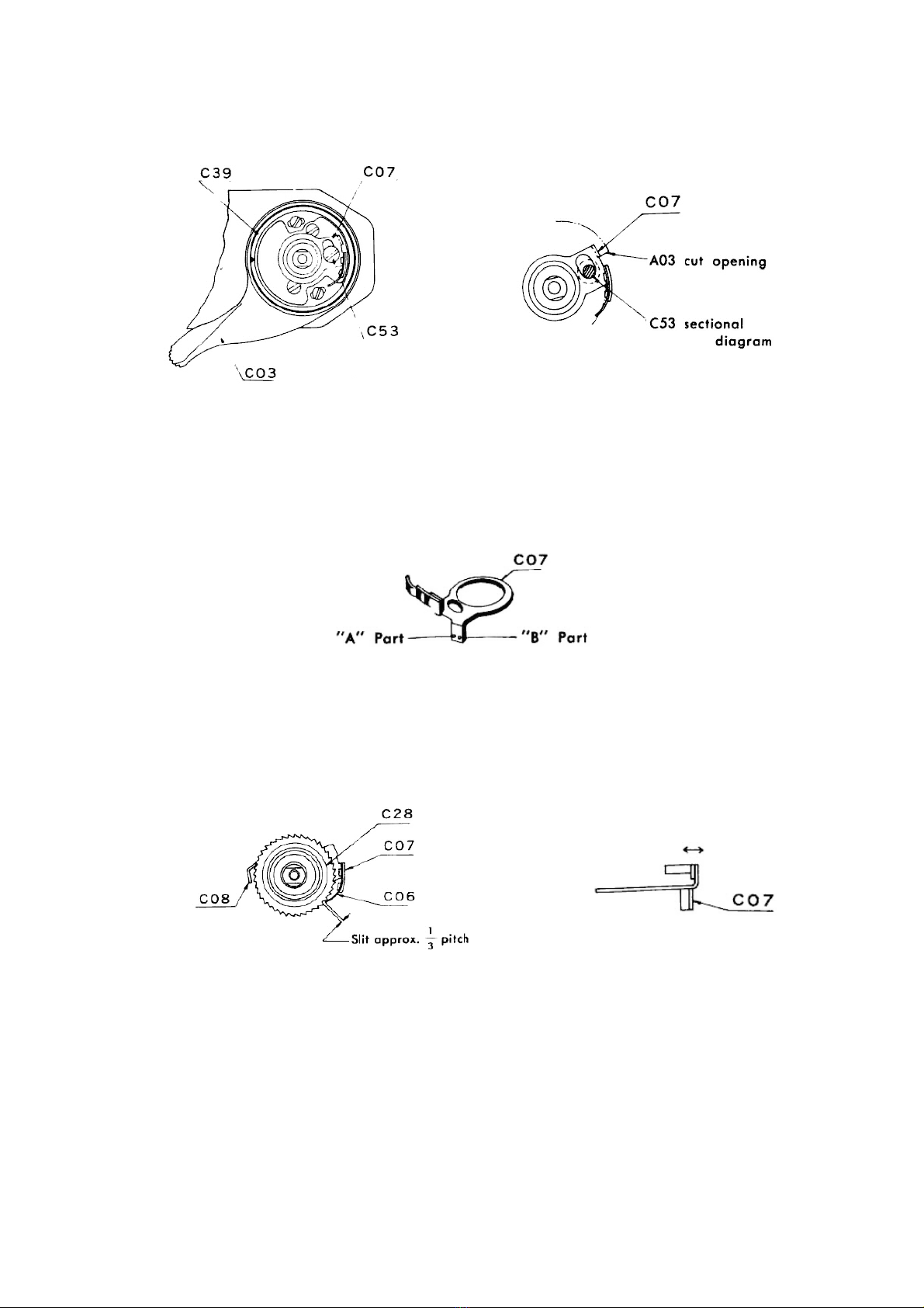
uncocked, (C07) should not idle inthe direction of its rotation, checked by the cut-opening of (A03), and
(C53). (Diagram 22, 23)
Diagram 22
Diagram 23
If the gap of (C07) is considerable, it will invariably result in the counter dial travelling double scale space
even by single cocking. In this event,itisnecessary tominimize the gap by hammering out the "A" part of
(C07). When (C53) can not be installed, file off !he "A" part. (Diagram 24)
Diagram 24
Then have onlythe transport gear (C28) ready,separated from (C12), installitand the counter retainer lug
(C08). Check the interlocking of the counter advance lug (C06) with the teeth of (C28), tosee that the gap
between the tip of (C06) and the teeth should be of approx. 1/3 pitch inthe direction of concentric circle,
with the rapid wind lever uncocked. (Diagram 25)
If the gap ismore than 1/3 pitch, (C07) must be bent inward, whereas ifthe gap isless than 1/3 pitch, (C07)
must be bent outward. (Diagram 26)
Diagram 26
Diagram 26
At this point, cock (C03) and let itreturn slowly. If (C06) travels smoothlyover the tips of the teeth of
(C28), the pressure of (C06) on (C28) may be considered proper. If (C06) comes toa stop at its tooth tip, it
is because the pressure is too strong, in which event it is necessary to bend and stretch out, however, with
utmost care not todeform or damage it.
NOTE: (C06) is annealed.
When (C03) iscocked, the transport gear (C28) must move by approx. 1 1/3 pitch by the counter
retainer lug (C08). (Diagram 27)
If moved less than 1 1/3 pitch,the "B" part (as illustrated in Diagram 24) must behammered out,
230-2 -20-
Table of contents
Other ASAHI Film Camera manuals


 Instructions for use")


