ASAHI AGRU SP 63-S Mobile V3 User manual


Version May 2021 EN 3
agru SP 63 mobile V 3 User’s Manual
Contents
1 Introduction ...........................................................................................................5
2 Safety Messages...................................................................................................5
2.1 The User's Manual ................................................................................................5
2.2 Explaining Icons ....................................................................................................5
2.3 Safety Messages and Information on Remaining Risk .........................................6
2.4 User/Operator Obligations ....................................................................................7
2.5 Worksite Description .............................................................................................7
2.6 Warranty................................................................................................................7
2.7 Transport and Storage ..........................................................................................8
2.8 Identifying the Machine .........................................................................................8
3 Product Description and Principles of Operation ..................................................8
3.1 Intended Use.........................................................................................................8
3.2 Machine Description..............................................................................................8
3.2.1 Component Overview............................................................................................9
3.2.2 Control Unit with Touch Screen.............................................................................9
3.2.3 Specications ......................................................................................................10
3.3 Welding Process Overview .................................................................................10
4 Operation ............................................................................................................11
4.1 Check-out, Turning on, Selecting the Display Language ....................................12
Zeroing the Position of the Movable Carriage.....................................................14
4.2 ConguringtheMachine .....................................................................................14
4.3 Changing Key Parameters of the Welding ..........................................................16
4.4 Entering Traceability Data for the Joint ...............................................................17
4.5 DenitionofWeldingParametersforAdditionalMaterials ..................................18
4.6 Fastening the Mechanical Structure of the Machine ...........................................19
4.7 Welding Process .................................................................................................20
4.7.1 Facing the Component Butts...............................................................................20
4.7.2 Checking Alignment ............................................................................................22
4.7.3 Inserting the Heating Element with or without Preheating ..................................22
4.7.4 Heating Stage .....................................................................................................22
4.7.5 Change-over Stage .............................................................................................23
4.7.6 Joining Stage ......................................................................................................23
4.7.7 Cooling Stage......................................................................................................23
4.7.8 End of Welding....................................................................................................23
4.8 Additional Preparatory Steps for Overhead Welding Operations........................24
4.9 Aborted Welding Process....................................................................................25
4.10 Indication of Joint Status and Possible Errors on the Tag...................................26
5 Printing Pipe Labels and Downloading Welding Reports....................................27
5.1 Downloading Welding Reports to a USB Stick....................................................27
5.2 Showing Reports in Memory, Printing Pipe Label Tags.......................................27
5.3 Using the Extended Report Viewer .....................................................................28
5.3.1 Viewing the Full Welding Report .........................................................................29
5.3.2 Ongoing Job Reporting Scheme and Statistical Overview..................................29
5.4 Deleting Reports from Memory ...........................................................................29
6 System Data........................................................................................................29
6.1 System and Maintenance Information.................................................................29
6.2 Enabling Automatic Heating ................................................................................29
6.3 Service and Repair..............................................................................................30
7 Service and Repair Contact ................................................................................31
7.1 Manufacturer Warranty........................................................................................31
7.2 Technical Documentation ....................................................................................31
7.3 Risk Assessment.................................................................................................31
Version May 2021
4 EN agru SP 63 mobile V 3 User’s Manual
Caution
The machine has to be operated exclusively with
a power supply line equipped with a protective
grounding conductor, as a power supply without
this safety element may cause severe machine
damage. If the machine is operated through a
power supply without a grounding conductor,
this will void any and all warranty under which
the product may be.

Version May 2021 EN 5
agru SP 63 mobile V 3 User’s Manual
1 Introduction
Dear Customer:
Thank you very much for purchasing our product. We are confident that
it will meet your expectations.
The development, manufacture, and check of the mobile, i. e., overhead-
welding-enabled, infrared butt-welding machine for thermoplastics has
been guided by our concern to offer a unit characterized by superior
operation safety and user-friendliness. The unit was manufactured and
checked according to the most recent standards as they are applied, and
bearing ergonomic aspects in mind.
To ensure maximum operation safety, please conform to the appropriate
messages in this booklet and the regulations for the prevention of acci-
dents. Carefully read the User’s Manual to avoid damage to the machine
or hardware in its environment as well as injury.
This manual is applicable to the following machines:
agru SP 63 mobile V 3
Thank you.
2 Safety Messages
This User’s Manual contains important instructions for operating the in-
frared welding machine for thermoplastics safely. Every person who oper-
ates the machine will have to conform to the instructions of this manual.
The machine has been developed and checked with respect to welding
agru pipes and fittings. For welding other makes, no experiential data are
available and/or no liability or warranty can be assumed for the fitness
and the reliable operation of the machine.
2.1 The User's Manual
The User’s Manual is presented according to sections which explain
the different functions of the machine. All rights, in particular the right to
copy or reproduce (in print or electronic form) and distribute as well as
to translate, are reserved and subject to prior written authorization.
2.2 Explaining Icons
The following expressions and icons are used in this User’s Manual to
refer to safety-related issues:
Caution
This icon indicates that non-compliance may result in a haz-
ardous situation that possibly causes bodily injury or material
damage.
Important
This icon indicates important messages related to the correct
use of the machine. Non-compliance may cause problems of
operation and damage to the machine.
Info
This icon indicates tips and useful information for using the
machine more efficiently and more economically.

Version May 2021
6 EN agru SP 63 mobile V 3 User’s Manual
2.3 Safety Messages and Information on Remaining Risk
Protect the power supply cord from cutting edges. Have an authorized
service shop replace damaged cables or lines immediately.
The machine has to be operated with a 230 V, 50/60 Hz power supply with
safety fuse or breaker of 16 A maximum. If power is connected through
a power line manifold, the power supply has to feature an earth-leakage
circuit breaker.
Use only extension cables with the following conductor sections:
– max. length of cable 25 m (80 ft) min. section 2.5 mm²
– max. length of cable 50 m (160 ft) min. section 4.0 mm²
Caution
Parts Under Power
After opening the machine or removing the cover, parts of it
are accessible that may be under power. The machine may be
opened exclusively by an authorized service shop and only
after it was disconnected from power.
Caution
Pipe Facing Tool
Start the pipe facing tool only when it is in its working position.
When facing pipes, do not wear jewellery; if needed, wear a
hair snood or net. It is forbidden to remove shaving from the
machine while the facing process is running. Make sure nobody
is present in this danger zone.
Caution
Heating Plate and Heating Plate Housing
When working with the machine, be extremely cautious while the
heating plate is operating. Since the plate and its housing guard
present a very high temperature during the welding process, it
must not be operated if unobserved, and sufficient distance to
combustible materials in its surroundings has to be ensured.
Do not touch the heating plate or the plate housing. The safety
alerts affixed to it have to be complied with strictly.
Caution
Danger of Bruises and Injury
Do not remain in the danger zone while the machine opens or
closes and be sure not to have your hands between the moving
and the fixed parts of the machine.
Caution
Acceptable Work Conditions
The work zone has to be clean and has to have proper lighting.
It is dangerous to operate in a humid environment or close to
flammable liquids. In regard of this, acceptable work condi-
tions have to be ensured (e.g., sufficient distance between the
machine and other functional areas of the workshop).
Overhead work is prohibited, unless:-
• themachineissafelyandsecurelyfastenedandpositioned;
• accesstoalargeareaaroundtheworksiteiscontrolled/limited
•(risk of falling objects); see also Sect. 2.5;
• ahardhatandsafetygogglesareworn(riskoffallingobjectsand
•small blades of shaving during component facing)
• properprotection(e.g.,byshieldingmembranesorfoils)against
•humidity, draughts or airflow if there is any risk that they should
•appear
Important
Power Supply Only through Line with Protective Grounding
Conductor
The machine has to be operated exclusively with a power supply
line equipped with a protective grounding conductor, as a power
supply without this safety element may cause severe machine

Version May 2021 EN 7
agru SP 63 mobile V 3 User’s Manual
damage. If the machine is operated through a power supply
without a grounding conductor, this will void any and all
warranty under which the product may be.
Important
Power Only to Operational Machine
Power must never be applied to the machine before it is com-
pletely installed and ready for operation.
Info
User’s Manual
The User’s Manual has to be available at any time on the site
where the machine is used. If the User’s Manual should come
to be incomplete or illegible replace it without delay. Feel free
to contact us for assistance.
2.4 User/Operator Obligations
• Themachinemaybeoperatedexclusivelybypersonswhoarefa-
miliar with the applicable rules, the guidelines for the prevention of
accidents, and the User’s Manual.
• Themachinemaybeoperatedonlywhenobserved.Onlypersons
who were properly trained by agru or another, authorized organi-
zation and whose training was acknowledged by the appropriate
certificates are allowed to operate and observe the machine. Other
persons must neither operate nor observe it.
• Theoperating/owningorganizationengagestocheckatreasonable
intervals if the machine is operated by the users with the intended
use and under proper guidelines of safe work.
• Themachinemustneverbeoperatedifnotinproperstateofrepair.
Before welding, the user is required to make sure that the state of
the machine is in order.
• Theuserhastomakesurethatonlyonepersonispresentinthe
zone where the machine is operating.
2.5 Worksite Description
• Theconditionshavetofullyensurethatthemachinecannotslide.
As well the segments of the base plate as the mechanical structure
and the base plate have to be securely connected to each other
before any components are clamped fast. In case of (overhead)
welding operations using the mechanical structure without the base
plate, the welding mechanics has to be securely fastened at the
components to be jointed with the supplied belts.
Important
For an overhead operation, the full weight of the mechanical
structure has to be carried by the belts. “Hanging” it from
the components to be jointed, so the clamps would carry its
weight, is prohibited.
• Worksiteaccesslimitationshavetobeprovided.Appropriateequip-
ment to achieve this can be requested from a service point or the
selling entity.
2.6 Warranty
Warranty claims may be raised only if the conditions for warranty given
in the General Terms and Conditions of Sale and Shipment obtain. One
precondition is that proper maintenance according to the required sched-
ule (see Sect. 6.3) is ensured.
Info
The term of warranty under which the welding machine is
shipped is 12 months:-
— from the date of purchase, if the machine is bought as a new
—machine;
Mobile Stumpfschweißmaschine
Typ agru SP 63 mobile V 3
Geräte-Nr. 06421123
Netz 230V 50Hz 1700W IP54
Gewicht ca. 49 kg Baujahr: 2021
Lizenzhersteller
HÜRNER Schweißtechnik GmbH
Nieder-Ohmener Str. 26
D - 32325 Mücke
Typ agru SP 63-mobile
Exklusives Produkt der Fa.
agru Kunststofftechnik GmbH
Ing.-Pesendorfer-Str. 31
A - 4540 Bad Hall
Tel. +43 7258 7900
Fax +43 7528 3863
Version May 2021
8 EN agru SP 63 mobile V 3 User’s Manual
— from the date of first use, if the machine is used independently
—of purchase (e.g. when lent) or if it is not bought as a new
—machine.
2.7 Transport and Storage
During transport, the machine must be at all times in the transport box
it is shipped in.
Important
Ensure that the heating plate, the facing tool, and all movable/
removable parts of the machine are safely stowed away and,
if applicable, secured with the transport lock during transport
at all times (see explanations and figures in Sect. 4.1).
The transport box should also be used to store the machine. The machine
has to be stored in a dry location, be clean or has to be cleaned, and be
locked against unwanted operation.
2.8 Identifying the Machine
Each machine is identified by a name plate. It shows the machine
model (“Typ”), its year of manufacture (“Baujahr”), the serial number
(“Geräte-Nr.”), the rated power (“Netz”), and the manufacturer (“Lizenz-
hersteller”).
3 Product Description and Principles of Operation
3.1 Intended Use
The agru SP 63 mobile V 3 Welding Machine is designed exclusively for
welding thermoplastic pipes and fittings using the butt-welding process
with plasticization by infrared beams.
Only the welding parameters shown on the screen display (prepro-
grammed by the manufacturer or defined by the user) can be selected
for a welding operation. If a modification of preinstalled parameters os
needed exeptionally, contact agru Kunststofftechnik.
It is also part of the intended use to conform to the instructions provided
in the User’s Manual.
Important
The manufacturer can in no circumstances be held liable for
damage or consequential damage that occurs as a result of the
non-compliance with the procedures described in the User’s
Manual, the modification of the manufacturer-programmed
welding parameters, or non-intended use. Any such deviation
or modification will void any and all warranties under which the
product may be.
3.2 Machine Description
The machine can be used as an in-shop installation, and with anodized
aluminum and stainless steel components, it is also suited for clean
room applications. The machine enables users to enter the data that are
relevant for the welding process and for the traceability of the welded
joint. From the entered welding parameters, it calculates automatically
the applicable forces, times, and temperatures and controls the semi-
automatic welding process.
All welding and traceability data are entered either directly at the machine
on its touch screen or read from a transponder card by the transponder
reader. The welding process in monitored in its entirety and saved to

Version May 2021 EN 9
agru SP 63 mobile V 3 User’s Manual
a welding report. All welding reports can the be downloaded to a USB
stick as an abstract, an extended report or as a DataWork database file.
Using the menus displayed on the touch screen, the machine can be
customized to the application in hand (see section 4.3).
3.2.1 Component Overview
3.2.2 Control Unit with Touch Screen
Heating Element and Guard
Housing
Facing Tool
Clamps
Dedicated Base Plate for Fac-
ing Tool and Heating Element
Fixed and Mobile Carriage of
Machine Frame
Locking Ball Pin to Secure
Base Plates to Each Other
RFID Transponder Reader
Control Unit with Control Touch Screen
Support Bracket für Facing
Tool and Heating Element
Thumb Screws for Locking
the Outer Clamp
(analogous on the other carriage)
Buzzer (at the front)
Heating Element Connector
(at the back)
Locking Ball Pin to Secure
Base Plates to Each Other
RFID Transponder Reader
Touch Screen Display

Version May 2021
10 EN agru SP 63 mobile V 3 User’s Manual
3.2.3 Specications
agru SP 63-mobile
Power Characteristics
Voltage
Frequency
Total Rated Power
Heating Element
Electrical Cordless Power Facing Tool
Charger for Power Facing Tool
230 V
50/60 Hz
1.7 kW
1.38 kW
18 V, 5.2Ah (on battery, w/ 2 batteries)
220 - 240 V AC, 50/60 Hz, 0.085 kW
Welding Operation Specs
Welding Force
Speed of Cordless Facing Tool
Ambient Temperature (operation)
Ambient Temperature (storage)
Operating Range
Travel Stroke of Movable Carriage
10 - 500 N
approx. 66 rpm (in 2nd gear, speed set to max.)
+ 10°C to + 40°C (50°F to 104°F)
– 5°C to + 50°C (23°F to 122°F)
20 - 63 mm (3/4" - 2-1/2")
approx. 115.5 mm (4-1/2")
Dimensions and Weight
Dimensions (W x D x H)
Mechanical Assy (carriage moved apart)
Electronic Assembly
Mechan. & Electron. on Base Plate
Dedic'ed Base Pl. w/ Facer/H. Elem.
Transport Case
Weight
Mechanical Assembly
Electronic Assembly
Mechan. & Electron. on Base Plate
Facing Tool
Heating Element
Dedic'ed Base Pl. w/ Facer/H. Elem.
Transport Case (w/ mach., access.)
Transport Case, emptyx
544 × 160 × 348 mm (21-7/16" × 6-5/16" × 13-21/32")
300 × 251 × 237 mm (11-7/8" × 9-7/8" × 9-11/32")
575 × 376 × 385 mm (22-5/8" × 14-25/32" × 15-5/32")
260 × 347 × 313 mm (10-1/4" × 13-21/32" × 12-11/32")
800 × 600 × 608 mm (31-1/2" × 23-5/8" × 23-15/16")
15.1 kg (33.2 U.S. lbs)
8.9 kg (19.6 U.S. lbs; on base plate)
33.2 kg (73 U.S. lbs)
4.6 kg (10.1 U.S. lbs)
3.9 kg (8.6 U.S. lbs)
15.3 kg (33.7 U.S. lbs)
89 kg (196 U.S. lbs)
30 kg (66 U.S. lbs)
3.3 Welding Process Overview
The welding process is performed as follows:
Important
Prior to welding, the mechanical structure of the machine has
to be secured, either to the base plate or to the components
to be jointed (see Sect. 4.6).
Connector for Power Cord to
Label Tag Printer
USB Interface
(to connect USB stick or tag printer)
Mains Socket & On/Off Switch
Emergency Stop Switch
Connector for Mechanical
Welding Chassis (control cable to
connector on back of control cabinet of
mechanics)
Status Bar (with product name, welder,
and current moment in time)
Screen Title Line
Touch Screen
Design Navigation Bar with
Control and Menu
Buttons
Area Showing Content Depend-
ing on Context (welding progress,
input keyboards, messages, etc.)

Version May 2021 EN 11
agru SP 63 mobile V 3 User’s Manual
• Thefacingtoolisinsertedbetweenthecarriages,intoitsposition
for clamping the components in the machine, and the clamps them-
selves are adjusted to the spacer pins of the facing tool.
• Thecomponentsareclampedandthefacingdistanceisadjusted.
• Thefacingtoolismovedtoitspositionforfacing.
• Pipeendsareworkedusingthepipefacingtooluntilacontinuous
blade of shaving material forms.
• Pipealignmentischeckedandconfirmedbythewelder.
• Insertionoftheheatingelement;wheninsertingit,theheatingele-
ment has to be clean.
• Aftertheheatingelementwasinserted,closinginthemovablecar-
riage is confirmed, and the pipes close in at the predefined force.
• Whenthecarriagesclosein,theyalsoaligntheheatingelement
exactly in-between the pipe butts.
• Thepipebuttsarethenheatedtothepredefinedtemperature.
• Whentheheatingphaseisover,thepipesaremovedapartauto-
matically to allow for manually removing the heating element.
• Oncetheheatingelementremovalisconfirmed,thepipesclosein
on each other again.
• Thisisfollowedbyasteadyforceincreaseuntilthefusionforceis
reached.
• Thepipethencoolsdownatthepredefinedforce.
• Afterthecoolingtimeisover,theforceisautomaticallyremoved
from the carriages and the pipe or fitting can be taken out of it.
4 Operation
Before putting the machine into operation, review the transport locks and
safety auxiliaries as well as the way the machine is set into its transport
box. Whenever the machine is moved or shipped, it has to be set into
this box and all locks and auxiliaries have to be engaged. The figures
below help with understanding the transport helpers.
Important
Whenever transported, the roll of labels in the printer has to
be removed and the batteries, placed into the cardboard box.
Mechanics and
Electronics on Base
Plate
Tabletop Plate with
Heating Element in it
Guard
Case with
Reducer
Inserts
Cardboard Box for
Facing Tool Batteries
Box for
Extension Cord,
User's Manual
and Other
Accessories
Facing Tool
Label Tag Printer
Charger for Fac-
ing Tool Battery
Version May 2021
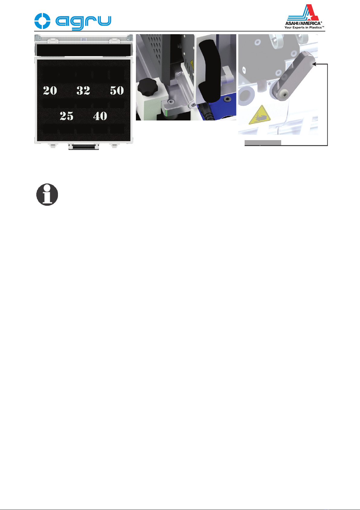
12 EN agru SP 63 mobile V 3 User’s Manual
Info
When installing the reducer inserts, place the narrower inserts
into the inner clamps, the broader inserts, into the outer clamps.
The insertion and the removal of the inserts is performed with-
out any tools. The reducers are secured to the clamps by the
force of the magnets only.
4.1 Check-out, Turning on, Selecting the Display Language
Place the machine on a level surface and ensure it cannot slide or secure
it safely at the components to be jointed. Sufficient distance has to be kept
to other areas in the workshop, especially to those in which combustible
materials are used, in order for the heating element temperature of up
to 500°C (930°F) not to be hazardous. When starting the machine up,
remove the transport locks before applying power to the machine if it was
transported before start-up and the locks were engaged. Furthermore,
if the label tag printer ist planned to be used later on, connect it to the
machine and insert the roll of labels before the first welding operation.
Independently of the order of the explanations in this booklet, the steps for
setting the machine up and preparing everything for welding are always
performed in the following order (see the following figures for reference):
1. Open the transport box.
2. Loosen the transport lock pole using the the star knob.
3. Take the dedicated plate for the facing tool and heating element out
of the box, set it on a level surface, making sure it will not slide, and
remove the transport lock of the heating element.
4. Take the base plate with the electronics and the mechanics out of
the box, set it on a level surface, making sure it will not slide, and
remove the transport lock of the movable carriages from in-between
the carriages (unlock the locking ball pin and remove it, then slide
the transport lock out of its seat in the opposite direction).
5. Take the facing tool out of the box and set it on its tabletop plate.
6. Take the battery charger out of the transport box.
7. Take the battery out of the carboard box, check the battery level
and charge the batteries as needed.
8. Connect the mechanics and the heating element to the electronic
control unit.
9. Connect the V-lock power cable to its socket and the mains.
10. Switch the machine on and zero the movable carriage position.
11. Insert the reducers into the clamps.
Inside view of the case for the
reducer inserts
Star knob (1 of 2) securing
the base and tabletop
plates, and transport lock
(self-locking pin, right
edge of drawing) of heating
element
Transport lock of carrier bracket
for facing tool and heating
element and of movable
carriage (locking ball pin as the
locking item on the other side of
the bar)
Version May 2021 EN 13
agru SP 63 mobile V 3 User’s Manual
Depending on the piece that is going to be welded, the outer clamps
may have to be repositioned or removed. To do so, loosen the locking
thumb screws and either remove the clamp or re-adjust it and secure it
by tightening the locking screws again.
If the diameter of the pieces to be welded is smaller than the clamp, insert
the reducer inserts. This can be done without using any tools since the
inserts are fastened in the clamps by magnetic attraction.
Important
Pipe clamps and reducer inserts have to be clean or must be
cleaned before welding starts. To insert or remove the inserts,
do not use heavy tools (hammer, wrench). They may damage
the inserts and the magnets.
Important
The surfaces of the heating plate have to be free of grease and
clean, or they have to be cleaned. Clean the heating element
only when it is cold. Refer to a service point for detailed infor-
mation on the procedures for cleaning the heating element.
Important
Make sure all connectors are tight in their sockets and make
sure that the machine is operated only if the conditions for safe
and intended use are met (see also section 2).
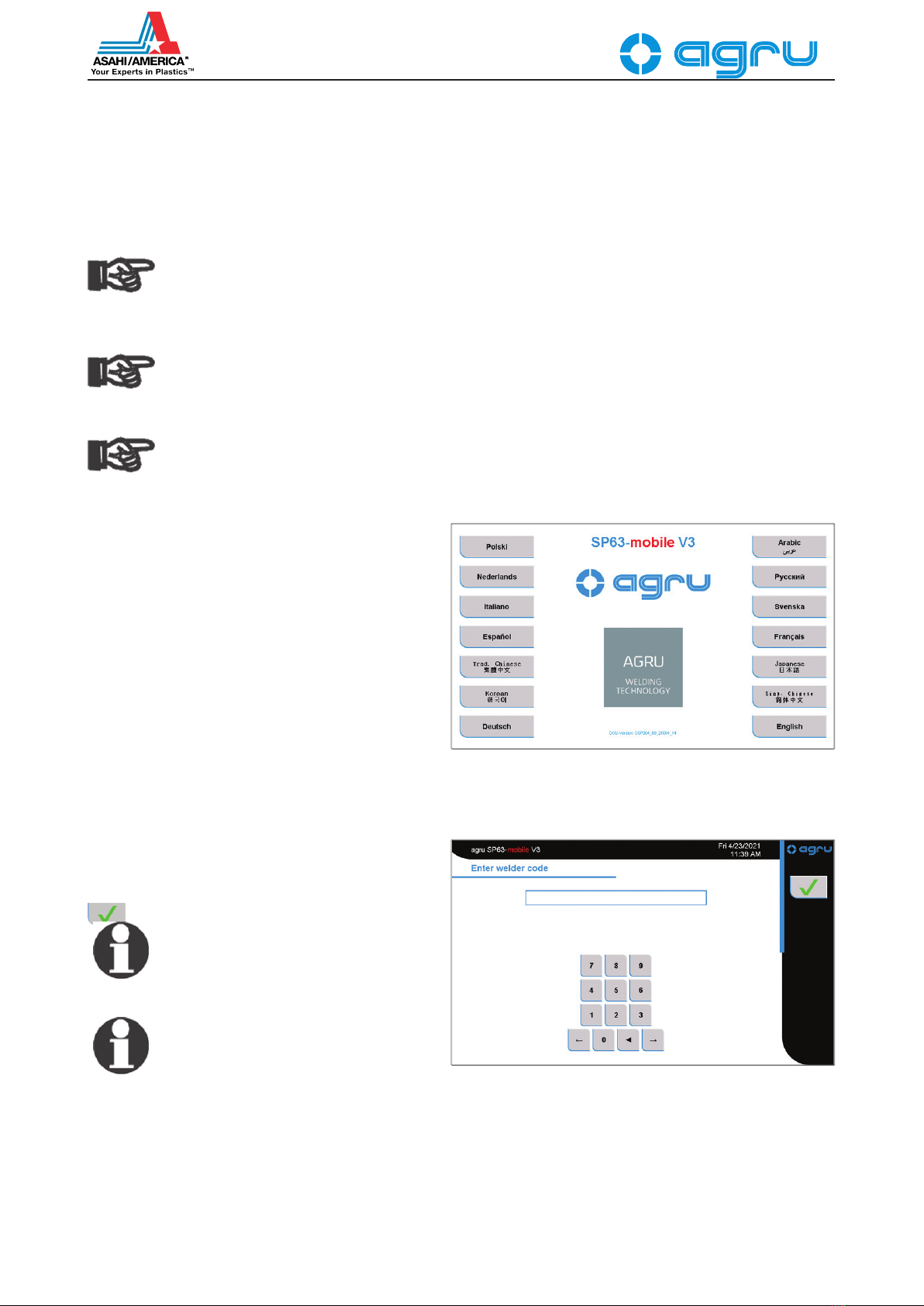
After preparing the machine for welding and con-
necting the power supply cord to the mains power
supply, the machine is turned on using the On/
Off switch. The welcome screen, as reproduced
in Display 1, appears on the touchscreen panel.
Touch the appropriate button to select the display
language that the machine will use. If needed,
the system clock will then have to be set, in
which case the relevant screen is displayed (see
Display 24).
After the language was selected, the machine
takes the user to the welder code input screen.
Without a valid welder identification code, the machine does not move
on to the preparation of welding and the welding process, since working
with the machine without a welder identification is prohibited.
Read the welder from a transponder card by
RFID. If no card with the welder identification
code is available, it can also be typed on the
keypad and saved to memory by touching the
button.
Info
All inputs for which a transponder card
is available can be entered by holding
the card in front of the RFID reader.
Info
Depending on the software version in-
stalled in your machine, some screens
may differ slightly on your machine from
the reproductions in this manual.
When the welder code was entered, the movement position of the movable
carriage has to zeroed (see below). Then the machine displays the so-
called default screen (see Display 3). In this display, it is possible to start
the welding process and to customize the configuration of the machine.
Display 1
Display 2

Version May 2021
14 EN agru SP 63 mobile V 3 User’s Manual
The welder will enter all settings and perform all control actions on the
touchscreen panel.
Zeroing the Position of the Movable Carriage
Important
Without zeroing the reference position of the movable carriage,
proper welding is impossible. Therefore, zeroing will be skipped
only when the machine remains at the same spot for the next
welding and no emergency stop was triggered. Zeroing the
carriage is required and cannot be skipped after the machine
was turned on or the emergency stop switch was pressed.
To zero the carriage position, the facing tool has to be removed from
in-between the carriages if it still is positioned between them — the
machine prompts on the screen to do so — , and the button must
then be pressed for confirmation. If the spacer pins of the facing tool are
placed in the recesses of the carriages and possibly refuse to slide out,
press the button. Then, the movable carriage can be moved apart
by pressing the carriage mover button (see the “Important” note at
the beginnig of Sect. 4.7).
The same holds for the heating element. If it is still set on the carrier be-
tween the two carriages of the machine, the user is requested to remove
it. Only after the removal was confirmed by pressing the button,
the process continues.
The same query appears again for the pipes/components that might still
be in the clamps from the last welding operation. They, too, have to be
taken out of them, which has to be confirmed by the button.
When the welder confirms that there are no pipes in the clamps, the
machine asks that the movable carriage be closed in on the fixed one
by holding down the carriage mover button , just as for facing, heat-
ing or joining, until the message “Zero point adjustment” appears on the
screen. When this message is showing, the machine determines the zero
point of the movable carriage as compared to the position of the fixed
carriage, that will apply for the next welding.
When this reference position/zero point was automatically zeroed and
saved to memory in the control unit, the machine asks the welder to
move the carriage apart, which indicated that the machine has now been
zeroed. To move the carriage apart, press the button. The machine
returns to the default screen (see Display 3). Welding can now be started
or parameters can be edited.
4.2 ConguringtheMachine
In the default screen (Display 3), the key param-
eters of the last welding are shown (material,
diameter, and wall thickness along with SDR
rating of the welded pipe). The following current
values show, now or only later, after the welding
was started, along the bottom edge of the screen:
heating element temperature, applied force, input
voltage and current, ambient temperature.
In Display 3, the welder has the possibility to:
• immediatelystartaweldingprocessusing
the same welding parameters as the previ-
ous welding (touch the button and move on to section 4.6);
• enter new component-related and traceability data and another
welder ID code for the next welding (touch the button and
move on to Section 4.3);
Display 3

Version May 2021 EN 15
agru SP 63 mobile V 3 User’s Manual
• changethemachinesettingsintheconfigu-
ration menu (touch the button);
• displayinformationontheweldingsystem
itself and its maintenance/service status
(touch the button and see Sect 6.2 for
reference);
• viewtheoperator’sguidelinesforthejoint-
ing of thermoplastic components (touch the
button; see Display 4 for reference).
Info
Other functionalities that are called
when the default screen is showing, are
explained below in this booklet, includ-
ing how to call them from this screen.
After the button was pressed, the part of the configuration menu
available to all shows. Use the arrow button at the bottom of the menu bar
at the right-hand edge of the screen to browse through the pages of the
configuration menu. The menu has the items listed in the following table.
In the menu, the button depicted at an option means that touching it
will open a submenu in which the configuration itself can be customized.
For functions that the user can enable or disable at their own discretion,
the (on) and (off) buttons indicate the current status. Touching
the button will toggle the function from one to the other state.
Any changes in the configuration menu are saved to memory and will
be used by the machine in the future when the respective configuration
option or the entire menu is quit by pressing the button.
Designation Setting Description / Data to be entered
Report View In a sub-menu, a welding operation can be selected in a list to
display the report recorded of that operation. From this screen, it is
also possible to print a label tag for this welding once again (see
section 5.2).
Select Number of
Labels
In a sub-menu, the number of´label tags (0 - 3) to be printed after
welding for purposes of identification, can be selected.
Select Unit of Length In a sub-menu, the unit of length used for displaying welding data
can be selected: millimeters or inches.
Select Temperature
Unit
In a sub-menu, the temperature unit used for displaying welding data
can be selected: centigrade or degrees Fahrenheit.
Buzzer if ON: The audible signal that validates certain steps in the process
is turned on;
if OFF: At the end of the respective steps no signal can be heard.
Set Volume of
Buzzer
In a sub-menu, the volume of the audible signal that the machine
emits to validate the execution of a given step in the process can be
set.
Automatic Heating In a sub-menu, a time, for instance on the following morning, can be
pre-set when the heating element will start heating up automatically
(see sub-section 6.2).
New Report View if ON: The Report View option of the menu calls an extended and
more powerful report view, which allows in-depth assessment and
analysis (this report view requires entering a Supervisor Code that
authorized persons, e. g. a project manager, can set and enter
themselves);
if OFF: The Report View option of the menu calls the standard, less
detailed report view of welding operations (this report view is also
displayed if the option is enabled, but the entered access code for
the new, extended report review is entered incorrectly).
Display 4

Version May 2021
16 EN agru SP 63 mobile V 3 User’s Manual
Bead Force while
Welding
if ON: During welding, the diagram depicted on the screen
represents the force exercised on the welding bead (i. e., for
instance, no force in the heating stage, as the applied force is not
exercised on the bead);
if OFF: The force depicted by the diagram in the course of the
welding process is the value exercised on the force transducer.
Select Language In a sub-menu, the display language of the machine can be selected
(see Display 1 for reference).
Automatic Mode if ON: steps of the process where the movable carriage of the
machine actually moves can be performed by starting its movement
using the carriage mover button in the lower left corner of the
screen; once started, the movable carriage will move to the left or to
the right for the proper duration computed by the machine for the
currently ongoing welding process step or available in the recorded
process data of a previous welding operation (see the “Important”
note at the beginnig of Sect. 4.7);
if OFF: steps of the process where the movable carriage moves re-
quire the carriage mover button to be used as an on-demand switch,
i. e., to be maintained in the pressed state for the full duration for
which the carriage is meant to move to the left or to the right. In this
event, it is under the welder's responsibility to monitor the duration
of the movement and the position of the moving carriage.
While the configuration menu is being displayed, two more buttons can be
seen in the navigation bar at the right-hand edge of the screen. The
button gives access to the system settings of the welding machine. They
are meant for specialized staff supposed to set up, service or, if failed,
repair the machine; therefore, they are not described in this booklet.
Just as the system settings, the extended operation settings of the
welding system, which can be accessed by touching the button,
are protected by a second access code, which will be disclosed only to
supervising staff with the operator. The parameters below can be custom-
ized in the extended set of settings after entering that code.
Designation Setting Description / Data to be entered
Memory Control if ON: The machine refuses further welding operations when the
memory is full;
if OFF: The machine overwrites the oldest report when the memory
is full.
Set Date/Time In a sub-menu, date and time can be set, provided no service of the
machine is currently due.
Delete Reports In a sub-menu, it is possible to delete all welding reports currently in
memory; the reports will be deleted only after another tweo safety
warnings were confirmed.
Enter Additional
Parameters
In a sub-menu, the characteristic welding parameters can be defined
for product/materials that are not available in the control software.
Enter Inventory
Number
In a sub-menu, the identifier can be entered by which the machine
has been entered in the inventory of its operator.
4.3 Changing Key Parameters of the Welding
In the default screen (see Display 3), it is possible
to change the specific parameters for the joint to
be welded. To do so, press the button. The
screen that allows selecting the material of the
components that are going to be welded, is then
displayed on the screen (see Display 5).
Info
The first selection screen may comprise
not only component materials, such as
PVDF or PP, but also so-called prod-Display 5
Version May 2021 EN 17
agru SP 63 mobile V 3 User’s Manual
ucts. A product is a parameter set of technical welding param-
eters either in memory ex works or defined by the user (see
Sect. 4.5 for reference); one of the parameters of the set is the
material of the component. In user-defined parameter sets, the
product name is at the user’s discretion. If one product has sev-
eral thermoplastic materials for which welding parameters exist
in memomry, after selecting that product the user is prompted
to select the material used in the upcoming welding operation.
If there is only one material for it, the machine moves on to
the diameter selection screen, just as after the selection of a
material rather than a product on the first selection screen.
To select a product or a component material, touch the appropriate button
on the screen. Analogous screens will follow that allow selecting, for the
component that is going to be welded, its diameter, its wall thickness,
and its SDR value. After every selection made, the machine switches to
the next selection screen.
Standard products/materials can be selected on those screens. Further-
more, the machine enables the jointing of additional products/mateirals,
i. e., additional parameter sets of characteristic welding data which are
either defined as additional parameter sets ex works before the machine
ships or set up by the user themselves (see Sect. 4.5).
Additional parameter sets are under an access code that has to be en-
tered and confirmed by touching the button, as soon as they are
accessed using the additional-parameter button . To whom this code
is disclosed is at the machine operator’s discretion.
The Product/Material or Material selection screens will always be show,
even if there is only one material or product in memory. All other selec-
tion screen appear only when a selection is actually possible. If, e. g.,
there is only one diameter in memory for a given material, no diameter
selection screen will be displayed.
Important
The machine must never be used to weld pipe materials, diam-
eters, and thicknesses other than those available in the welding
parameter screens. The manufacturer is in no circumstances
liable for damage or consequential damage that occurs as a
result of deviations from these pipe data or of modifications or
attempted modifications to the control software. Furthermore,
this will cancel any claims to warranty expressed for the ma-
chine. To make a material available in this screen, it has to be
entered previously with all its technical welding parameters in
the configuration menu.
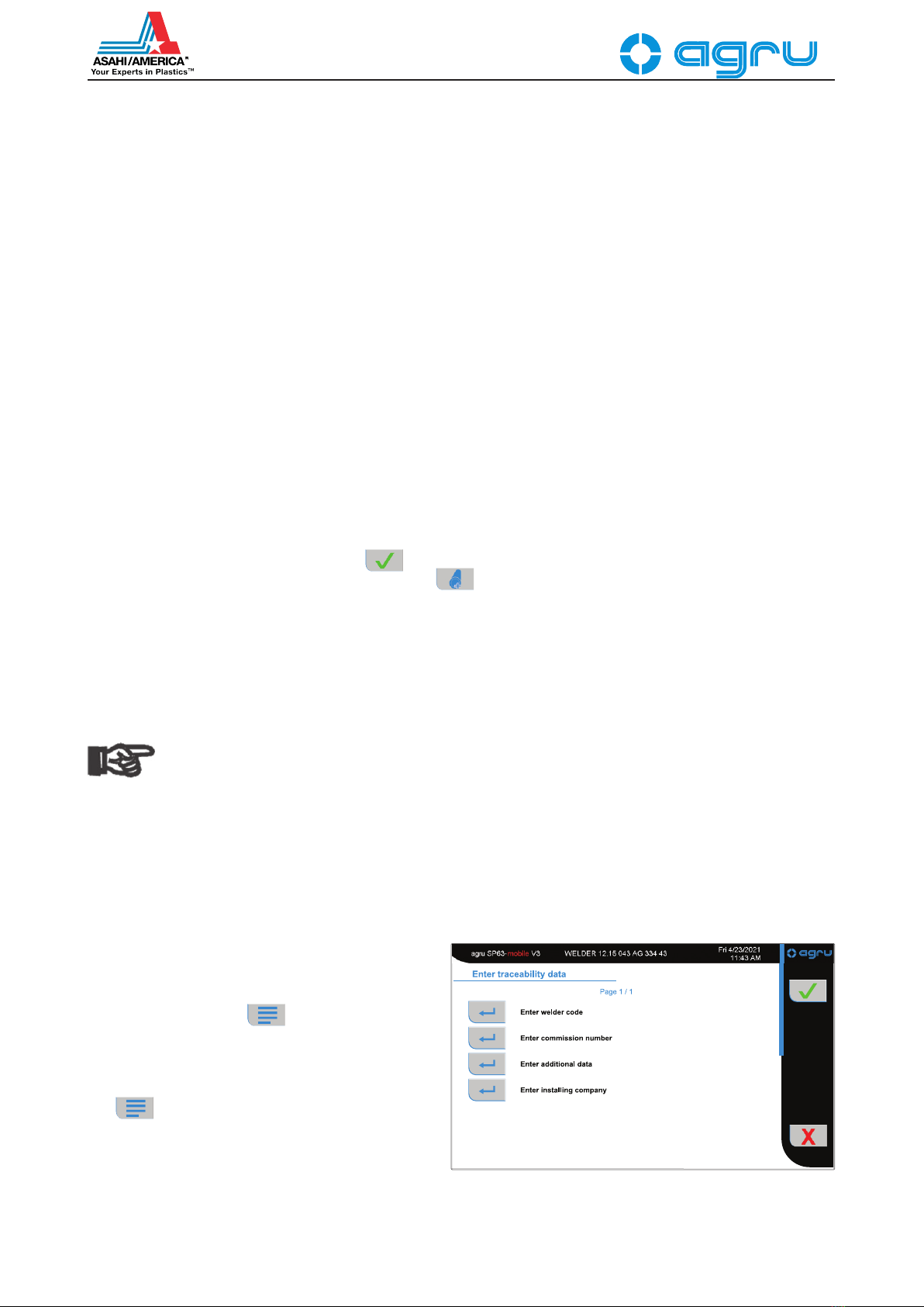
4.4 Entering Traceability Data for the Joint
On the screens that allow changing the techni-
cal parameters for the upcoming welding opera-
tion, by touching the button, it is possible
to access the traceability data for the joint and
change them as needed (see Display 6).
Independently of accessing them by touching
the key, the welder identification code has
to entered after switching the machine on (see
Sect. 4.1 and Display 2), as no welding operation
is allowed without a valid welder code.
The machine displays a menu that allows selecting the traceability
information to be changed (see Display 6). You can confirm all cur-
Display 6

ATH-7701-238-RT-990129
Version May 2021
18 EN agru SP 63 mobile V 3 User’s Manual
rent data — those from the previous welding — by simply touching
the button.
Change any data that require modification by touching the key at
the appropriate menu option. Depending on the kind of data you want to
change, the machine displays either a numeric keypad (see Display 2)
or an alphanumeric keyboard (see Display 7). To confirm and save your
data input to memory on the data input screen, touch the button.
4.5 DenitionofWeldingParametersforAdditionalMaterials
The extended set of settings in configuration
menu (see section 4.2) has an option “Enter Addi-
tional Parameters” for defining the technical data
the machine should use when welding materials
not currently available in system memory.
If no additional, operator-defined welding param-
eter set has been saved to system memory, the
screen for the product name appears, to start
the input of a full parameter set (see below). If
there are, the parameter set overview shows and
presents them line by line (see Display 8).
The button to the left of an entry in the additional welding param-
eter overview opens the menu for managing
the additional parameter sets. It offers re-entering
all parameters of the set just selected, editing its
individual parameters, deleting it, and deleting all
additional parameter sets. Again, select the de-
sired option by touching the button next to it.
Instead of the menu, a screen that allows enter-
ing the product name to be saved to the new
parameter set is shown if the button next to
a blank line was touched. After this, in a series of
individual screens enter all welding parameters
that the parameter set should hold and set on/off
values such as whether or not the components have to be aligned before
facing, to the desire state using the toggle switch. Confirm
every value by touching the button, to move on to the next screen.
Starting from the management menu, the re-enter parameter set option
has the same effect, except the individual input screens are not blank.
They will hold the values currently set for the parameter set that was
previously selected in the overview, by touching the button next
to it to open the management menu.
Selecting the edit parameter set option in the management menu will show
a table-style overview of the previously selected
parameter set (see Display 9). The individual
parameters shown here depend on which on/off
values are set to on in that parameter set. The
menu-like overview of the on/off values of the
set, in which they can be enabled and disabled,
is accessible by the button. The individual
parameter values can be edited after touching
the value itseld in the overview table, thereby
opening an input screen for that value. When
editing parameter sets, too, every change has
to be confirmed by the button.
Display 7
Enter Commission Number
Display 9
Display 7
Display 8
Version May 2021 EN 19
agru SP 63 mobile V 3 User’s Manual
Both kinds of deletion in the additional parameter management
menu — deletion of the welding parameter set previously selected in the
overview list and deletion of all additional welding parameters — require
the subsequent confirmation of two warning messages.
Info
If the product/material that was used in the last welding opera-
tion is deleted, the product/material selection screen (refer to
Sect. 4.3) opens automatically upon closing the parameter set
management, then the configuration menu, and a new product/
material has to be selected.
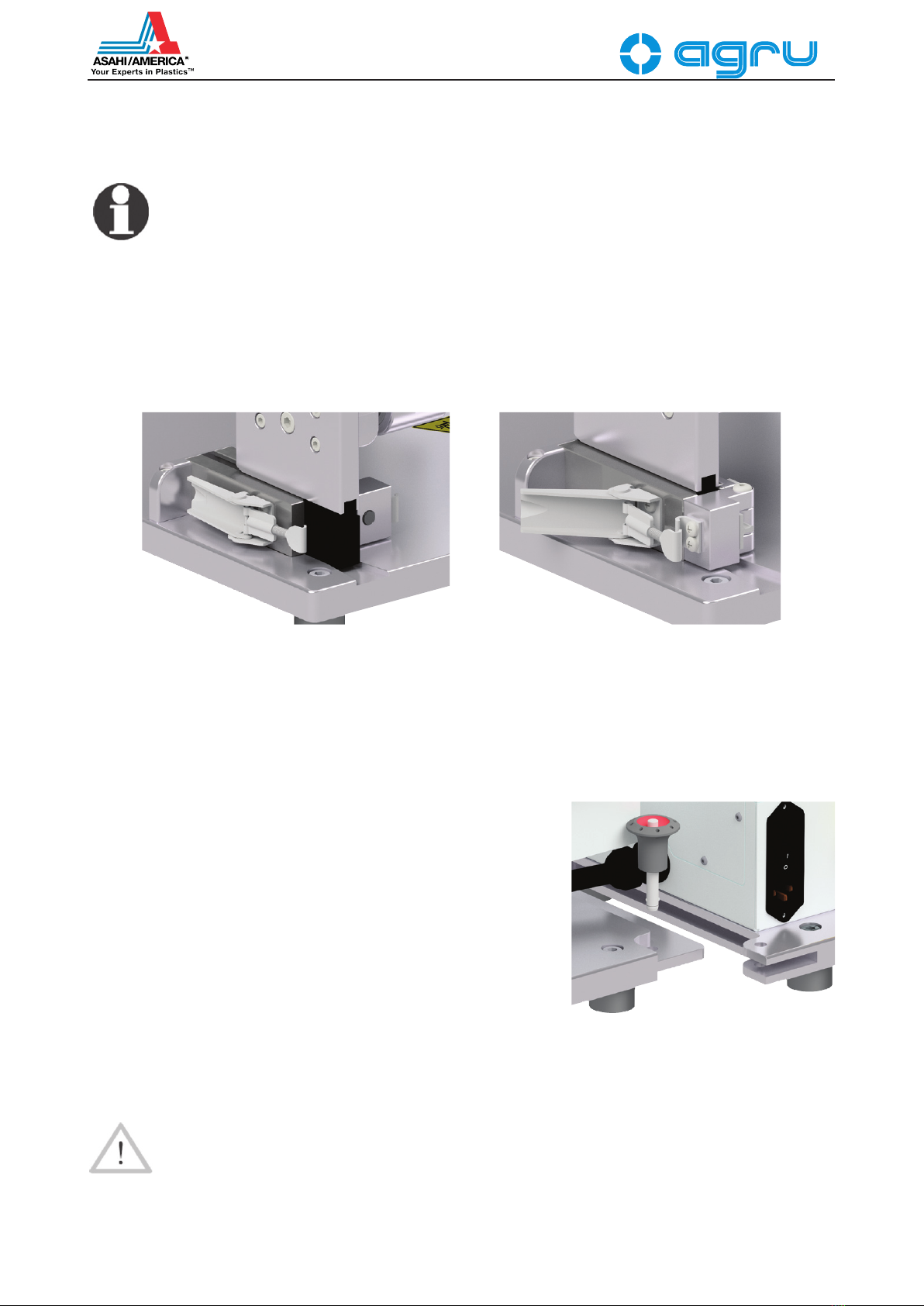
4.6 Fastening the Mechanical Structure of the Machine
The mechanical structure (chassis) of the machine is fastened to or
unfastened from the base plate using the lock frames that the black
anodized-aluminum legs of the structure plug into (see left-hand drawing
for reference). The leg is secured inside the frame by the fastening latch
at its back (seen only in the right-hand drawing), which, in turn, is kept
in place by the lock flap hooked into the fastening latch and then tilted
towards the back, along the leg. The traction excercised on the fasten-
ing latch by the flap can be adjusted by shortening or lengthening the
threaded pin that hooks into its mate at the edge of the latch.
The grooves in the base plate help slide the legs of the mechanical
structure into the lock frames into which the plug.
Prior to fastening or unfastening the mechanical structure, discon-
nect all electrical and control cables; reconnect only when
done.
A second step of fastening the mechanical structure to the base
plate, when it is not planned to use it separate from the plate, is to
lock the plates to each other by sliding the one into the other and
securing it using the locking ball pins at the front right and back
left corner of the plate of the electronic control unit (see drawing
to the right, which only shows the locking ball pin at the rear). To
unlock a locked pin, push down the head of the pin inside the head.
To conclude the preparations of the welding process, connect
the two control cables: the one shown on the drawing to the right to the
connector at the back of the mechanical structure and the one from the
heating element to that on the right-hand side — when looking at the
keypad — of the electronic control (see Sect. 3.2.2).
Caution
When the mechanical structure is properly fastened to the base
plate, the fastening elements ensure a safe welding operation.
If the machine is used without the base plate, make sure that it
is positioned safely — including sufficiently far away from flam-
mable and combustible substances — at the components to be
jointed and that any needed means and auxiliaries of support
are indeed used.

Version May 2021
20 EN agru SP 63 mobile V 3 User’s Manual
Display 10
Caution
When they are not being used and held by the support between
the carriages of the machine, the facing tool and the heating
element have to be inserted by their bars meant to hold them,
into the respective opening of the tabletop support (see draw-
ing to the right).
4.7 Welding Process
With or without calibrating/zeroing the carriage position (see at the end
of Sect. 4.1), the machine returns to the default screen (see Display 3).
If technical welding parameters or traceability data have to be changed
or entered and this has not been done before, it is still possible at this
point after pressing the button (see Sect. 4.3 and 4.4). If it is not
needed, the welding process, with the current welding parameters and
traceability data, is started by pressing the button.
Info
Possibly the welder has to wait for the heating element to
reach the nominal temperature. This would then be indicated
on the screen. If the temperature difference between actual and
nominal is large, an additional delay may occur during which
the final temperature is adjusted.
When the welding process was started, the screen first shows a message
telling that the automatic mode is either on or off, that is, moving the
movable carriage either requires the carriage mover button in the lower
left corner of the screen just to be pressed once to start them and then
they are performed automatically, or require the button to be pressed all
the time for the movement to be performed for its full duration (refer to
the explanation of the automatic mode in the table in Sect. 4.2).
Important
The carriage mover button in the lower left corner of the screen
(see Displays 10, 11) that has to be held down to perform an
action involving movement of the carriage — automatic mode
off — or to be touched to start that movement — automatic
mode on — may be represented in three different ways:
= The next action involving movement will be to close the
carriage in on the other one, towards the point of jointing.
= The next action involving movement will be to move the
carriage apart, away from the point of jointing.
= At this point, the welder has to confirm a step of the pro-
cess and, as a consequence, the movable carriage will move
automatically (with automatic mode both on and off) for a short
distance or not at all (with automatic mode off, rather than the
round carriage mover button with a check mark in the lower
left corner, the key-shaped OK/confirmation button in the
upper right corner of the screen will be used for this kind of
confirmation).
4.7.1 Facing the Component Butts
The welding process starts by the insertion of
the facing tool, then the clamping of the com-
ponents (see Display 10). For the machine to
switch a next step, the preceding step has to be
confirmed using the carriage mover button (see
the “Impotant” note at the beginnig of Sect. 4.7).
Important
Make sure that the plate carrying the
facing tool and the heating element is
set on a surface where it can sit safely
and does not slide throughout the entire
welding process.
Version May 2021 EN 21
agru SP 63 mobile V 3 User’s Manual
First, the machine asks the operator to insert the facing tool into posi-
tion 1. This is the position for clamping the components. In this position
the spacer pins of the facing tool do not sit in the recesses of the clamp
bodies in which they are during facing. Slide the facing tool in-between
the carriages of the machine in position 1 and confirm it is in place by
pressing the carriage mover button (see the “Important” note at the
beginnig of Sect. 4.7).
When the facing tool is located between the components, with automatic
mode enabled, the machine closes the movable carriage in on the facing
tool. Without automatic mode, hold down the carriage mover button
(see the “Impotant” note at the beginnig of Sect. 4.7)
When the mobile carriage has been moved in on the fixed one, clamp
the components to be jointed into the clamps. While the screen that
requests this of the welder can be seen, it is
possible, using the Minus and the Plus buttons,
to decrease or increase the distance the carriage
will travel during facing (see Display 10). When
the facing distance is as desired, confirm by
pressing the carriage mover button , and the
machine moves the carriage apart for the next
process item, or, with automatic mode disabled,
hold down the carriage mover button (see
the “Important” note at the beginnig of Sect. 4.7).
The next process item is to move the facing tool
from position 1 to position 2, the position for
facing proper. Again, the screen requests this of the welder. To move
the facing tool, release its position lock. When it sits in position 2, press
the carriage mover button (see the “Important” note at the beginnig
of Sect. 4.7).
Info
Prior to the facing process, checking the direction and the speed
of the rotation of the power facer is recommended.
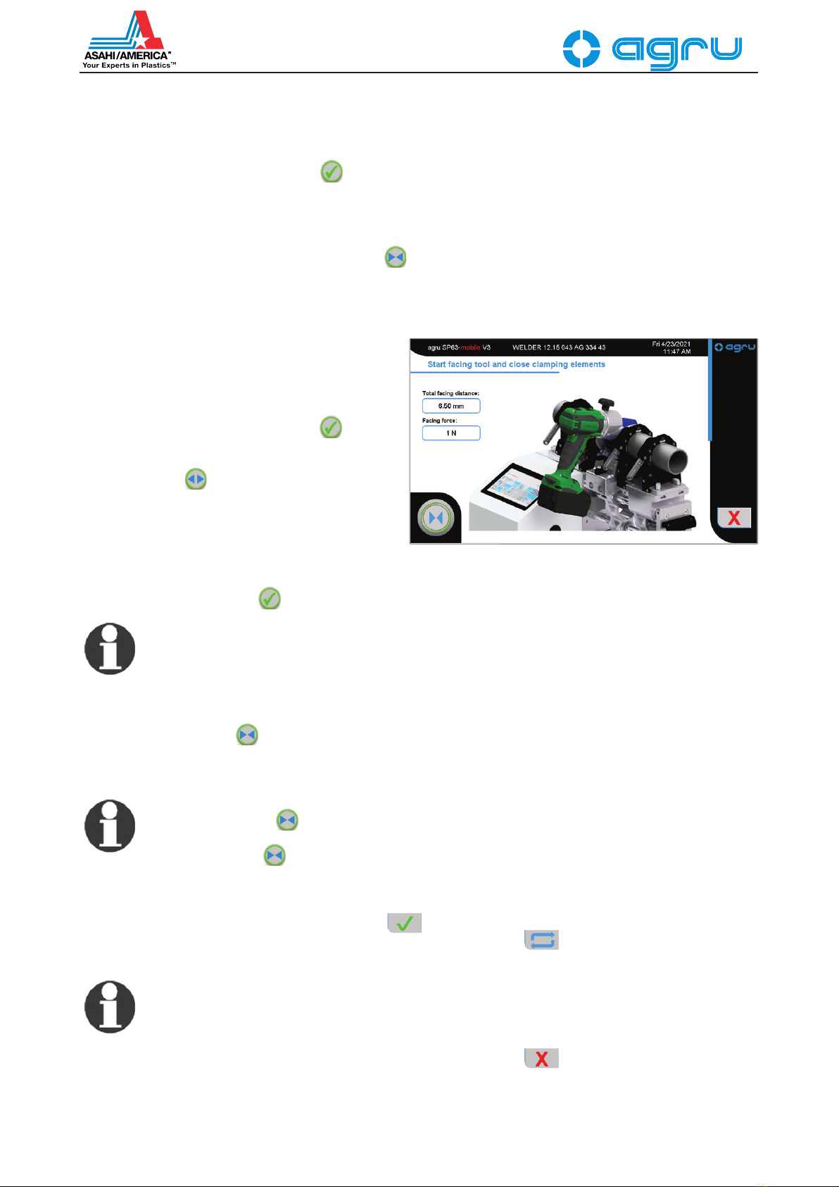
The machine then asks the welder to start the facing tool. Do as you are
requested, using the On/Off switch of the power facer, and hold down the
carriage mover button until the machine moves the carriage apart
automatically (see Display 11). This indicates that the facing process is
correct, considering the previously set facing distance. Then switch the
facing tool off at its On/Off switch.
Info
If the mover button is released before the carriage moves
apart, the facing tool pauses to allow for removing shavings;
holding down the button again to resume facing.
When the machine has moved the carriage apart, the facing tool can be
removed from in-between the pipes. Visually check the components and,
if they are o.k., confirm this by pressing the button. If the result
of facing is poor, the process can be repeated after pressing the
button. To face the ends once again, in most cases the pipes have to be
re-adjusted in the clamps.
Info
If an error occurs during facing, the machine moves the mobile
carriage apart, displaying the corresponding error message.
The facing process can be aborted at any time by pressing the
button.
Display 11
Table of contents
Popular Welding System manuals by other brands

FRONIUS
FRONIUS FDV 80 operating instructions

Elettro C.F.
Elettro C.F. TIG 4080 instruction manual

FRONIUS
FRONIUS TPS/i Robotics TWIN Push operating instructions

Uni-Mig
Uni-Mig RAZOR CUT 45 PFC operating manual

Alfain
Alfain PEGAS 161 E softswitch operating manual

Truweld
Truweld ARWSC900 Operation manual


